If you try to use a TLS network connection on an ESP8266, you'll find you rapidly run out of RAM and flash--at least, if you program it using the Arduino tools. Crypto like that is pretty big, especially if you're using a properly sized set of TLS certs. (My foray into this world was primarily with the Azure IoT Hub SDK.)
So, I'm doing what I did on my AirQualSniff project: Unencrypted and insecurely authenticated MQTT over my LAN. It's not ideal, but it'll work for now and means I don't have to worry about code size or cert rotation.
I really like Particle.io's solution, but it's tied to their hardware and has pretty severe payload size limitations. While not an issue for a Geiger counter, it hurt when working on AirQualSniff.
Now that all the circuit boards are mounted in my enclosure and are wired up...well, it won't close. The wires are too bulky. I'm thinking for future projects like this, the "haphazard wiring" solution will trigger a sort of rule-of-thirds: Leave about a third of the volume for wiring.
This isn't the first time I've hit this problem; my Eve pendant project should(TM) fit in the tiny pendant the way I designed it, but only if wiring is infinitesimally thin. That project will require some serious iteration; this one can probably get away with a 3-D printed spacer shell until I have the chutzpah to work on the next iteration.
My friend, [Ramjet], has a workshop with many tools for the shaping of matter and he knows how to use them. He is also leaving my area soon to make a COVID-safe months-long visit to family, rendering that expertise out of reach. Fortunately, he agreed to spend an entire Saturday helping me get my collection of loose circuit boards mounted in the project enclosure.
Twelve hours of masked work (less a short break or two) paid off!
(Pictures and details after the break)
---------- more ----------
Here's the front panel with it on:
Here you can see the completed front panel of the Geiger counter, complete with TFT display, OLED display, four buttons, four LEDs, buzzer, IR receiver, and potentiometer. While I'm quite happy with how it turned out, this picture lets you see some of the imperfections, like the imprecise hole placement and sizing for the lower right section, the visible Dremel learning curve in the TFT and OLED screen apertures, and the screen insets due to a lack of ideal mounting hardware.
Registration
Hole registration--getting all the holes in the case aligned with the holes in and features on the parts--was probably the single hardest part of the entire project. This is where [Ramjet]'s skills came into play; he has a simple trick where you put toothpaste on the part where it will be in contact with the surface, touch the surface with the part, and then drill holes in the surface where the toothpaste lands. He usually uses it to mark where on a wall he needs to put mollies, but it also worked well at this scale. I'm especially proud of the fit of the switches and alignment of the IR receiver.
This process worked iteratively, too. For the three buttons, there were two sets of holes: one for the buttons and one for the (M2) bolts. We toothpasted the buttons, marked the surface, drilled the holes, checked their alignment (no reaming needed on this one, as I recall!), then--because the standoffs on the button PCB could now reach the surface--we rinsed and repeated the process for them.
While it reduces catastrophic hole misplacement, it is not quite precise enough to avoid small misalignments easily solved by reaming. It also does not work on parts that don't play nice with toothpaste, like the screens, LED-button combo, and buzzer. (Well, we toothpasted the rim of the buzzer to align it.) For the LED-button combo, we used the more imprecise 'trace with pencil' method and a too-large bit to punch the hole. This is why you can see the PCB through the hole. (The left red LED hole was originally drilled for the potentiometer knob, so it needed to be reamed out pretty heavily.)
Getting the screen openings right posed a challenge, as you can tell from the larger one. There were three issues: marking the correct dimensions on the surface, kerf placement (also known as "oops, I cut too far"), and getting the Dremel tool to do its user's bidding. The smaller opening was done second with the last millimeter or so done with a file and frequent fit checks, so it came out much cleaner.
Mounting
Here's the back of the front plate:
Here you can see the various bits connected to the front panel: the button board, switch+IR board (mounted perpendicular using epoxy and wood blocks), TFT board, OLED board, and power+misc board. This is after I hooked it up and got it working again, so there are wires flying all over the place.
When [Ramjet] saw my awkward switch mounting situation (described in a previous log), he reached for some spare mix-and-set epoxy he had sitting around and devised the wooden block+epoxy situation you see here. It means I can't recover the parts on that board without considerable probably-destructive effort, but it also means they're solidly mounted.
Here are two shots of the main enclosure from different angles:
This shot shows the BMS, I2C splitter board, ESP8266-based GK-WiFi board, and GK Plus main board. Note the wire+screw BNC connector on the right, where the wire fills in as the mounting nut. Oh, and the rat's next of wires continues.More of the rat's nest from the previous picture, with more of the GK Plus board visible. Note the BNC connector visible on the right edge of the photo. Please pardon the cat toy in the background. =^.^=
Drill Template
Placing and drilling the holes in the main enclosure ran into some problems. Version 1 highlighted for me the need to more accurately place the holes, but the layout I had developed on the foam board wasn't accurate enough to catch that the I2C buss board and the GK-Plus-GK-WiFi combo would collide. (It missed the box's taper and the size of the frontplate attachment holes.) The latter is why those boards are mounted at an angle. For the former, [Ramjet] came up with the idea of first doing the toothpaste-drill-ream process on a rigid template, then using that to guide drilling in the actual case. This felt like it was going to double the work, and it kind of did--finding and fitting the template to the bottom of the enclosure was a lot more work than I expected, but for most of the holes the second round of drilling was really fast. (A few of the holes wee too close to the edge for even the Dremel tool to get to them, so we ended up hammering a finishing nail through the hole in the template to make a dimple on the outside that could be drilled into the waiting, guiding hole in the template inside.)
This here is the piece of acrylic that was hewn into shape to fit snugly at the bottom of the enclosure, then was drilled and reamed to eventually fit the various parts. The arrow made it so that each time we pulled it out and filed it or chiseled it, we put it back in in the same orientation. It also helped make sure all the holes ended up on the same side with the same orientation. The hole with an X drawn through it was a bad one, showcasing one of the benefits of this template approach. You can see the skiddywompus placement of the left five holes required to keep the GK WiFi and I2C interconnect boards from attempting to occupy the same space--something that classical physics frowns upon.
Mostly Done
It is really, really nice to have everything mounted. The foam board made it hard to mount and dismount the boards and didn't have anywhere to put the extra bits as I built them. Every time I unplugged a wire, I had to worry about pulling the hole board out instead.
Thanks again to [Ramjet] for all the help!
Next Steps
There are two remaining issues: the TFT (larger) screen's cabling is sensitive to noise and needs shielding, and the BNC connector needs to actually connect to the high voltage output of the GK Plus. On top of that, the ESP8266 firmware is low on RAM and lacks some features I want. Oh, and the rat's next doesn't fit in the box yet; I may yet have to get even more creative to get past that.
(Yes, a lot of this would probably have been simpler with a 3D printer or a laser cutter. Due to COVID-19 safety measures, I currently have access to neither.)
With the electronics successfully mounted to the foam board and a good chunk of the programming done, Version 1 is done.
It is now time to face my nemesis, the enclosure, for Version 2.
Some time ago, once I had the larger components figured out, I acquired a Hammond Manufacturing 1591XXESBK project box for this. (This is what provided the outline and size constraints in the v1 mounting post's pictures.) I also found a shiny power button, some nice tactile buttons, and a couple of switches to go with it. A few protoboards, some solid wire, the upcoming long absence of a friend with hand tools know-how, and the motivation of participating in the Hackaday Remoticon got me over the line to start prepping the project to get bolted into a proper home.
---------- more ----------
I ruminated a bit about how to fasten circuit boards and screens to the front plate and ended up at "If I can roughly lay out the front-plate elements, I can group them by component height and build up the boards. Once they're securely on boards, my friend can help me figure out mounting."
This started with a sketch in OneNote, where I added notes and boxes as I picked where to put what:
This sketch lays out where the major components will sit in the bottom of the case, where the major connections are, where the user-facing elements will sit, what kinds of boards they'll be on, and some other design choices like LED current-limiting resistor selections. I ran out of time, so the LED board connections are not yet charted out.
Button Board
The first board was pretty straightforward: a 100-mil header and three buttons:
Here we see the three tactile switches with their keycaps and some soldering connections visible.Note how I ran the ground connections all along one edge and the digital I/O connections along the other, all terminating at a side-facing 100-mil header.. This board was simple enough that everything is relatively pretty.
The only real challenges here were working with the header-end of the wires to make sure nothing shorted. I double-checked the button pin assignments several times, then did a round-robin continuity check after I was done to make sure everything was working.
Switch Board
The second board was more challenging. I misread the mechanical drawings of the toggle and on/off/on switches I bought, so the pin spacing was wrong. On top of that, the 250Vx2A-rated leads were too thick to fit through the holes on my board. By happy happenstance I noticed that some wire terminals I had incidentally acquired (in a bundle with the perf board) were 100-mil spaced and the switch pins fit into the screw-down terminals. I'm not sure how I'll attach the resulting combination to the front plate, but it works and provides a nice place to mount the IR receiver:
Here we see the switches in their screw-terminal receivers along with their respective 100-mil headers (that are, yes, askew). The IR receiver is in between the switches facing towards the surface the switches will project from. I ended up soldering the IR bit last, and it was a bit of a pain having to dance around the two big blocks of plastic next to it. Fun fact: the IR bit was placed here after I thought I had finished the board and realized it didn't really fit anywhere on the LED board (described later). I had colorful wire, so I partied on this board with its small but relatively simple wiring. I really need to figure out a better way that isn't PCB design--a challenge that will have to wait for another day. In case you missed it, yes, that is a three-port screw terminal block with a switch shoved in it. I'm sorry, but I can't be held responsible for any ocular distention or gouging as a result of this slightly comically bad hack. Hey, this is "Hack"aday.io, right?
Oh, and in case you're wondering about the excessive free fiber content in these pictures, they were project contributions of a feline variety.
LED et al. Board
Once that was done, it was time to do the hardest part: the LED-and-everything-else board. I settled on implementing the GKPlus kit's tone (click and squeal base pitch) control circuit, so I needed a potentiometer, I had the aforementioned shiny power button to suss out, and the various status LEDs from various subsystems needed to be surfaced.
(I would like to plug Adafruit's "Order Through Digikey" feature and Digikey's customer service. The power button was not in stock on Digikey, but their customer service team worked with me to get it added to a batch of bits coming from Adafruit. I then bundled it with a few other components like the switches and not pay $12USD shipping for a single switch.)
After mostly settling on what would go on the board, I realized I hadn't thought through what LEDs I would use beyond the one in the power button--so I scrounged through my stuff to find some. I found a few, but I had to to characterize them since their provenance was long lost. I found a few surprises!
One round, red LED was extremely normal, with the classic 2.2V forward voltage and full brightness at around 10-20mA.
The second red LED was a little weird. The forward voltage was low but normal at 1.9V, but the brightness seemed normal at about 1.5mA. I'll need to check to make sure this is right; I seem to recall it being kind of dim after I got it soldered down.
The green LED? That was just weird. The 2.1V forward voltage was pretty normal, but the 0.25mA full-intensity LED left me double-checking my multimeter, resistors, and wires. These last two came from a little baggie with a CR2032 battery and some reference cards from Adafruit, so it's entirely possible they really are this weird and were intended as part of an LED throwie or something.
With resistor values picked and all the GKPlus-related components roughly laid out, I started soldering everything down:
This half of the board has the speaker, tone potentiometer, detection LED, and status LED. Note the bare ground buss bar (stripped solid wire) on the left and the rat's nest of jumper wires connecting everything to the correct pins of the 100-mil header poorly situated in the middle of everything. (It probably should have run parallel to the buss bar between the LEDs and the speaker/pot section.)I honestly don't expect these photos to capture everything that's happening here. The LED current-limiting sensors connect the LEDs to ground, while the tone pot base value and filter capacitor just kind of connect everything to everything. This board is mostly dead-bug construction, leveraging the component leads as wires. I sure hope it works; at least the LEDs do.
Out of Time
All of this got done on the Saturday of Remoticon, so I was more than a little tired at this point. Around 12:30AM local time, I finished up the GKPlus side of the board, tested it (noticing the second red LED was dimmer than I expected), and packed it in. The power switch/power LED/charging LED half will have to wait for another day--preferably before Saturday when I'm risking properly-masked-and-social-distanced contact with my friend in his garage to drill holes and cut windows for mounting everything.
The firmware will get finished after that; it turns out I'm down to looking for 100-byte scale savings and I still have more features to implement. Eventually. :)
(This post is more of a lab notebook page than a blog post.)
Version 1 really only has two modules: the DIYGeiger kit w/WiFi and the battery management system. To properly play with it, though, there are several interconnects:
USB power to BMS
BMS power to DIYGeiger
I2C data from DIYGeiger Atmel or ESP8266 to BMS
Atmel programmer to DIYGeiger
ESP8266 programmer to DIYGeiger
Characterizing each of these will ensure I can easily perform maintenance tasks (reprogramming) and ensure safe interoperation (I2C voltage levels).
USB power to BMS
The LiFePO4wered BMS is designed to be pretty resilient to any USB power coming in on a micro USB connector.
BMS power to DIYGeiger
The VOUT pads and Pi connector pins 2 and 4 have regulated, switched 5V on them referenced to GND.
Pi pins 6, 9, 14, 20, 25, 30, 34, 39 are GND.
The VBSW pads have switched 3.2V (battery voltage) on them.
I2C and other signals on BMS side
Pi connector GPIO2 (pin 3) is I2C data.
Pi connector GPIO3 (pin 5) is I2C clock.
Pi connector GPIO14 (pin 8) is the shutdown complete signal receiver.
Since this BMS is intended for use with a Raspberry Pi, all three of these pins must be 3.3V.
The BMS as an I2C peripheral expects the I2C controller to provide the pull-up resistor. When I choose the new controller, I'll have to provision that.
It is not clear from the docs if it is 5V-tolerant. [Edit: Per a comment below from the creator of the LiFePO4wered/Pi+ BMS (!!!), the I2C and GPIO pins on the BMS are decidedly *not* 5v-tolerant.]
I2C and other signals on Atmel side
(not what I went with)
The DIYGeiger Plus kit uses most of its ATmega1284P pins, but a few are available for other uses.
ATmega1284P GPIOs take inputs and outputs relative to Vcc as fed to the chip. Inputs can be 3.3V and Vcc 5V and it will register, but outputs are still Vcc-based and inputs cannot exceed Vcc+0.5V.
The DIYGeiger Plus kit's Vcc is 5V, so its outputs to the BMS will have to be divided or shifted.
The I2C Data line is bidirectional, so can it work through a voltage divider?
Voltage divider ratio: 3.3V / 5V = 0.66
Low-side output: 3.2V * 0.66 = 2.1V
BMS hi/lo threshold: ???
So: probably?
Can the line survive the extra load on the line?
...should I just use the ESP8266?
Are there spare lines on the hex buffer?
What pins are accessible where?
Can the ATmega do I2C? Yes, with software on top of the Two-Wire Interface peripheral.
I2C and other signals on the ESP8266
Using the ESP8266 means that the DIYGeiger Plus kit has to turn on its most power-consuming component to reconfigure the BMS and to tell the BMS it has gracefully shut down.
The ESP8266 isn't that power hungry if the WiFi is off.
It is generally known to be a 3.3V chip including its GPIOs.
It does have one I2C peripheral. This would require some work to coordinate with an OLED screen.
This is the option I went with to avoid the confusion that is evident in the previous section. It also avoids the need to reprogram the Atmel.
Talking this over with my brother, it seems that I2C is one of the easier protocols to cross voltage domains with. It's open-collector, so each end needs to be able to sink enough current to drop the line voltage across the pull-up resistor. They also need to not be cooked by the idle line voltage in the high-Z state. This is not specified for the BMS, so I'll have to re-read the spec sheet and maybe email the support line to figure this out.
I also really like the idea of wiring the BMS control lines to the ESP8266, so this may be moot. (I do need to figure out where that pull-up resistor is no matter what.)
Atmel Programmer
(Only needed if BMS is to be run by it)
ESP8266 Programmer
A 5V UART connection allows for programming the GK WiFi ESP8266 when detached from the GK Plus. The GK WiFi contains a diode on its RX line to make it 5V "tolerant".
So far in my short making career I have stressed a lot about enclosures. For this project alone I have over a dozen sketches of five different designs from "Eberline Style" to "The Suitcase" to "Sample Analyzer" with crazy ideas like levered lead doors and smooth integration of USB and SD slots with case and a compartment for calibration controls--all of which are waaaaay beyond my current skill set.
That was where I had stalled out on this project until I recently finished Adam Savage's book, Every Tool's a Hammer. One of the points he makes in it is to plan to build something multiple times before you're done with it, iterating as you go. Another point is that one can (and often should) use cheap, forgiving prototyping materials to make screwing up cheaper both in monetary and momentum/emotional terms.
That's about when I decided to simply bolt the bits of kit I have assembled onto foam-core posterboard.
Many holes need to be aligned? Punch pilot dents with the standoffs attached to the circuit board and drill them with my fingers and a drill bit.
Did I misalign a hole? Meh, ream it out. It's just foam.
Will this layout fit in my project box? Trace the box on the foam board and pretend it's the bottom or top of the box.
Measure twice, cut once? When you have 10x more planar material than you need and cuts are just a knife stroke, cut twice.
It turned out OK.
This one shows the nylon standoff in the high voltage section with the traced outline of the case.
The standoffs' threaded sections weren't quite long enough to get through the foam board. Here's the whole assembly.
An overhead view:
Note the gap between the WiFi and battery modules. This iteration helped me notice some layout constraints, like making sure the wifi module can slide in and out of place, realizing the SD card and RTC battery slots will probably be blocked by the sides, noticing that the some of the wiring will be a bit tight on the sides, and thinking about alternate layouts that might fit better.
It's also nice that Version 1 is just a little wiring away from being done. :)
My previous post focused heavily on battery chemistry and sizing. As I looked at the available systems I thought the LifePo4wered/18650 would be perfect: it comes with a battery cell, it handles USB connection and charging, and I can use the raw battery output to power the Geiger counter. (It is not available to order, but if you talk to the seller they may be able to work something out with you. They were exceptionally helpful to me.)
In this case, though, the /18650 is the same as a /USB: it's just the USB connector and charging IC--the lack of output regulation that I was excited about comes at a cost: no overdischarge protection. If a LiFePO4 cell is drained too far, it simply stops taking a charge.
This doesn't sound so hard: set up a low-on-resistance FET in series with the raw battery output, then set the gate to turn off when the voltage falls below a certain threshold. This last part could be done with the AtMega on the Geiger counter board, since I'm pretty sure at least one ADC and one I/O pin are free and some creative wiring could get the AtMega to turn itself off reliably while the USB could override it to turn everything back on.
I felt that solid-state relays are overkill (typical current ratings), so I did not consider them much. Some ICs that do the switching are called power switches and readily come with on resistances as low as 30 milliohms, but they don't come in maker-friendly modules that I could find rated for less than 20A. I could design a really small board for one, I could reconsider SSRs, or...
I bought the LifePo4wered/Pi+. It does overdischarge protection and larger battery cells, all in a nice shiny package. I currently plan to reprogram the AtMega to use some of its spare I/Os to talk to the MSP430 on the battery management system, though I may reconsider getting an SSR module and using the /Pi+ with my Pi.
I like to think of things as block diagrams. Here's how I ended up seeing the /18650 in terms of a full battery management system:
Battery cell
LiFePO4 18650
Battery charger
IC (noted in schematic)
Battery overdischarge protection
None
Battery output regulation
None (only needed to match sink characteristics)
External power source
USB
External power sink
Pololu 5V regulator
Addendum 6-20-2020:
The Pi+, on the other hand, sits only somewhat different in my mind:
Battery overdischarge protection
provided
Battery output regulation
5V
This may mean I drop the Pololu regulator and simply use the 5V from the Pi+.
I debated with myself quite a bit about what kind of power source to use for this project.
I do apologize for the rambling nature of this, but it does reflect my thinking. It was not a clean-cut engineering problem, but a mix of personal preferences and decisions made in the thick of learning the topics and discovering available solutions.
AC
Wall outlet power is nice when the power is on and can't be overcharged, but it is not useful wherever power is not available--whether during a blackout or hike.
Batteries
Batteries are mobile, right?
Well, here's my train of thought. As I wrote it out, I noticed that it's chock-full of received wisdom, folklore, and places where actual numbers could be referenced instead of rough hand-waving. Still, here you have it documented so perhaps you won't make my mistakes. :)
Alkaline batteries are ubiquitous, but they aren't reusable. They keep alright--if they're not rechargeable, they can't be overcharged, right?
NiCad batteries lose capacity if kept charged.
Lead-acid batteries have fairly low energy density and, depending on the design, venting issues. They tend to be large and don't handle deep discharge well, but they're incredibly well-studied and well-tested. They don't tend to come smaller than lantern batteries, and that's close to the size of the rest of the project combined.
NiMH batteries don't handle overcharging well and, well, I don't like the chargers and usage patterns I've had experience with. If I could find a good charger+monitor circuit (I haven't looked), that combined with the easy availability of NiMH cells would make this my second choice.
Lithium Ion and Lithium Polymer chemistries have incredible energy density, but I've had pouch cells swell before, they're known for capacity degradation on the order of 100s of cycles, and also don't handle staying charged very well.
LiFePO4 batteries have a little more than half of the energy density of their LIon and LiPo cousins, but they don't have the safety issues and they handle constant top-offs (being plugged in for weeks at a time) well. Once I found a good charger circuit, the LiFePOwered/18650, this became my first choice.
Power Requirements
The highest sustained current the GK Plus kit (with display and even GPS) is stated in the kit assembly instructions as about 90 mA. Since it's a little unclear what voltage this was at, that doc later says that a 600mAh battery will yield about six hours of runtime, and the kit runs at 5V internally, I figured it was 90 mA at 5 V. That isn't a hard peak current to supply.
The trick is that I am building in the GK WiFi kit with an ESP8266 on board. My rule of thumb for WiFi is peak 1A current draw, though one blog measured the ESP8266 peak current during startup at 480mA or so. Even if the battery won't last more than a few hours, the charger and chemistry and cell should all be able to handle that much current continuously.
I do plan to be able to display the WiFi board when off AC, so it's more of the on-AC steady-state situation that governs my continuous 1A requirement.
With this in mind, I figured something around 2000mAh would yield >12h of runtime without AC and with WiFI off, while it would still be ~2h with WiFi on. This was partially driven by LiFePO4 cell sizes, with 18650s being about this size. The next size smaller felt too small (too short of a runtime) and the next size up gets expensive, large, and beyond the convenience of the LiFePOwered kits' holder brackets.
So...some technical reasons, many not-so-technical reasons. That seems to me to be much like commercial hardware and software development.
In three sessions of a few hours each, I followed DIYGeiger's excellent instructions to assemble the kits. This post is really about the finished kit, so it has only a little bit about the process.
Here's the GK Plus with the Display Adapter, stacked with full headers:
This is not a beginner project, but it was doable with my limited experience. Please don't notice my mistakes, like the fat solder joints on the Pololu regulator (small green board in bottom right) or the obvious water spots where my alcohol-based cleaning wasn't super thorough. :)
---------- more ----------
With some encouragement from a friend in this makerspace, you can see that I cribbed in a BNC connector and hooked up my Geiger-Muller tube. (The twisted copper bit is his handiwork.)
It didn't work. No clicks.
That's fine, of course; the simple tests the instructions suggested had passed, but my GM tube is rated for 500V and not the as-built 450V--and the kit is only set up to do that, not guaranteed to. I had not actually tried to measure the voltage the board was putting out, so that was the next step.
The first thing I tried was to directly measure it with my multimeter, which as a 10Mohm load is guaranteed to only read about half of the actual voltage. This demonstrated that my meter is actually broken, so my friend pulled a Fluke out of the drawer and we carried on,
I chained the nine 10 Mohm resistors together, alligator-clipped it into the circuit, and set up the multimeter to measure the voltage across the bottom resistor. Using the math for a 9-resistor voltage divider, I set the voltage to ~500V based on that measurement and set the tube back up.
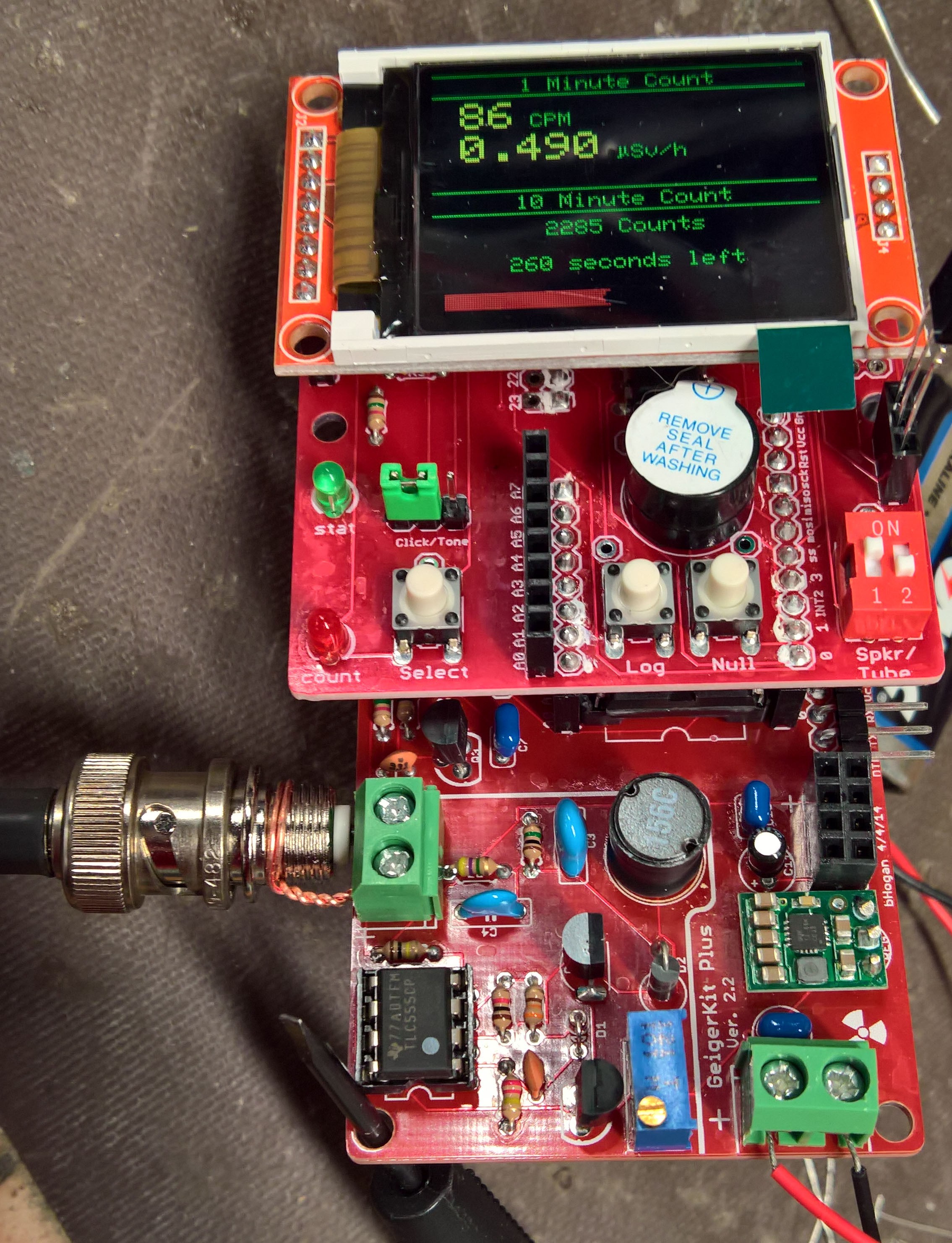
I got clicks! Then it clicked some more. Then it started clicking so much it was nearly a hiss, ignoring the proximity of my sample.
Crap.
My friend had to leave at this point, so I stared at our improvised rigging and wondered if I could simplify the math from a 9-resistor divider to a 10-resistor ladder by using the voltmeter's series resistance as part of the circuit. I looked up the Fluke 115's impedance which is actually kind of hard to find: >10Mohm.
Welp, that makes a nice, clean, 10-resistor 100 Mohm divider, so I hooked it up.
Apparently I had been pumping ~940V through my tube. I hope I didn't hurt it...
With that in place, I then re-set it to ~550V, hooked the tube back up, and, lo and behold, the tube started working! The rate shown in the photo is an accumulation of time both with and without my sample.
Later, thinking about it, I realized that the reason for the massive change was simple: If the meter was 10 Mohm, then the 9-resistor divider was a 10||10+8*10, or 85 Mohm, load, and the voltage I was reading was 5/85 (.05x) of the real value instead of 10/90 (.11x).
Even later I decided to look at the kit instructions again and learned there's yet another problem: even 100 Mohm is a heavy load for the power supply, so it will read ~3/4 of the actual voltage.
I think I'll try a 1 Gohm load before doing much more with the actual tube. Oh well.
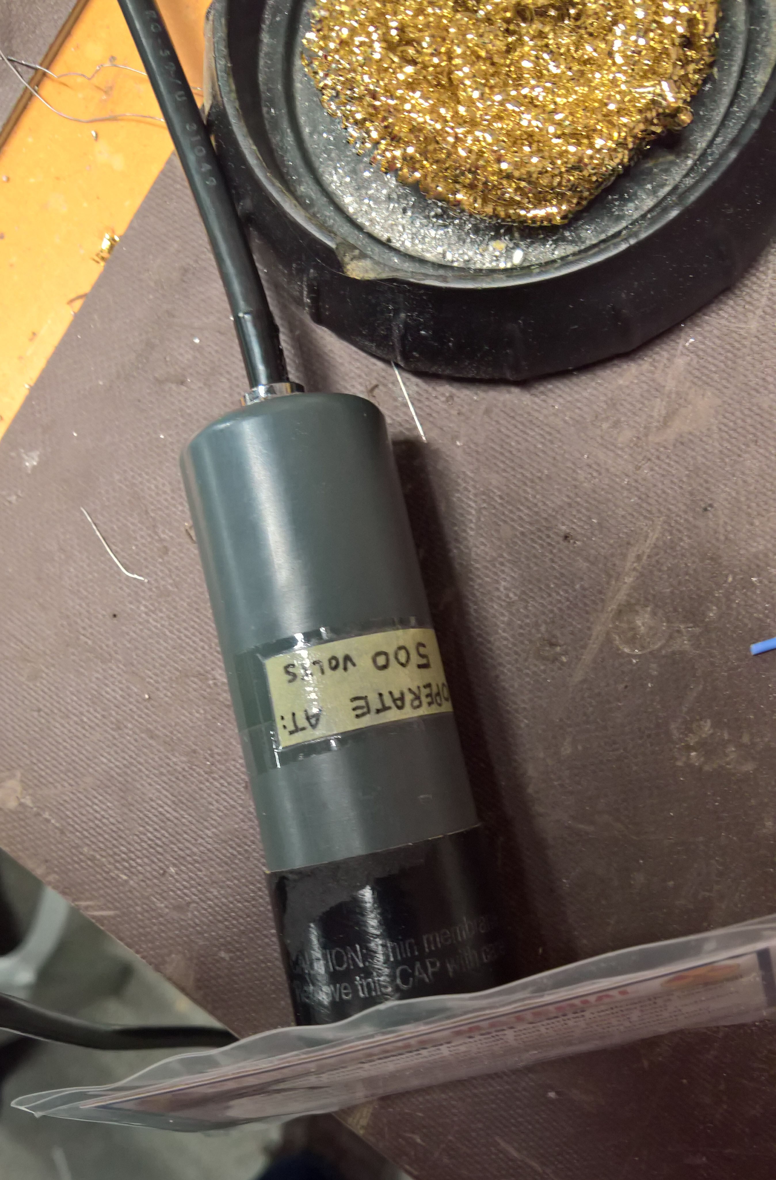
Here's the tube itself. All I know is that it came out of medical equipment, works at 500V, has a mica alpha window, has a BNC connector on RG-59 cable, and was sourced off of eBay by my dad:
I also now know that it is not supposed to operate at 950V. Math is hard, OK? ;)
It also seems to work OK with the BNC shield at +550V.
Side note about the kit: if you use the Display Adapter board, be sure to install *all* 4 of the longer headers at once (just like the instructions say) following the procedure in the instructions. This makes mating the two boards much easier.
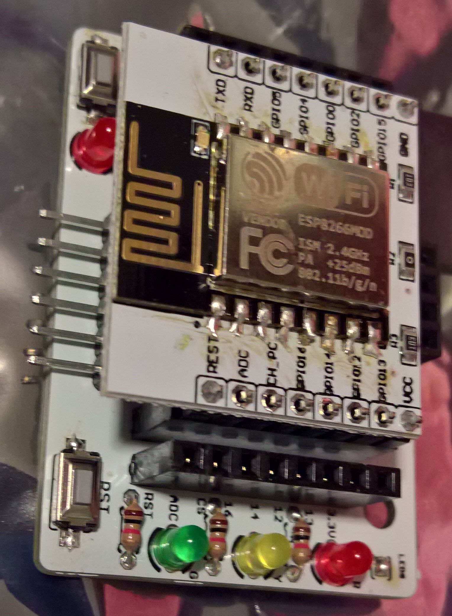
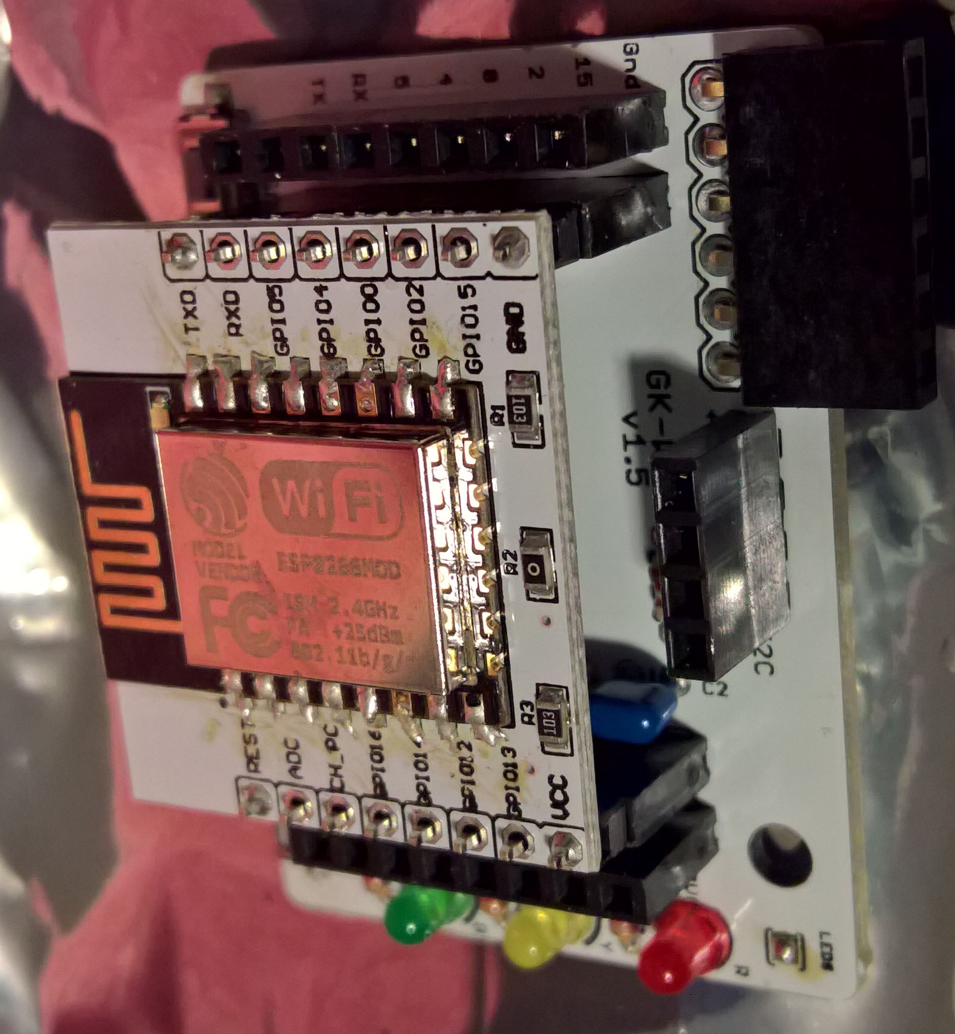
The WiFi kit was quite a bit fiddly to solder; I haven't programmed the ESP8266 yet, so I don't know if the soldering I did on the ESP's module edges actually works.
A short video of the GK Plus + GM tube setup in action with my UnitedNuclear Geiger Counter Test Card:
 Jon Kunkee


 Here's the whole assembly.