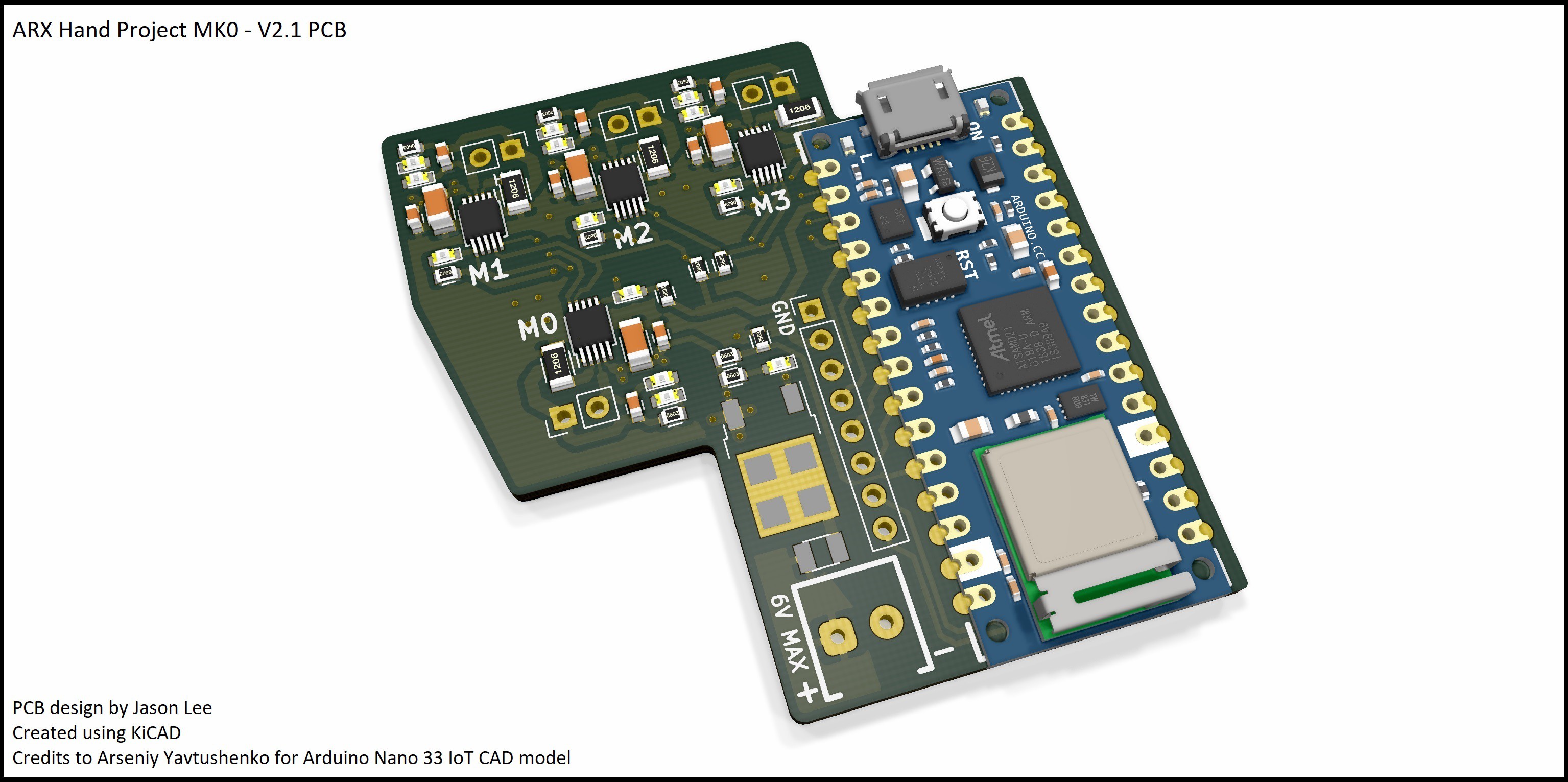
New PCB development with better integration between drivers and microcontroller. PCB now uses Arduino Nano style footprint to allow for change between different microcontrollers, such as the Arduino Nano V3, Nano Every and Nano 33. Reverse polarity, short circuit protection and battery voltage level have also been added with the use of a P-Channel MOSFET and polyfuse.
Features:
- Arduino Nano Footprint
- Reverse polarity protection, P-Channel MOSFET
- Short circuit protection, Polyfuse
- Battery voltage level, through A7 pin
- Screw terminal power input
- Improved spacing for motor connections
- Broken out connections for GND, 3.3V, A0, A1, I2C and TTL Serial
Specs:
- 6V max operating voltage
- I2C motor driver interface
- Battery voltage level = (voltage at A7 pin) * 2
- D2 to D5 are used for limit reading for M0 to M3
- Breakout connections: GND, 3.3V, A0, A1, SDA, SCL, RX and TX
Further Work:
- Better location for breakout connections
- Use of compact wire-to-board connectors
- General PCB design improvements for hand, e.g. smaller footprint, more features, etc.

KiCAD: https://kicad-pcb.org/
Arduino 33 IoT CAD Model: https://grabcad.com/library/arduino-nano-33-iot-1
 Supercell
Discussions
Become a Hackaday.io Member
Create an account to leave a comment. Already have an account? Log In.