-
1Creating the wires to connect the sensor with the D1 Mini
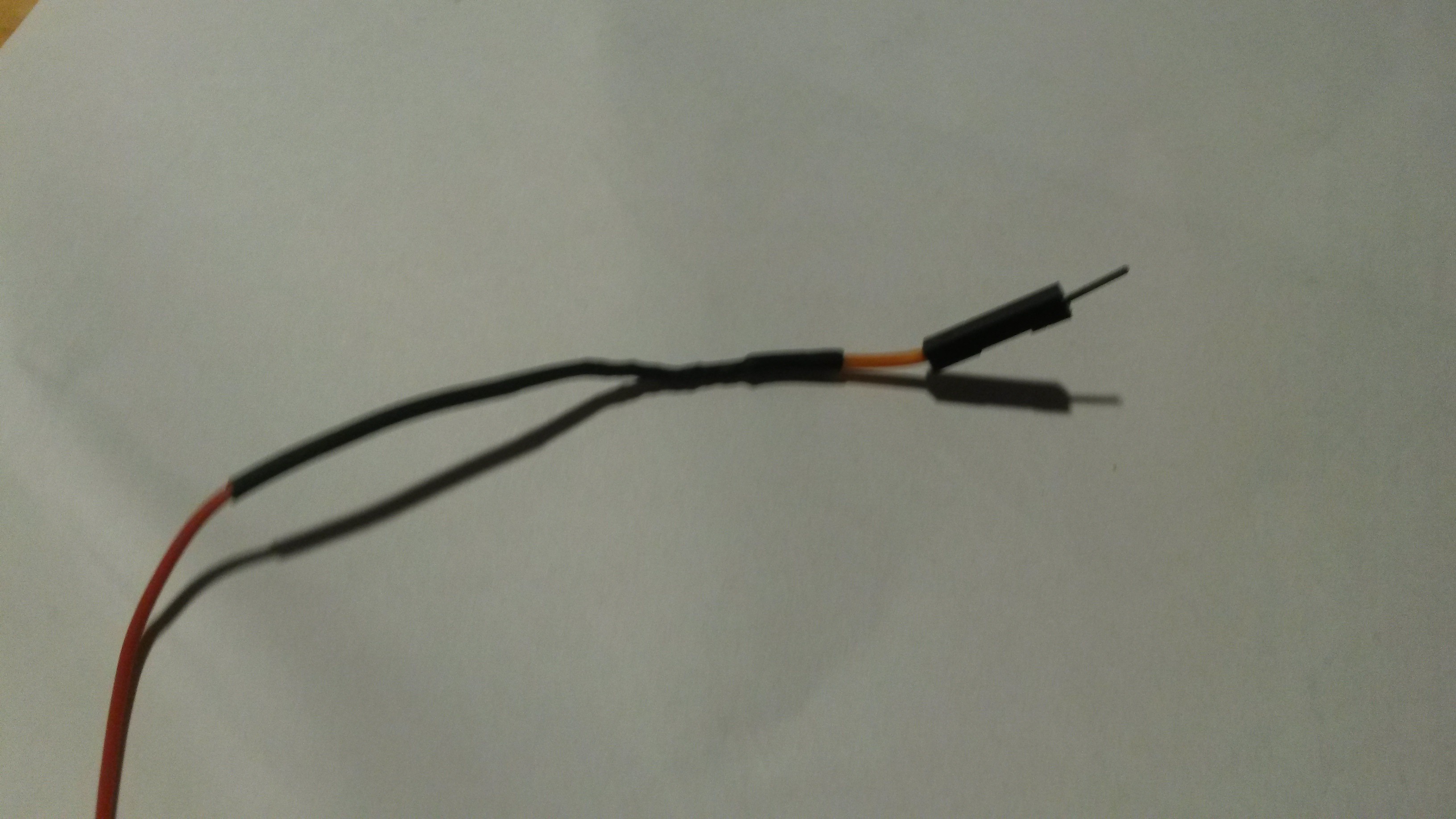
The D1 mini is a cheap microcontroller with a wifi module. It's possible to connect the board with my home Wifi, if I place it next to one of the windows of my garage. The connected Ultrasonic sensor itself has to be placed in front of the garage door though. I had to bridge the distance between my D1 mini and the sensor by tinkering with some wires. That's why I've ordered Copper Wire with different colored isolations (Red and blue). In the end, I've created 4 wires (Echo wire, Trigger wire, VIN wire and a GND wire). I've soldered one half of a Jumper Wire to every end of the individual wires to connect the finished wires with a PCB header (packaged with the D1 Mini) and with the breadboard the D1 mini was placed on. Before doing so, I've put some shrink tube over the longer wires. For this kind of work I recommend a Third hand. The pictures below illustrate what I did and what I've used. Furthermore I've put a paper name tag on every single wire. Besides using red (VIN) and black Jumper Wires (GND) I also use orange colored Jumper Wires as VIN wires and blue colored wires as GND wires.
![]()
![]()
-
2Soldering the PCB and putting everything together
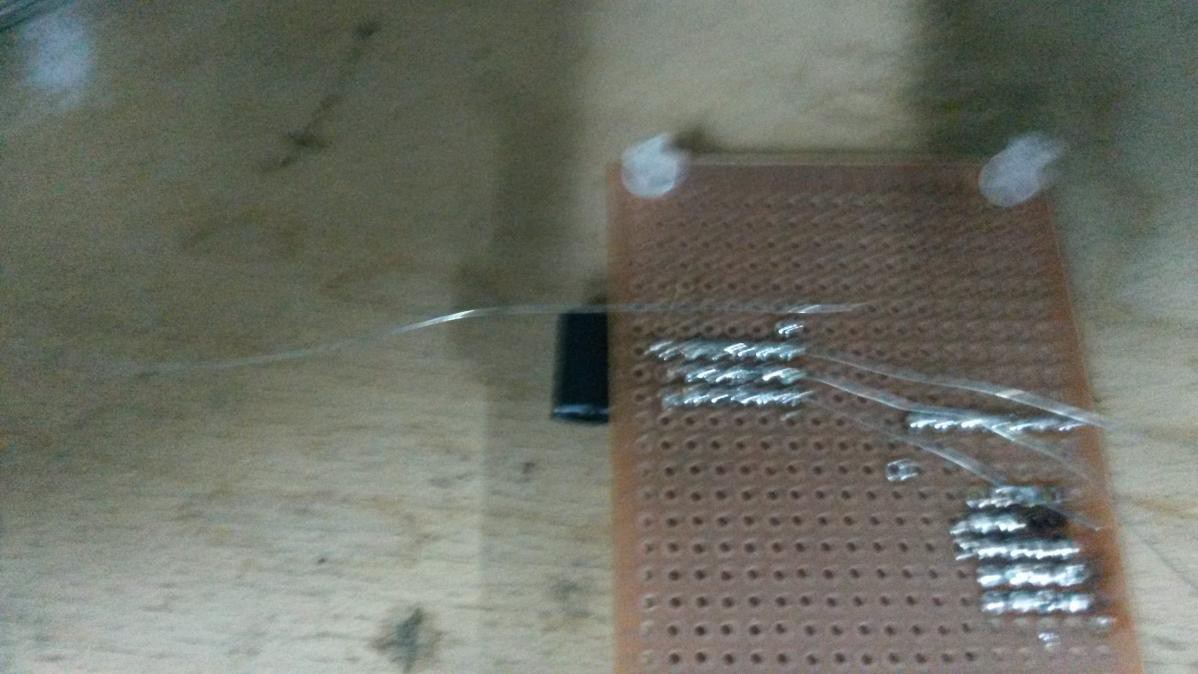
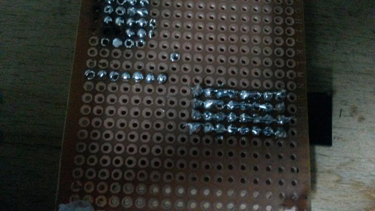
The next step included soldering both headers to a circuit board. I had to use a PCB to make sure, that the Ultrasonic sensor fits into the distribution box. Originally I've wanted to use a breadboard instead, but that didn't work out. Personally I had problems creating soldering lines on the PCB with the solder alone, which came with my new soldering station. That's the reason I've bought plated copper wire to solder the bottom part of the circuit board in a way, which is easier. The following video illustrates the technique well:
![]()
![]()
There is definitely some room for improvement in regards of my PCB soldering skills, but this did the job. With more practice, I should create better looking soldering jobs. :)
The upper left part on the circuit board can be ignored. A week earlier I just tried to get a feeling for soldering on a PCB again.
To make the PCB stand inside my distribution box, I've used the following PCB standoffs. I had to sand off parts of the feet of the standoffs though, so the sensor could fit through the holes I've drilled.
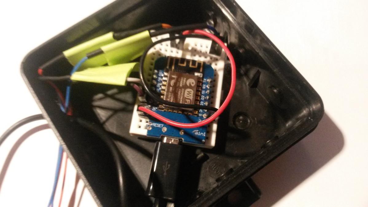
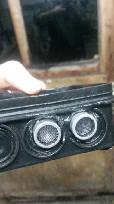
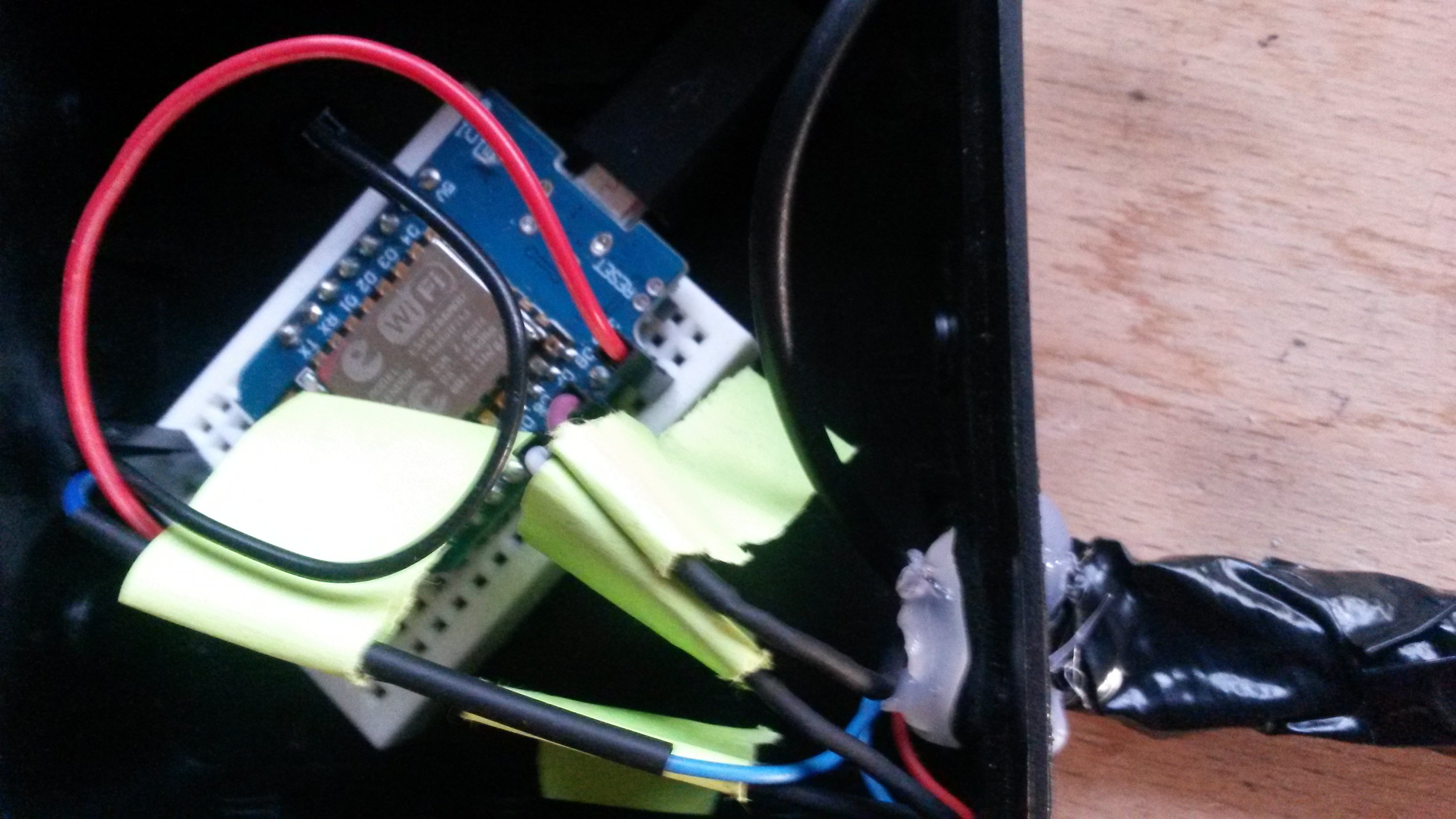
I've bent one header to stick the Ultrasonic sensor into it later on. Additionally I had to bent the pins on the Ultrasonic sensor to connect the sensor to the bent header. Of course I had to drill some holes too. One hole for the wires and 2 holes in the front for the sensor itself. Later on, I've used glue from a glue pistol to close the drilled holes in the sensor box and in the D1 Mini box. The following illustrations show the finished sensor box from the side and the finished D1 Mini box:
![]()
![]()
![]()
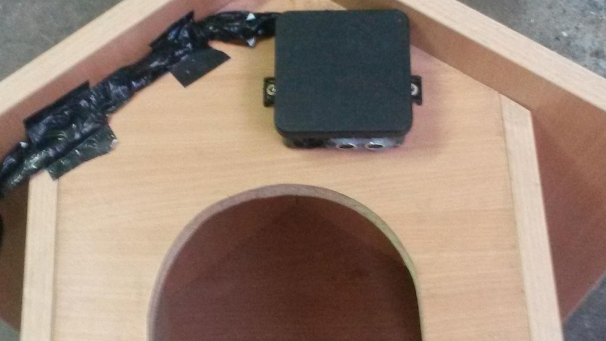
I've put the sensor box under a dog house, which is standing unsuspiciously next to our garage door . That way the sensor box is well hidden. The sensor box itself is aiming towards the garage door.
The usb cable, which is leading out of the D1 Mini box was plugged into a Wall socket battery charger to power the D1 Mini.
-
3Webhook creation
The goal of this project was, that the D1 Mini uses a webhook to send an alert SMS to my phone, if somebody enters my garage. I've used the website IFTTT.com to create a webhook, which provides this service. The following steps describe the process (Note: You need the IFTTT android app to use the method I'm decribing in the following steps):
Step 1: Create an account on the site. Click on your profile picture next to the "Explore" button and then on "Create".
![]()
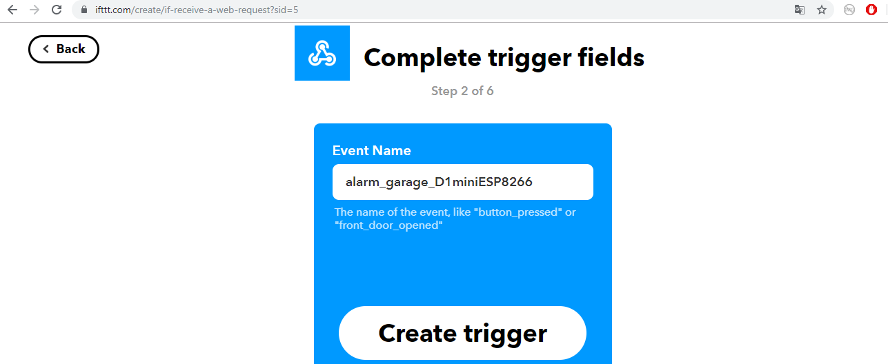
Step 2: Click on the plus symbol and use the search function afterwards. Search for the word "webhook". Click on the Webhook symbol and then on "receive a webrequest". Then it's time to choose an event name. Later on the chosen eventname will be needed in your sketch you will run on your own D1 Mini microcontroller. Create the trigger.
![]()
![]()
![]()
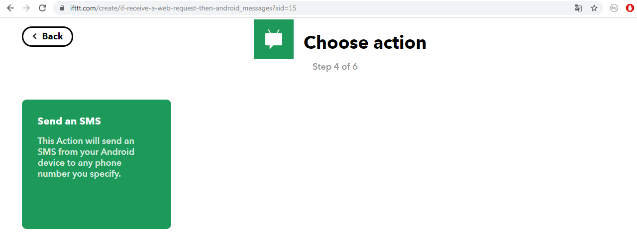
Step 3: After you created the event name it's time to take care of the sms notification. Remember the plus symbol? Now it should appear next to the word "That". Click on the plus symbol and search for "android sms". Follow the instructions and enter the phone number, which you want to use for the sms notifications.
Note: This service requires the IFTTT app for Android.
![]()
![]()
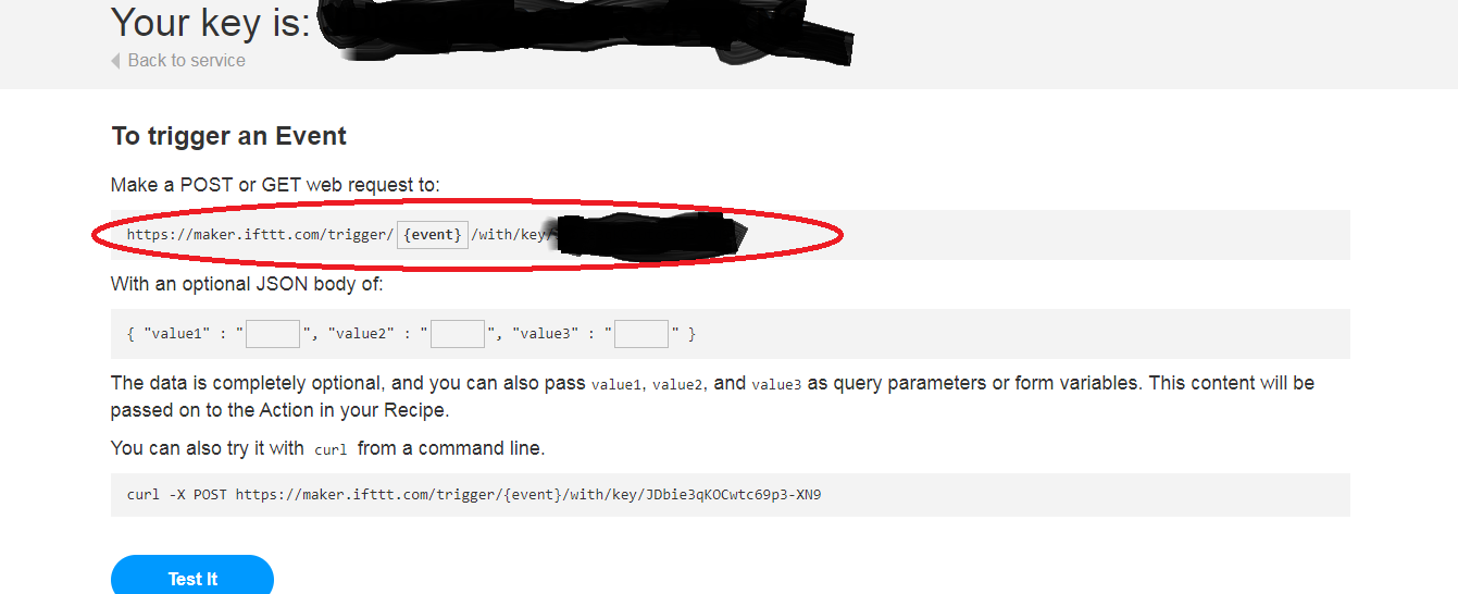
Step 4: The D1 Mini needs to make a web request to fire up the webhook, which we just created. That's why you need to make a web request using a certain link with a key at the end, which is connected to your specific event. To get this key follow the following steps: Click on "IFTTT" on the top left corner > Webhooks > Documentation. On this page you find the URL, which you need to make use of the webhook. The following pictures illustrate the process:
![]()
![]()
![]()
This URL in the last picture is really important. It will be needed in the sketch you will upload to the D1 Mini. Beforehand you can test if everything works though. Just replace YourEventName with your event name and replace YourKey with the real key in the link below:
https://maker.ifttt.com/trigger/YourEventName/with/key/YourKey
A sms will be send to the phone number you've used in step 3.
Additional information: If you want to change the event name or the sms message, just click on your profile picture. Then click on "My applets" and choose the event you want to edit. Afterwards on the top right corner you should find the settings button. Now you can change the event name or the sms message. Don't forget to adjust the event name in your header file arduino_secrets.h (For more information take a look at the section named "Project code")!
-
4Project code
The code of this project includes the following key points:
- measurement of distance between 10PM and 5 AM (watchdog time)
- webhook activation for values greater than the threshold distance (SMS notification)
- D1 Mini as webserver to check measurements through a web browser (On Win 7 use the command arp -a in the Windows Console, if you forgot about the IP of the D1 Mini)
- updating the internal clock through the time server pool (Lost WiFi-connection doesn't affect internal clock)
- WiFi-connection retry, if the connection is lost during the watchdog time
- WiFi module is turned off, when watchdog isn't active
// Useful links
//https://wiki.wemos.cc/products:d1:d1
//https://escapequotes.net/esp8266-wemos-d1-mini-pins-and-diagram/

// Libraries
#include <ESP8266WiFi.h>
#include <NTPClient.h>
#include <WiFiUdp.h>

// Constants
#define trigPin D7  // Trigger to Pin 7
#define echoPin D6  // Echo to Pin 6
const int Starttime = 22; // start for watchdog
const int Endtime = 5;  // end for watchdog
const int watchdogpause = 3600000; // break in ms after alert was triggered
const int threshold = 40;  // distance threshold in cm

// Variables
float duration, distance;
int currentHour;

#include "arduino_secrets.h" // Secret keys and names

///////please enter your sensitive data in the Secret tab/arduino_secrets.h
char ssid[] = WLAN_SECRET_SSID;        // your network SSID (name)
char pass[] = WLAN_SECRET_PASS;    // your network password (use for WPA, or use as key for WEP)
String ifttt_webhook_key = SECRET_IFTTT_WEBHOOK_KEY; // your API key for the webhook
String ifttt_event = SECRET_EVENT;  // your name for the webhook event

const char* hostIftttMaker = "maker.ifttt.com"; // Website, where the webhook exists
String IftttMakerString = "";  // empty String variable for saving

WiFiUDP ntpUDP; // define NTP Client to get time
WiFiServer server(80);  // creating a server object

// You can specify the time server pool and the offset, (in seconds)
// additionaly you can specify the update interval (in milliseconds)
NTPClient timeClient(ntpUDP, "europe.pool.ntp.org", 3600, 60000);

void setup() {
  Serial.begin(115200); // opens serial port, sets data rate to 115200 bps
  delay(10);
  Serial.print("Startup reason:");
  Serial.println(ESP.getResetReason());

  pinMode(trigPin, OUTPUT);
  pinMode(echoPin, INPUT);

  startWiFi();

  server.begin();
  Serial.printf("Web server started, open %s in a web browser\n", WiFi.localIP().toString().c_str());
  Serial.print("Webserver is accessible between ");
  Serial.print(Starttime - 12);
  Serial.print(" PM and ");
  Serial.print(Endtime);
  Serial.println(" AM");
  delay(300000);  // wait five minutes before jumping into the loop

  timeClient.begin();

  Serial.print("Watchdog is ready for patrolling between... ");
  Serial.print(Starttime - 12);
  Serial.print(" PM and ");
  Serial.print(Endtime);
  Serial.println(" AM");
}

void loop() {
  timeClient.update();  // updating the internal clock through time server pool
  delay(1000);
  Serial.println(timeClient.getFormattedTime()); // read from internal clock
  int currentHour = timeClient.getHours(); // read hours from internal clock
  Serial.println(currentHour);

// deactivate the WiFi module to save power, when watchdog isn't active
if ((currentHour >= Endtime && currentHour < Starttime) && (WiFi.status() == WL_CONNECTED)) {
    Serial.println("Internal clock was updated via time server pool");
    Serial.println("Set WiFi module to sleep mode till watchdog starting time");
    stopWiFiAndSleep();
}

// wake WiFi module up, when watchdog is active
  if ((currentHour >= Starttime || currentHour < Endtime) && (WiFi.status() != WL_CONNECTED)) {
    Serial.println("Wake WiFi module up");
    startWiFiAndWake();
  }

  Serial.print("WiFi status: ");
  Serial.println(WiFi.status());

// Watchdog works only daily between starttime and endtime
 if (currentHour >= Starttime || currentHour < Endtime) {

// Write a pulse to the RCW-0001 Trigger Pin
  digitalWrite(trigPin, LOW);
  delayMicroseconds(2);
  digitalWrite(trigPin, HIGH);
  delayMicroseconds(10);
  digitalWrite(trigPin, LOW);

// Measure the response from the RCW-0001 Echo Pin
   duration = pulseIn(echoPin, HIGH);

// Determine distance from duration
// Use 343 meters per second as speed of sound

 distance = (duration * 0.0343) / 2;

// Send measurement to Serial Monitor
  Serial.print("Distance = ");
  Serial.println(distance);
  //delay(500);

  distanceRequest();  // executed, if client (web browser) connects

  // sensor can measure distances between 1 cm and 450 cm
  // alert threshold was a distance of 40 cm in my case
    if (distance > threshold) { // change the distance threshold
      Serial.println(distance);
      Serial.println("Intruder Detected!");
      Serial.println("Sending text notification...");
      Serial.print("Watchdog takes a break for ");
      Serial.print(watchdogpause/(1000*60));
      Serial.println(" minutes");
      SendIftttMaker(ifttt_event, ifttt_webhook_key);  // firing up the webhook
      delay(watchdogpause); // break before loop continues
    }
    //delay(500);
   }
}

// function section
//***********************************************************

// function for starting WiFi connection
void startWiFi() {
  // Bring up the WiFi connection
  WiFi.begin(WLAN_SECRET_SSID, WLAN_SECRET_PASS);
  while (WiFi.status() != WL_CONNECTED)
  {
    delay(500);
    Serial.print(".");
  }
  Serial.println();
  Serial.print("WiFi Connected, IP address: ");
  Serial.println(WiFi.localIP());
}

// function for turning the WiFi off
void stopWiFiAndSleep() {
  WiFi.disconnect();
  delay(1000);
  WiFi.mode(WIFI_OFF);
  WiFi.forceSleepBegin();
  delay(1);
  Serial.println("WiFi module disabled...");
}

// function for wake up and starting WiFi connection
void startWiFiAndWake() {
  WiFi.forceSleepWake();
  delay(1);
  // Bring up the WiFi connection
  WiFi.mode(WIFI_STA);
  WiFi.begin(WLAN_SECRET_SSID, WLAN_SECRET_PASS);
  while (WiFi.status() != WL_CONNECTED)
  {
    delay(500);
    Serial.print(".");
  }
  Serial.println();
  Serial.print("WiFi Connected, IP address: ");
  Serial.println(WiFi.localIP());
}

// function for activating the webhook
void send2web(String thehost, String urlstring) {
  // Use WiFiClient class to create TCP connections
  WiFiClient client;
  const int httpPort = 80;
  if (!client.connect(thehost.c_str(), httpPort)) {
    Serial.println("Connection failed");
    Serial.println("Restart ESP");
    ESP.restart();
  }

  // We now create a URL for the request
  // This will send the request to the server
  client.print(String("GET ") + urlstring + " HTTP/1.1\r\n" +
               "Host: " + thehost + "\r\n" +
               "Connection: close\r\n\r\n");
  delay(4000);
  client.flush();
  client.stop();
  delay(100);
}

// Create url string and put host and url string into the function send2web
void SendIftttMaker(String inIftttEvent, String inIftttMakerKey) {
  IftttMakerString = "/trigger/" + inIftttEvent + "/with/key/" + inIftttMakerKey;
  send2web(hostIftttMaker, IftttMakerString);
}

// function with web page content passed from server to client
 String prepareHtmlPage() {
  String htmlPage =
     String("HTTP/1.1 200 OK\r\n") +
            "Content-Type: text/html\r\n" +
            "Connection: close\r\n" +  // the connection will be closed after completion of the response
            "\r\n" +
            "<!DOCTYPE HTML>" +
            "<html>" +
            "Distance (Old Garage):  " + String(distance) + " cm" +
            "</html>" +
            "\r\n";
  return htmlPage;
}

// function for client request
void distanceRequest() {
  WiFiClient client = server.available();
  // wait for a client (web browser) to connect
  if (client) {
    Serial.println("\n[Client connected]");
    while (client.connected()) {
      // read line by line what the client (web browser) is requesting
      if (client.available()) {
        String line = client.readStringUntil('\r');
        Serial.print(line);
        // wait for end of client's request, that is marked with an empty line
        if (line.length() == 1 && line[0] == '\n')
        {
          client.println(prepareHtmlPage());
          break;
        }
      }
    }
    delay(1); // give the web browser time to receive the data

    // close the connection:
    client.stop();
    Serial.println("[Client disconnected]");
 }
}
Take note that a NTP server provides you the time in UTC. During winter time, the time in Germany is UTC+1. That's why I've chosen 3600 in the following line:
NTPClient timeClient(ntpUDP, "europe.pool.ntp.org", 3600, 60000)The so called header file (.h) with your confidential data:
#define WLAN_SECRET_SSID "xxxxxxxxxxxxxx"
#define WLAN_SECRET_PASS "xxxxxxxxxxxxx"
#define SECRET_IFTTT_WEBHOOK_KEY "xxxxxxxxxxxxxxxxx"
#define SECRET_EVENT "xxxxxxxxxxxxxxxxxx"
In my case it's called arduino_secrets.h. This header file has to be saved in the sketch's folder. arduino_secrets.h includes the information you need to have access to the chosen Wifi connection. Furthermore you have to include the webhook key and your event name in this header file (Take a look at the section Webhook creation to get an idea about where to find this information)
Examples:
Console output, after uploading the sketch:
![]()
Console output, when watchdog isn't active and Wifi module is turned off:
![]()
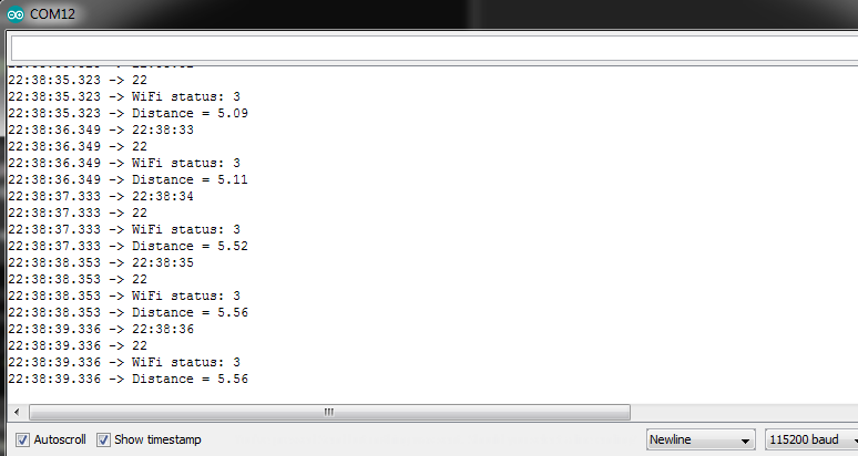
Console output, when watchdog is active between 10 PM and 5 AM:
![]()
Copying the provided IP and pasting it in a web browser should result in the following page:
![]()
SMS Garage Alert system using an Ultrasonic sensor
ESP8266 SMS Garage Alert system using a RCW-0001 Micro Ultrasonic Sensor and a Webhook (IFTTT.com and IFTTT android app)







Discussions
Become a Hackaday.io Member
Create an account to leave a comment. Already have an account? Log In.