-
Hop, Skip and Jump
10/24/2019 at 17:29 • 3 commentsThis week I am working towards getting my pet project, SIMPL working on the Suite-16 simulator.
I am making good progress with the main routines that handle decimal number entry and decimal number printing. These have been relatively easy to code, and the codesize compares with the equivalent code written in MSP430 assembly language.
The next thing I need to code up are the three routines that will provide the mechanics of the interpreter.
Assembling code by hand is not too difficult, but it helps if you keep a modular approach - and each module has only one entry point and one exit point. It takes more time to plan each module, and then test it - than it does to hand assemble. So for the moment I am not overly concerned that I don't have a full assembler.
Modular code is the approach taken by Forth. You are encouraged to write short routines that only require a few input variables that are taken off the stack, and in turn will calculate some output result that is placed back on the stack. The stack is the all important communicating pipeline between the functional modules.
Whilst SIMPL is by no means anything like a full Forth, it does follow closely with some of the techniques used in the interpreter, but the dictionary that is fundamental to Forth is replace with a simple jump table. This makes it possible to have a working SIMPL kernel operating in fewer than 1000 bytes of code.
The Command Interpreter
Ward Cunningham who wrote Txtzyme, the precursor to SIMPL, described his interpreter as a switch-case statement contained within a loop.
I now need to devise an efficient switch statement mechanism for Suite-16, as this is central to the whole functioning of the command interpreter.
The switch statement is given an input value which it translates by a look-up table mechanism to an output value, and this output value is used as a jump address for the program execution.
Commands
Whilst there are 96 printable ascii codes to be used as commands, we are unlikely to have to use all of them in the jump table. First we can discount the numerical characters as these are handled separately by the number entry routing. Capital letters are reserved for User Functions or variables, so they will also be handled differently. That just leaves 26 lower case characters and 34 other symbols. The jump table has already reduced in size from 96 to 60 entries. It may be possible to reserve 60 words of the zeropage to accommodate the jump table, leaving 196 words for essential code, user variables and structures such as the data stack and return stack.
The jump mechanism needs some clarification. With Suite-16 we can embed an 8-bit jump address into the lower byte of the instruction. This however is very useful for accessing addresses on the zeropage, and we will need to find an alternative method to access the code words that are more likely to be located outside of page 0.
The jump table will contain a list of addresses, which are the start addresses for all of the command routines. For example if our accumulator currently holds the ascii character "p" 0x70 and we want to used this to invoke the printnum routine which for example starts at address 0x0100, we need to create a table in memory which at address 0x70 contains the value 0x0100. We can get this address back into the accumulator and then jump to it.
Trampoline Jumps
Suite -16 is currently only using an 8-bit jump address which is stored in the payload section of the instruction. If we extend this to a 16-bit jump, the target address will be held in the word following the jump instruction. We can use the accumulator to overwrite this target address, so we can effectively jump to an address that is held in the accumulator. This currently will have to be done in a two stage process, sometimes called a Trampoline Jump.
Let's assume that the accumulator holds 0x70 the letter p, and we want to jump to address 0x0100 that is held in the lookup table. We can use the indirect register addressing mode to access the table, using register R1 as a pointer. Our trampoline will be placed at locations 0x80 and 0x81ST R0, R1 // R1 now contains 0x70 LD R0, @R1 // R0 contains 0x0100 SET R1, 0x81 // The trampoline's target address location ST R0, @R1 // store 0x0100 at location 0x81 JMP 0x80 // Jump to 0x80 where the trampoline jump instruction is locatedThis method is quite clunky and it takes 6 instructions to direct the program flow to the printnum routine.
It would be better if there was an easy way of doing a direct jump based on the contents of the accumulator, but with very little additional hardware overhead.
Fortunately we already have the means to modify the bottom 8-bits of the program counter as it is used by our call and branching methods. It should be relatively straightforward to adding a new instruction in the form of JMP @R0.
Our look-up code then becomes much simpler:
ST R0, R1 // R1 now contains 0x70 LD R0, @R1 // R0 contains 0x0100 JMP @R0 // Program jumps to address 0x0100 -
printnum_2
10/24/2019 at 15:41 • 0 commentsPrintnum is the routine that converts a 16-bit binary number to a 5-digit ascii string.
I covered it a few days ago - but was not happy with the large blocks of code that were repeated 4 times over.
Now that I have the CALL and RET subroutine mechanism working, I decided to rewrite the routine using one subroutine labelled "Decimate" that is called 4 times, each time with a different decimation factor (10,000, 1000, 100 and 10) stored in R1.
The result is much simpler and shorter code - and easier to understand. It is 39 words long, whereas its predecessor was 84 words.
Here is the new version printnum_2
// 0x0010 ---------------------------PRINTNUM_2----------------------------------------- // R1 = Decimation Value // R2 = digit // R3 = 0x30 // R4 = temporary storage for accumulator (decimated value) 0x1200, // SET R2, 0x0000 0x0000, 0x1300, // SET R3, 0x0030 0x000, 0x1100, // R1 = 10,000 0x2710, 0x082C, // CALL decimate 0x1100, // R1 = 1000 0x03E8, 0x082C, // CALL decimate 0x1100, // R1 = 100 0x0064, 0x082C, // CALL decimate 0x1100, // R1 = 10 0x000A, 0x082C, // CALL decimate // 0x0020 --------------------------------------------------------- 0xA300, // ADD R0, R3 to make a number 0x0C00, // putchar R0 0xB300, // SUB R3 to restore accumulator 0x1000, // SET R0, CR 0x000D, 0x0C00, // putchar R0 CR 0x1000, // Set R0, LF 0x000A, 0x0C00, // putchar R0 LF 0x0000, // BRA START 0x0F00, // NOP 0x0F00, // NOP // 0x002C ------------------------Decimate-------------------------------- 0xB100, // SUB R1, :Decimate 0x0230, // BLT 0x30 0xE200, // INC R2 0x002C, // BRA 0x02C // 0x0030 --------------------------------------------------------- 0x3400, // Store R0 in R4 0x2200, // MOV R2, R0, 0xA300, // ADD R0, R3 to make a number 0x0C00, // putchar R0 0x2400, // Get R0 back from R4 0xA100, // ADD R1 adds DEC value to restore R0 0x1200, // SET R2,0 Reset R2 0x0000, 0x0900, // RET -
Number
10/24/2019 at 11:58 • 0 commentsHere's the second major routine needed to make working with decimal numerical input possible.
Get_Number parses through the text input buffer looking for numerical ascii codes that fall in the range 0x30 to 0x39.
These correspond to the digits 0 to 9, so the first thing you must do is subtract 0x30 (decimal 48) from the incoming character to turn it into a decimal digit. It is convenient to preload one of the working registers with 0x30 (and keep it there) and in this application I choose R3 to contain 0x30.
Once you have your first decimal digit in the accumulator, you need to multiply it by 10. Then you take your second digit, add it to the sum in the accumulator and multiply by 10 again. You continue this process until you have added the last digit to the total, and the accumulator will hold the decimal equivalent of the numerical string in the text buffer.
However, you have to know where to stop multiplying by 10, so that the last digit in the string is just added . To do this you have to continuously look ahead at the next character in the input buffer and determine if it is a numerical character or not. If it's not a number, you skip the times 10 multiplication and jump to a final addition.
Here is the resulting code - hand assembled for Suite -16.
     // 0x0090 --------------------------------NUMBER-------------------------------------

        0x1300,     // SET R3 0x30   Preload R3 with decimal 48
        0x0030,
        0x1200,     // SET R2, 0x0A  Preload R2 with decimal 10
        0x000A,

        0x1100,     // SET R1, 0x0200    text buffer start
        0x0200,
        0x4100,     // LD AC, @R1  get first character from buffer
        0x3400,     // Store R0 in R4

        0xE100,     // INC R1
        0x4100,     // LD AC, @R1  get next character - and test to see if it is a number
        0xB300,     // Subtract R3  Is it bigger than 0x30?
        0x02AA,     // BLT Not a Number

        0xB200,     // Subtract R2  0x0A
        0x03AA,     // BGE Not a Number
        0x2400,     // Get original character  R0 back from R4
        0xB300,     // Subtract R3  to form a digit


     // 0x00A0 ---------------------------------------------------------------------

        0xA700,     // get the accumulating total  from R7 - ready to multiply
        0x3500,     // Store R0 in R5  Digit is now in R5
        0xA500,     // ADD R5  Accumulator R0 = (2 * digit)
        0x3600,     // Store R0 in R6  - this is the "Times 10" routine

        0xA600,     // ADD R6   4 X
        0xA600,     // ADD R6   6 X
        0xA600,     // ADD R6   8 X
        0xA600,     // ADD R6   10 X

        0x3700,     // Store R0 in R7   R7 is accumulation of all the digits multiplied by powers of 10
        0x0096,     // BRA 0x0096 Get the next digit
        0x0F00,     // Not a number  address = 0xAA
        0x2400,     // Get last digit  R0 back from R4

        0xB300,     // Subtract R3
        0xA700,     // Add the accumulated sum from R7 - decimal number is now it R0
        0x1700,     // Don't forget to clear R7
        0x0000,

     // 0x00B0 ---------------------------------------------------------------------

        0x0802,     // CALL 0x0002  PRINTNUM
        0x0000,      // BRA START
Incidentally, a functionally similar routine coded in MSP430 assembly language took 25 16-bit words (although in MSP430 ASM it's only 16 instructions). I'm quite happy with this implementation by comparison - as I use 8 words to initialise registers.
One thing that would be useful in the instruction set - would be immediate operations on the accumulator with the short-constant held in the Payload-byte.
There are several occasions when handling ascii characters, that you want to test against some value and modify the contents of the accumulator. Being able to add or subtract an 8-bit literal from the accumulator without having to use another register would be a big advantage.
Whilst some might think that hand-assembly must be some form of mental masochism, it's actually not that difficult.
Actually writing the code takes surprisingly little time. What does take the time is thinking how to write the algorithm efficiently using the instructions and registers available, and the time spent recompiling and testing the code.
You will see that I am listing my code in little blocks of 4 instructions, with a commented dividing line between every 16 instructions.
This allows me to arrange the code into easily manageable blocks and keep tally of exactly what address the instruction will be coded at.
Routines must for the moment be placed at fixed addresses ( non-relocatable) as I only have absolute branching. It's a minor inconvenience for the moment, and it will probably be changed when I revisit the branching mechanism.
-
printnum
10/22/2019 at 21:20 • 2 commentsprintnum is essential to any computer system. It takes in a 16 bit integer and prints that as a series of ascii characters to the terminal.
My first attempt was very cumbersome - as I am just starting to learn the assembly language, so I tend to go for the brute force and ignorance approach.
The algorithm works by decimation - we know its a 16-bit number with a maximum value of 65535.
Start by subtracting 10,000 until the number is <0
Count the number of times you subtract 10,000. That will give you the most significant digit. Convert this to ascii and output to the terminal.
Restore the remainder and subtract 1000 until you go below 0, that gives the next digit.
Repeat this for 100, 10 and 1.
The code is flawed - as it bombs out with incorrect ascii characters at 42767 (that's 32767 + 10000 - so clearly a big hint).
The whole routine of inline code including CRLF and incrementing counter is 84 words long.
There are 4 repeated sections of 11 instructions that could be converted to a sub-routine.
R3 is set to a value of 48, four times during the routine. it could be done once at the start saving 6 instructions.
(On the MSP430 I got it down to 33 instructions). More optimisation is possible, and will be done later - but this is a start and proves that I can print out decimal numbers on Suite-16.
Simulating on Various Dev Boards
I have run this code on the MSP430 version of the simulator (clocked at 16 MHz) It takes about 52 seconds to count from 0 to 32768 and output those 5 digits plus CR LF to the screen.
With the simulator running on the 400MHz STM32H743 Nucleo and at 921600 baud the same code for outputting 0 to 32768 is about 3 seconds!
0x1000, // SET R0, 0x0000 0x0000, 0x1100, // SET R1, 0x2710 10,000 0x2710, 0xB100, // SUB R0, R1 :10K addr = 0x04 0x0208, // BLT 0x08 END10K 0xE200, // INC R2 0x0004, // BRA 0004 0x3400, // Store R0 in R4 addr = 0x08 0x2200, // END10K MOV R2, R0 0x1300, // SET R3, 0x30 0x0030, 0xA300, // ADD R0, R3 to make a number 0x0C00, // putchar R0 0x2400, // Get R0 back from R4 0xA100, // ADD R1 adds 10,000 to restore R0 0x1100, 0x03E8, // R1 = 1000 0x1200, // SET R2,0 Reset R2 0x0000, 0xB100, // SUB R0, R1 :1K address 0x14 0x0218, // BLT 0x18 END1K 0xE200, // INC R2 0x0014, // BRA 0x0014 0x3400, // Store R0 in R4 addr = 0x18 0x2200, // END1K MOV R2, R0 0x1300, // SET R3, 0x30 0x0030, 0xA300, // ADD R0, R3 to make a number 0x0C00, // putchar R0 0x2400, // Get R0 back from R4 0xA100, // ADD R1 adds 1000 to restore R0 0x1100, 0x0064, // R1 = 100 0x1200, // SET R2,0 Reset R2 0x0000, 0xB100, // SUB AC, R1 :100 addresss 0x24 0x0228, // BLT 0x28 END100 0xE200, // INC R2 0x0024, // BRA 0x0024 0x3400, // Store R0 in R4 address = 0x28 0x2200, // END100 MOV R2, R0 0x1300, // SET R3, 0x30 0x0030, 0xA300, // ADD R0, R3 to make a number 0x0C00, // putchar R0 0x2400, // Get R0 back from R4 0xA100, // ADD R1 adds 100 to restore R0 0x1100, 0x000A, // R1 = 10 0x1200, // SET R2,0 Reset R2 0x0000, 0xB100, // SUB AC, R1 :10 addresss 0x34 0x0238, // BLT 0x38 END10 0xE200, // INC R2 0x0034, // BRA 0x0034 0x3400, // Store R0 in R4 addr = 0x38 0x2200, // END10 MOV R2, R0 0x1300, // SET R3, 0x30 0x0030, 0xA300, // ADD R0, R3 to make a number 0x0C00, // putchar R0 0x2400, // Get R0 back from R4 0xA100, // ADD R1 adds 10 to restore R0 0x1100, 0x0001, // R1 = 1 0x1200, // SET R2,0 Reset R2 0x0000, 0x1300, // SET R3, 0x30 address = 0x44 0x0030, 0xA300, // ADD R0, R3 to make a number 0x0C00, // putchar R0 0xB300, // SUB R3 to restore accumulator 0x1000, // SET R0, CR 0x000D, 0x0C00, // putchar R0 CR 0x1000, // Set R0, LF 0x000A, 0x0C00, // putchar R0 LF 0x1200, // SET R2,0 0x0000, 0xE500, // INC R5 0x2500, // LD R0, R5 0x0002 // BRA 0002 -
Keep it Simple
10/22/2019 at 14:31 • 0 commentsHaving reached the point of getting the Suite-16 simulator to run "Hello World!" and print ascii characters to the serial terminal, I have paused for thought for a couple of days to contemplate my next step.
I started reading up on various Forth implementations, and realised that I was not quite ready to take on the complexity, but set myself an easier task, to achieve motivation and more experience working with this new alien instruction set that I created in barely a week.
A typical Forth implementation can be between 4K and 8K bytes, and so I am looking for something a lot simpler to test the instruction set - and fortunately I have the very thing in my toolbox.
Back in May 2013, I came across Txtzyme by Ward Cunningham. Txtzyme is described as a nano-interpreter for DIY Domain Specific Languages. This might sound a bit complicated, so I prefer to call it a tiny-Forthlike language with a kernel that will fit into about 1K bytes.
Txtzyme consists of a case statement contained within a loop, which is more or less exactly what my Suite-16 simulator consists of.
Txtzyme receives serial ascii characters one at a time from an input buffer and uses them to invoke certain functions. Originally Txtzyme only had 13 commands - and these were generally used to control the I/O found on the Arduino board.
I very quickly realised that there are 96 printable ascii characters, and all of them could be used as an individual comma commands. All of a sudden we have an instruction set for a virtual machine with up to 96 instructions.
So starting with the basic Txtzyme interpreter commands, I added math functions, conditional branching and most importantly I borrowed from Forth the idea of the colon definition. I now had the basis of a tiny extensible language - so I gave it a name: SIMPL (serial interpreted minimal programming language) - because everybody enjoys a corny acronym (not).
I developed a version of SIMPL in C++ using the Arduino IDE and ported it to several popular microcontrollers including AVR, ARM and MSP430. In fact almost all of the microcontroller boards I have developed in the last 5 or 6 years - SIMPL is usually the first thing I load onto them.
SIMPL is my own private indulgence, it's not a proper grown-up language and probably never will be. It's an old, familiar friend who assists me during the "bring up" phase of any new hardware I have developed.
SIMPL is a serial command interpreter - if you receive this command, invoke this function then return to the interpreter loop.
Some more ancient history (dull but relevant)
When porting SIMPL to the MSP430 LaunchPad using Energia - I rapidly became aware that the Arduino built in functions - such as Serial.print() and Digital.write() were slow and very inefficient in their use of program space. I decided to write my own functions for serial input and output (getchar and putchar) and also for manipulating the digital I/O.
By using my own routines I managed to shave thousands of bytes from the code size needed for SIMPL. At that time Hackaday was running the "1K Byte Challenge" for the best application written in 1K bytes of code. Whilst I didn't enter, it inspired me to learn sufficient MSP430 assembly language - so I could implement SIMPL in assembly. Most of this happened over the Christmas break of 2016, so by early January 2017 I had a usable version of SIMPL running in under 1K bytes of MSP430 assembly.
So almost 3 years on, I have the need to port SIMPL to an unfamiliar new target - Suite-16. Fortunately, Suite-16 is a 16-bit machine and quite a lot of the addressing modes of the MSP430 have been adopted.
Whilst the Suite-16 instruction set does not allow inter-register moves or operations - the Accumulator always forms one operator, it does have sufficient mechanics to implement the SIMPL language.
What is Needed?
SIMPL is implemented using just three top level routines which form the interpreter:
textRead: Get a serial character from the UART and store it in the input buffer
textCheck: Check if the character is a colon : - if so store the remainder of the line of text at a specific address
textEval: Use the ascii value of the character to index into a jump table and pick up the address of the code to be executed
So for example if I type p followed by return, the ascii value of p (0x70) is used to locate a value in the jump table which is used as the address where the routine associated with p is located. This code is then executed and program control returns to textRead. because we are dealing with single ascii character commands - we can choose them to have a high mnemonic value. p was chosen to stand for printnum and the code associated with it prints the top member of the stack as a decimal number to the serial port.
With 96 printable ascii characters I had to devise a plan to keep things memorable.
Lower case characters would be used for some native function that was included within the SIMPL kernel.
Upper case characters would be used primarily for User Defined functions
Symbols such a punctuation marks and arithmetic characters would be used to invoke instruction primitives
Other Essentials
In order to automate the mechanics of SIMPL, I needed a few basic helper functions.
As we are dealing with (only) serial input and output, I needed the equivalent of getchar and putchar.
Next I needed the ability to interpret a sequence of ascii characters and see if they were numerical digits. If so, the string would be converted to a 16-bit number and placed on the stack. This function is called "number".
For numerical output, I needed the reverse process - take the contents of the top of stack and print it out in ascii as a decimal number. This routine is called printnum - described above.
With the 3 routines that form the interpreter, and the helper routines, the rest of SIMPL becomes one large jump table that access a bunch of functions.
Implementing SIMPL on Suite-16
Well that's my task for the rest of this week. I will start by coding "number" and "printnum" in Suite-16 assembler, and when I get these working and fully tested, I can start on the routines that form the interpreter. With the interpreter core and jump table in place, I can start writing as many of the functions as I think I need. Maths functions, text string output and the program flow structures such as looping will probably be the first to be coded.
I have blogged a lot about SIMPL over the years - most of it unread.
-
Henceforth
10/20/2019 at 15:07 • 0 commentsOver the last few weeks, I have realised that the inspiration for my Suite-16 project most definitely has it's origins firmly rooted in the mid-1960s, a bit like me really......
I have illustrated some of my posts with hardware details of the PDP-8, PDP-11, Data General Nova and the IBM 1130 - all of which appeared in the period 1965 to 1970.
This weekend I am trying to chart out the direction this project will head in - based on my experience and skillset.
It's probably a given that there will never be a C-compiler for Suite-16. It's also unlikely that there will ever be a BASIC implementation, unless I follow the same course as the Gigatron TTL computer and first emulate a 6502 or Z80 processor.
So where does that leave this project without an obvious route to a high-level language? (ShitCreek && !Paddle) ?
Given that the technology of this project is currently hovering somewhere between 1965 and 1975, a contemporary solution to this problem would be Charles H. Moore's Forth Language.
First - some ancient history
Back in the Fall of 1981, a school friend told me about a new language that he had read about in Byte Magazine. Neil was the archetypal Geek who had told me about Z80 assembly language a couple of years earlier. At that time I lived on the Isle of Man - a small Island in the middle of the Irish Sea, which, technology-wise, was clearly a few years behind the times. Neil told me about Chuck Moore and Radio telescopes and a whole lot of geeky stuff I didn't understand. It almost seemed heretical that he was telling me about another language other than BASIC - because clearly that was the only thing I had encountered on the home computers of the day.
Some 2 years later I bought a ZX Forth ROM for my ZX81, and then in a surplus sale, a Jupiter ACE. I dabbled in Forth but never really got off the starting grid.
After University, about 1987, and working for BBC Research Department, I bought one of Chuck Moore's Novix NC4016 Forth cpu development boards. This was the fastest cpu IC when it appeared in 1985 - and could outpace an 80286 manifold.
Despite my exposure to Forth at some key points in its evolution, I never seemed to practice the art to the point of becoming competent.
So after almost 40 years my Forth skills are about as weak as my verilog and C skills - and part of the purpose of this project is to try to make amends and strengthen some of my former weaknesses.
And So Forth
Forth is a problem solving tool and integrated programming environment. It is self hosting, compact and versatile. It's also probably the most obscure programming language that you have ever encountered.
Forth evolved in the late 1950s and throughout the 1960s, and until 1970 was the exclusive programming environment of Chuck Moore.
It was commercialised by Forth Inc. throughout the 1970s and became mainstream by 1980, as featured in the August 1980 edition of Byte Magazine.
Forth is based on a 16-bit virtual cpu model that can be implemented on almost any minicomputer, microprocessor or microcontroller. It is ideal for standalone projects where memory and I/O resources are limited.
Forth may be implemented in 8K bytes of source code, or where space is limited a working kernel can be crafted into fewer than 1K bytes.
Moving Forth
It is my intention to use Forth to help solve my immediate computing problem - that is the design, construction and commissioning of a working 16-bit computer system.
As it's Sunday, I will keep this log brief. Expect future updates in due course.
-
Hello World!
10/19/2019 at 14:42 • 0 commentsTradition states that the first thing you get a new computer to do is print out the exclamation "Hello World!"
To reach this point you need to have most of your cpu (or simulator) working, including correct instruction decoding, memory access, various addressing modes, conditional branching and some means to examine the contents of the registers.
I'm pleased to say that after a few days work of defining the instruction set, writing a simulator, an assembly tool and general documentation, Suite-16 has uttered it's first exclamation.
        0x1100,     // SET R1, 0x06
        0x0006,
        0x4100,     // LD R0, @R1
        0xE100,     // INC R1
        0x0103,     // BNZ 03
        0x0000,     // BRA 00
        'H',
        'e',
        'l',
        'l',
        'o',
        ' ',
        'W',
        'o',
        'r',
        'l',
        'd',
        '!',
        '\n',
        0x0000
The final 0x0000 at the end of the string when loaded into the accumulator will cause the BNZ to be ignored and so the program loops back to the beginning with the BRA 00 instruction.
-
Simple Assembly Tool
10/18/2019 at 19:08 • 2 commentsNow that I have got a basic simulator running in C, I can work towards proving the Instruction Set.
However hand assembly of 16-bit instruction words gets a bit tedious - even though the bytecodes are trivial.
I decided that I would hack together a barebones tool that would help me assemble instructions from either text typed at a terminal, or sent from a text file using a terminal program such as TeraTerm.
The first thing to do was to establish a few rules:
To make the job of writing the assembler easier, I really only wanted to parse single characters - rather than the more conventional mnemonics that are usually 3 of 4 character strings - like ADD and CALL.
All of the mnemonics would be assigned a single character - which for arithmetic and logic operations is all very familiar
ADD becomes +
SUB becomes -
AND becomes &
OR becomes |
XOR becomes ^
INV becomes ~
So that's the arithmetical and logical instructions mostly taken care of apart from INC and DEC.
The next task was to allocate single character pseudonyms to my register set R0 to R15.
These would each be designated a capital letter starting at A (a logical choice for the Accumulator) and ending at P, which happens to be the Program Counter. Anyone familiar with 8080 or Z80 code will be quite happy using B, C, D, E, F, H, L, M etc. All I have done is add a few more register names such as G, I, J, K, N and O.
Personally, I find it much easier to remember alphabetical names rather than numbers - J and K are good choices for loop counters and M as a memory referencing register like on the 8080. They can always be changed later depending on the application, I might want to call my Stack Pointer S and my Return Stack pointer R at some later date.
The assembly language syntax will be minimal - just enough to get the job done. A register is refered to by it's name followed by some operator. As most of the ALU operators involve a register plus the accumulator as the destination we can omit the A.
B+ ADD B to A.
B} Move B into A direct register addressing
B{ Move A into B
B! Store A at the address given by B - these are indirect register addressing using fetch @ and store ! symbols borrowed from Forth
B@ Load A from the address given by B
Numeric constants (immediate addressing) use the # - which is borrowed from the LIT word in Forth
1234#B Load B with 1234 which follows in the next memory location
234#B Load B with the short constant, which is found in the payload byte
We now have to dig a little deeper for meaningful symbols
B' INC B
B, DEC B
B\ POP an item off the stack into A, where B is used as the stack pointer
B/ PUSH an item onto the stack, using B as the stack pointer
$ Identify the following number as hexadecimal
127= Branch if A=0 to zeropage address 127
126< Branch if A<0 to zeropage address 126
125> Branch if A>0 to zeropage address 125
I have managed to implement this in less that 200 lines of C code. This is enough to prove the concept and show that the correct instructions can be assembled from the limited syntax. More features such as labels, origins etc can be added when required.
-
Ideas and Influences
10/17/2019 at 13:20 • 0 commentsSuite-16 has been on the back-burner for a number of years, distilling my thoughts slowly and absorbing the deep aromatic influences of past generation computer hardware.
A Little History
One of my main influences is the PDP-8 which became the first mass-market minicomputer in 1965 - the year I was born.
With an estimated 50,000+ machines sold over its 10-15 year lifecycle, it was the first of the accessible minicomputers, pre-dating the microprocessor by almost a decade.
It evolved out of the earlier PDP-5 (1963) - a minimal 12-bit design, which very nearly was not a computer at all. With just 8 instructions, 4K words of core memory and a memory cycle time of 6 microseconds, a 12-bit addition took 3 cycles or 18uS to complete.
Despite its limitations, the PDP-5 was the first of the DEC machines to exceed 1000 sales, and it convinced DEC management that there was a market for a small, cheap machine. So the PDP-8, introduced in 1965, evolved out of the PDP-5 with an enhanced instruction set, and a faster memory cycle of 1.5uS.
The PDP-8 spanned the era of rapid hardware developments, so it was built in several versions - each taking advantage of the latest hardware improvements. The last of the PDP-8 were implemented as an LSI chip (Intersil 6100 and Harris 6120) and were integrated into VT-78 data terminals and DECmate word processors in the late 1970s and early 1980s.
When the PDP-8 was first introduced, core memory and its associated complex driver circuits were expensive - and often accounted for more than half the cost of the system. Nowadays with very cheap and fast semiconductor memory a lot of the complexity and expense can be stripped out from a modern design.
The PDP-8 used a very simple 12-bit instruction word - and instructions (at that time) were expressed as four octal digits. The first octal digit defined the instruction operation, of which there were only 8 instructions. Two further bits defined the addressing mode - either direct or indirect, and whether the address was the current page or zero page. Finally the last 7 bits was the address of the memory to be referenced.
A 12-bit instruction is very cramped and does not give much room to manoeuvre.
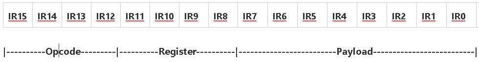
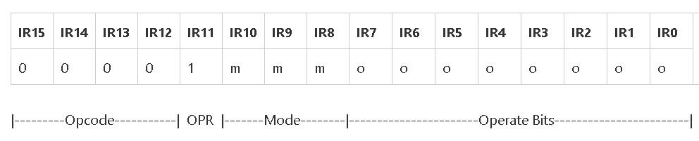
Suite-16 takes the basic PDP-8 concept, but extends it out to a 16-bit wide instruction. This means that you can have 16 instruction opcodes rather than 8, you can have a 4-bit field to define the register or the addressing mode - rather than 2 bits, and you can use the last 8 bits to address a 256 word page of memory or an 8-bit literal or index.
Additionally we are no longer working in Octal, the 4 bit wide bitfields lend themselves to being expressed as 4 Hexadecimal digits.
![]()
With 16 opcodes we can divide that into 8 memory access operations and 8 ALU operations.
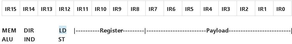
Memory Instructions
We can code into the memory access instructions a bit that determines if they are a Load or a Store operation and another bit that signals whether direct or indirect addressing mode is to be used.
![]()
ALU Instructions
With 8 opcodes dedicated to ALU operations we can have a more capable ALU and have logic instructions such as AND, OR, XOR, INV and dedicated instructions for ADD, SUB, INC and DEC.
Memory Addressing
Much of the flexibility of a particular instruction set comes from the various addressing modes that it can offer. Each new addressing mode adds further hardware complexity, and so it is often a compromise between flexibility and complexity.
The lower byte of the Instruction word IR7:0 - which is referred to as Payload in the diagram above, is a general purpose 8-bit bitfield that may be used for a variety of purposes. Following the instruction Fetch cycle, the instruction is latched into the instruction register and the Payload is also latched - so that it is available during the execute cycle.
One of the obvious uses of the Payload is to use it as a zero-page address in memory. The first 256 locations in RAM can be directly addressed using this 8-bit value.
Extending this concept a little further, if we fill in the register field, then one of the general purpose registers can be used to supply a further 16-bits of address - allowing a full 24-bits of addressing capability or 16M words of memory.
Group 0 Instructions
Currently in the Group 0 instructions, - those where the Opcode is 0, we have conditional branching instructions, Call and Return and 6 unassigned instructions. I had intended that some of these instructions would be able to access I/O and this is still current thinking, but through OPR there exists the possibility to manipulate the accumulator and other hardware directly.
Conditional Branching
First we have to look briefly at how Suite-16 handles conditional branching instructions.
![]()
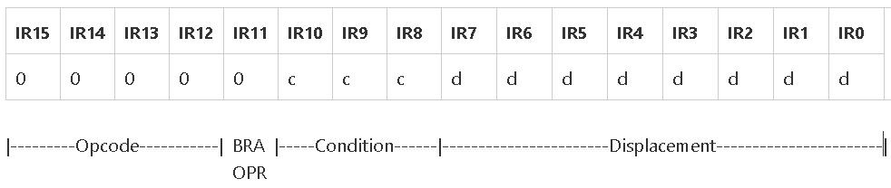
The diagram shows how we incorporate these into the Group 0 instructions. These do not have to address any of the general purpose registers - so the bitfield IR11:8 is available to use for other purposes.
With IR11 set to zero we indicate that the instruction will be a branch. Conveniently we can encode any of the 6 relevant branch conditions into IR10:IR8 including a BRA - Branch Always and a long jump, JMP which gets its target from the 16-bit word contained in the next instruction.
         00        JMP    16-bit                        Target = @(PC+1)
         01        BGT    AC>0                          Target = IR7:0
         02        BLT    AC<0                          Target = IR7:0
         03        BNE    AC!=0                         Target = IR7:0
         04        BEQ    AC=0                          Target = IR7:0
         05        BGE    AC>=0                         Target = IR7:0
         06        BLT    AC<=0                         Target = IR7:0
         07        BRA    Always                        Target = IR7:0
         08        CALL   16-bit                        Target = @(PC+1)
         09        RET    Return
CALL and RET instructions also fall into the Group 0 category. More on these later.
OPR Instructions
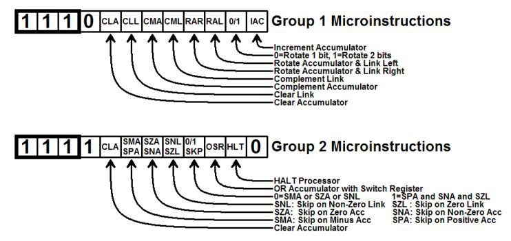
One of the most useful and powerful features of the PDP-8 instruction set was the use of OPR or "operate" instructions. At the time these were referred to as microcoded instructions - but not in today's use of the word.
![]()
The micro-instructions allowed direct control over the hardware, using the individual bits in the instruction to control the hardware. This is a powerful technique - and one that I'd like to incorporate into Suite-16.
![]()
If IR11 is set to 1, this signifies the Call, Return and OPR instructions.
-
Implementing the Hardware
10/17/2019 at 09:01 • 0 commentsWe now come to crunch-time. Having spent the best part of a week thinking about the Instruction Set and the Addressing Modes - I now have to review the wish-list and determine what can easily be implemented in readily available hardware. I need to make some hard choices of what is realistic and what will be left out for a later machine (possibly on a FPGA where resources are less limited). It's time to cut my coat according to my cloth.
This will mean examining every proposed instruction in detail and working out the data paths and internal cycles required just to make the instruction function. It's good that I only have 31 instructions to analyse and many of them fall into convenient groups.
Suite-16 already has some self-imposed limitations. The accumulator always forms one of the operands to the ALU. This makes it a whole lot simpler and you eliminate the need for a whole lot of data selectors connecting the register file to the ALU. Unlike an MSP430 where you can happily do an instruction like ADD R4,R5 our destination register is always the accumulator.
The register file I have selected has tri-state outputs, and this forms a natural data selector - during a register read cycle only the data from the register currently being addressed will appear on the register bus.
For direct addressing, the contents of the selected register is put onto the ALU bus. The register file already has internal address decoding, so the 4-bits needed to select the register can come directly from the bit-field in the instruction register.
For register indirect addressing we need to gate the register output bus across to an address register and gate the memory data bus across to the ALU bus.
Hardware limitations mean that there is currently no mechanism to transfer a memory read directly into a register. We need to load the accumulator from memory first and then store the accumulator to the register.
Arithmetic and Logic Instructions
These are probably the easiest to implement as they use only the accumulator AC and a designated register Rn as the operands. The result of the operation is deposited into the Accumulator
8n        AND       Rn     AND                AC = AC & Rn
9n        OR        Rn     OR                 AC = AC | Rn
An        ADD       Rn     ADD                AC = AC + Rn
Bn        SUB       Rn     SUB                AC = AC - Rn
Cn        CPR       Rn     Compare            AC = AC - Rn
Fn        XOR       Rn     XOR                AC = AC ^ Rn
It has been stated that the 16 registers are general purpose and R0 is the accumulator.
However, because of the nature of the accumulator, and its unique relationship to the ALU, and the desire to clear it, complement it, increment it or decrement it - it is probably best that it exists outside of the register file - i.e. as a separate register.
This means that opcodes 80, 90, A0 etc can detect the "0" and use the payload byte to form a zeropage memory address, and use a word from memory instead of using the Rn as the 2nd operand.
This access to zeropage memory could also be used for the direct addressing mode instructions:
 0n        ---       --
 1n        SET       Rn     Set Constant        Rn = @(PC+1)
 2n        LD        Rn     Load                AC = Rn
 3n        ST        Rn     Store               Rn = AC
It would be useful to be able to directly address zeropage memory - with the address contained in the instruction:-
20nn LD AC, (nn) or more simply LD @nn
30nn ST (nn), AC ST @nn
After an instruction has been fetched, and is latched into the Instruction Register, the PC can be tristated and the Address Bus can be driven from a Memory Address Register MAR. The MAR is responsible for putting the effective address onto the Address bus. This leads to the added complication of the Von Neumann model - where program and data are stored in a single, unified memory space, and the fetch and execute cycles have different addressing requirements to the memory.
Addressing Modes
Several of the addressing modes require the PC or a register to be modified by an index X. There are also the requirements of auto incrementing and auto decrementing of registers.
Fortunately when we are addressing memory, the ALU is generally not being used to operate directly on operands. We can use the ALU to calculate the new effective address by modifying the effective address by either adding a signed displacement to the selected register, or using the ALU to add 1 or subtract one from the selected register. It sounds simple - but will probably be challenging to implement in hardware.
Suite-16
Suite-16 is a 16-bit cpu built entirely from TTL. It is a personal exploration of how hardware and software interact.