 Vitaly
Finally, after waiting for new materials, checked some ideas and here are new details about MCH mounting.
New heroes :)
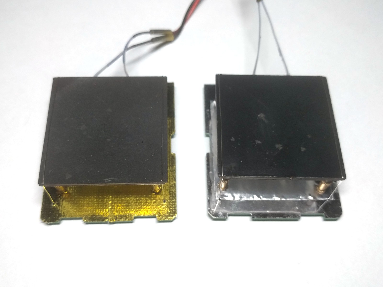
- black paint on top
- aluminium foil on bottom
- thermal reflective adhesive tape on PCB
Right is with:
- Panasonic PGS + black paint on top
- aluminium foil on bottom
- thermal reflective adhesive tape on PCB
Don't pay attetntion to dirty surfaces, that's after testing coverage quality.
Heater bottom side barrier
I wished to find better replacement for high temp silver paint. Classic solution to reduce IR emission is aluminium foil. So, needed to find suitable foil thickness (convenient to work with) and suitable glue (good at 300-400C).
First, any foil is ok to reduce (or reflect) IR emission. But too thick foil may be not convenient for mount. After search, i found nice foil in disposable aluminium baking forms :). It's ~ 60um thick (kitchen foil is 10-20um), cheap and easy to buy. The only advice i can give - select form with flat bottom.
Glue is a different story. There are only 2 types of accessible glues for desired temperature range:
- RTV-1 silicones. Gasket makers for auto can work up to 350-370C.
- Silica cements (exaust systems repair glue, for example).
Problem is, we need thick layer, and this glues dry not well without air. Also, cement is not convenient for work.
Since foil on MCH bottom does not need full surface bonding, we can use gasket maker. If we put small glue points on corners and between, that will be enough to hold foil well. And glue will dry completely in 1-2 days.
I selected copper-filled gasket maker, to use it again later as thermally conductive glue for RTD sensor.
How to bond:
- Put small glue points on corners and between.
- Cut foil peace with margin, place over and press with flat surface.
- Wait ~4 hours until silicone dries good enougth.
- Cut foil with sharp knife by heater perimeter.
- Need to wait 1-2 days more for full dry, but from this moment we can start paint heater top with black paint.
Heater top side cover
I had idea to use Panasonic PGS to equalize surface temperature. But, to be honest, amount of problems are not proportional to added value.
- Only pure PGS (without protection & adhesive layers) can operate at 400C.
- Cements do not hold PGS at all
- RTV-1 silicones can hold PGS but don't dry well at 50*50mm area in thin layer.
- PGS is very soft, and needs protection layer. Can be parcovered with paint, but that will not live too long.
Of cause, there are 2-component epoxies and thermally-cured 1-component glues, able to work at 300+ C. But those are not cheap, and not widely available.
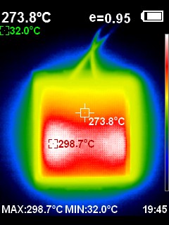
Here are 2 thermal images, as a result of experiments. Don't be too critical to temperature values - i used different paints and did not tuned camera.
Ordinary black top:
Top with PGS (poorly bonded with copper-filled silicone gasket maker):
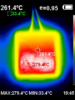
So, may be, PGS can help a bit, but it's not "magical" for this appliance.
My opinion is - use any black paint, able to work at 400C and more. Usually, all such paints have good adhesion to ceramic. So, select the cheapest one. Take care to manial, usually after dry, heating at 180C (or more) required for 1-2 hours. Since we paint heater - that's not a problem at all.
Useable heater area
As you can see on thermal images, ~15-20mm from power wires are not heated well. The rest is ok, if we do some discount for hobby use:
- Nobody uses lead-less paste for hobby.
- Even with 30C surface difference we have enough reserve if lead-less paste used (melt at ~180C).
I'd say, there will be ~30*45mm of "solderable space". Very nice.
Is it possible to do something better? Yes, of cause. But advantage of this device is to be small and easy to do, good for rare use. Such simplicity compensates it's disadvantages for many cases. If you need something better - use microwave ovens, bga reball stations and so on. Segment of bigger devices is already well-covered.
PCB reflective layer & mounting
PCB cover is not principal, because almost everything is already dimmed by heater's foil. Use any reflective adhesive tape, suitable for termal insulation - pure aluminium, or something reinforced.
As you can see on first image, left unit uses reinforced gold foil tape for auto, right unit uses ordinary aluminium tape. No principal difference.
Here is is PCB bottom view from thermal camera:
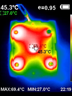
As you can see, most of heat goes via metal mounts. Most depends on contact between DIN914 screws and brass inserts. When top screw are inside inserts less than 2.0-2.5mm, result is good.
Currently, when used 10mm length inserts and 10mm screws, air gap is 17-18mm air gap. Not too bad, but i would try to reduce. Also, switch from M3 to M2 screws can improve situation a bit.
Summary, and what's next
- After experiments, fount optimal combination of materials - accessible, cheap and easy to work with.
- Ordered M2 screws and inserts of different length, to try reduced air gap.
So, i hope next iteration become be final.
Discussions
Become a Hackaday.io Member
Create an account to leave a comment. Already have an account? Log In.