Valentin
-
Further Development
03/27/2021 at 21:12 • 0 commentsAlthough I haven't been posting updates here lately, that does not mean that I was inactive. Since the last project log, a lot of improvements landed:
- A new hardware revision (V5) that adds connectors for additional display types, LiPo battery charging and very low deep sleep current.
- The driver library can now use the vendor wavefrom files (.wbf waveforms). Unfortunately, these are not easy to find, but some are scattered around the web. It would be nice to analyze them and build our own waveform files one day, which can be freely distributed.
- The board can now be programmed with the Arduino IDE.
- An improved API and other minor changes.
So, If you want to keep up with the development of this project, I suggest to keep an eye on the GitHub repository. Or even better yet: Join or Matrix / Slack channels where we discuss further development, show projects and exchange ideas.
![]()
-
A New Revision
10/29/2020 at 11:59 • 0 commentsFirst, let me say thank you for all the contributions and suggestions which where contributed to the project GitHub Repository. It is great to see that this project sparks your interest and to learn about ways to improve it even further!
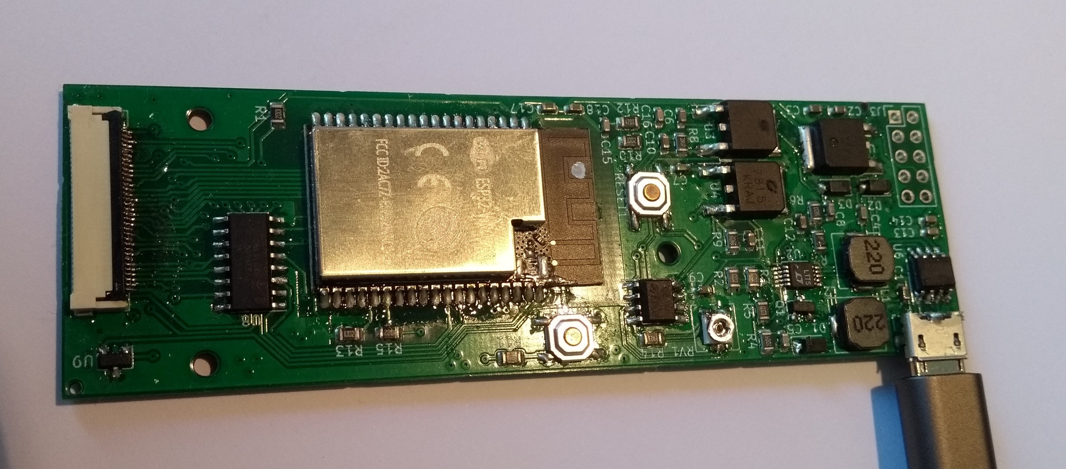
Based on this, a new revision of the board where developed (Actually there where two "Revisions" since the last project log, so this latest one is called "V4"). The main focus here was to be more power-efficient to enable battery-powered applications. To achieve that, two LT1945 converters are used to derive the necessary voltages instead of using additional linear regulators. This comes at the cost of more parts overall, however, the LT1945 chips are available cheaply from AliExpress and most additional parts are basic parts which should be available at many chap SMT assembly services. Additionally, a less power-hungry LDO is used to power the ESP32.
So overall, the improvements over revision V2 include:
- Deep sleep current of ~80uA if powered with 3.7V and the display attached. If the display is attached, deep sleep current rises to ~440uA and I am not quite sure why, yet. Any suggestions are welcome :)
If powered via 5V, unfortunately the p-channel mosfet which is used to gate the booster power might still turn on, which increases sleep current to ~340uA without display. This could be fixed in a future revision, but for most battery powered applications a lower voltage is used anyway.
- Slightly faster drawing (-80ms for a full 16bpp frame, -100ms for a clear cycle) at the expense of one broken-out output pin.
The PCB and updated firmware library are now available on GitHub!
- Deep sleep current of ~80uA if powered with 3.7V and the display attached. If the display is attached, deep sleep current rises to ~440uA and I am not quite sure why, yet. Any suggestions are welcome :)
-
Bigger is better?
07/17/2020 at 21:24 • 2 comments![]()
When it comes to E-Ink screens, bigger is better, right? One of the goals of this project was to be able to step up from the 6" screens of previous designs to 9.7" Kindle screens. But why stop there?
E-Ink makes even larger screens, with the next size being 13.3" panels. So compared to 9.7" panels, they have about double the surface area and are roughly A4-sized. These would be very nice for E-Paper dashboards and the like. I also want to build a portable E-Ink terminal, so this would be perfect, right? Well, it depends. But I'll go into that later.
First: How do you get such a thing? This was actually quite difficult. Yes, E-Ink offers these Modules on their Website as samples, but 500$ was just not worth it for me. When you request quotes from some big suppliers, they usually ask how many thousand pieces you want.
But then, I stumbled upon a listing for a 13.3" E-Ink screen on AliExpress, with the model number PENG133D. Of course, there is absolutely no information available under that name, but the picture looked awfully like the E-Ink ED133UT2. Additionally, since E-Ink still holds some Patents and is afaik the only manufacturer currently capable of producing these screens, there is not much else it could be. So, a friend and I decided to spend the 200$ on an experiment. Still not cheap, but this is probably as cheap as these screens go, considering they are not mass-produced in an order of magnitude the Kindle screens are.
When I received the display, aside from the label, it seemed to be indistinguishable from the ED133UT2. It features the same connector as the 6" screens, however some pins are wired differently, so just connecting it directly to the V2 board will create a short through the display! So, I had to design an adapter board first, which is then bridged to the control board. If the setup in the picture looks hacky, that's because it is:
The current revision of my adapter board has the connector facing the wrong way, requiring the cable to be connected to the rotated adapter board. Furthermore, 33pin FFC cables are not available at any local electronics shop, so I used a cable from an old laptop and cut it down to 33 pins. Then, just to be sure, I hacked my prototype board to use 5V for the boost converter (In the current gerbers, there is a jumper for that).
Adapting the firmware to get a first picture was actually quite simple, though I have not yet calibrated the grayscale timings.
But: Is it worth it?Well, it depends. 200$ is a lot of money for a screen. Well, compared to a Dasung Paperlike E-Ink monitor which uses the same screen and costs 1000$, this is way better, but nevertheless. And for that price, it suffers from some problems:
- It's on a glass substrate. So if you want to build a mobile application,
you'll need a tough case to support that thin, A4-sized glass panel. - It has a glossy surface finish, somewhat invalidating the sunlight-readability we expect from E-Ink.
- Those flimsy flex PCBs have to be mounted somehow.
There actually is a version on Plastic substrate and with anti-glare surface finish, the ES133UT2. If someone knows a reasonable way to get by these, please let me know :)
Firmware support and the KiCad project for the adapter will be published after some more fixing and testing.
- It's on a glass substrate. So if you want to build a mobile application,
-
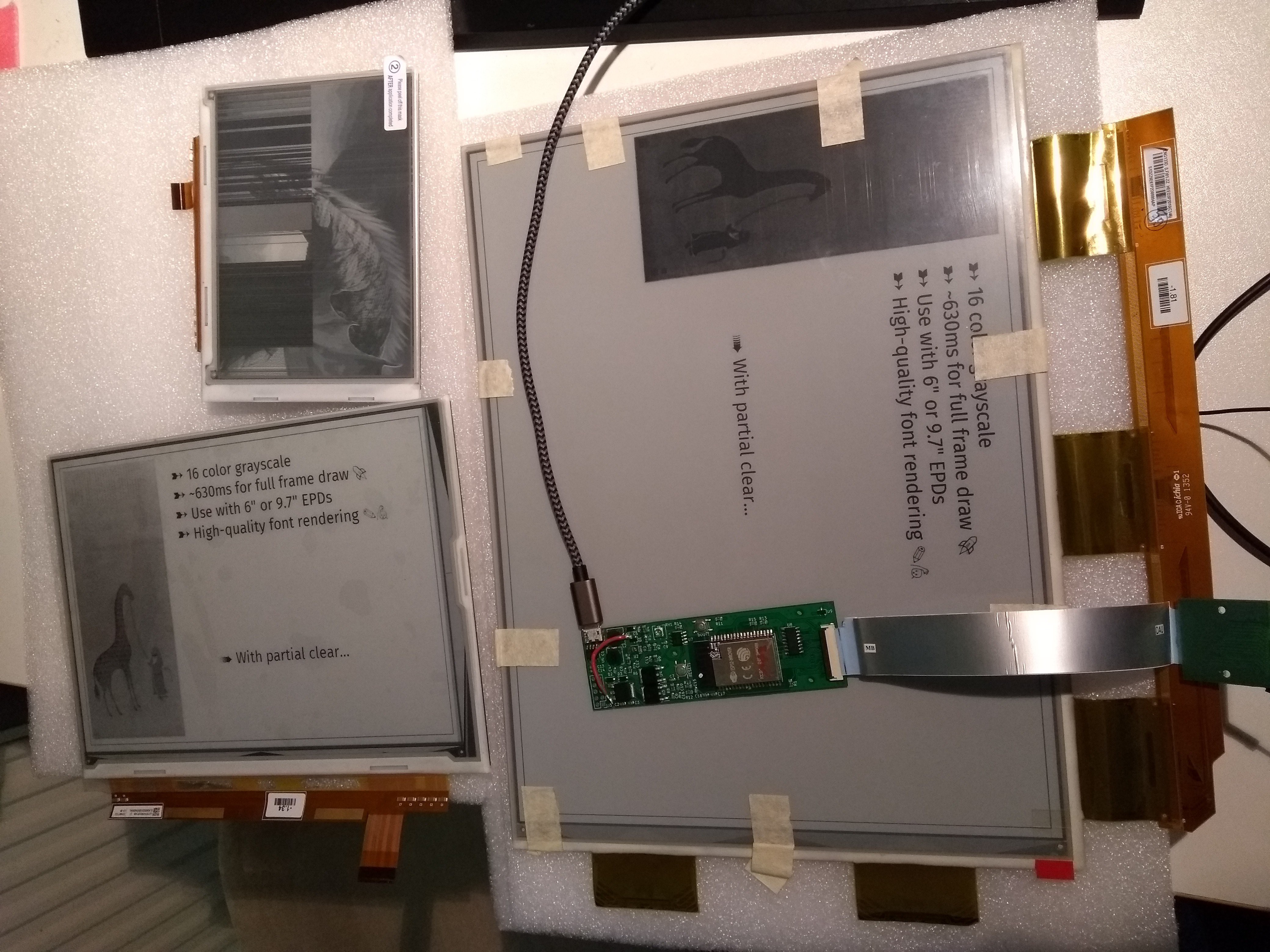
Terminal Example and other Improvements
06/02/2020 at 18:19 • 5 commentsDuring the last weeks, various improvements to the software and hardware where made, in part thanks to contributions from the Hackaday community. The highlights include:
- Further drawing speed improvements: A full screen draw is now just under 500ms, partial draws can be much faster!
- @Sebastius made the PCB more robust and versatile by adding the option to run the power supply on 5V or 3.3V via a jumper, adding a test pad for VCOM and improving the ground plane connections.
- Fonts can now be rendered in any (4 bit grayscale) color and can be drawn on a background. This was essential for the terminal example.
The Terminal Example:
What you see here is a (almost) complete terminal (actually a port of the simple terminal from suckless.org), running on the ESP32! Currently, I'm using it to mirror a terminal emulator through `script -f /dev/ttyUSB0`, but I'm working on hooking up a laptop keyboard to make it fully stand-alone!
-
Software at last...
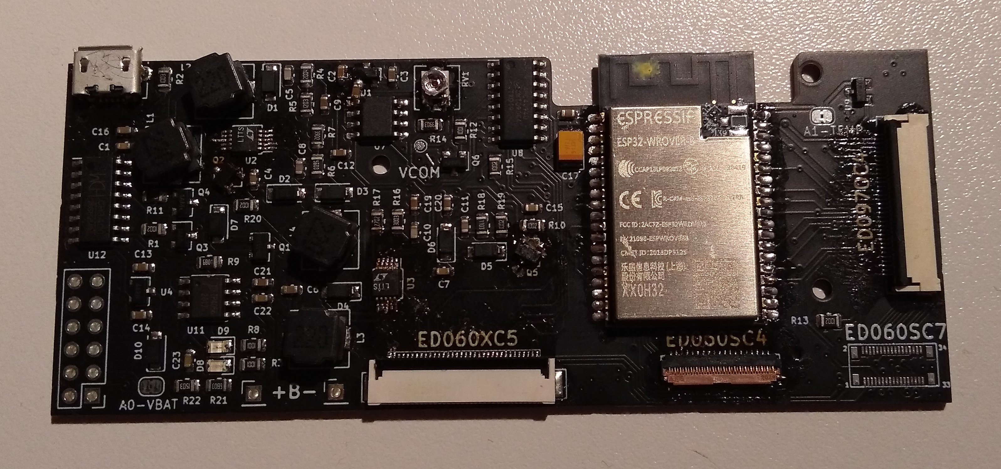
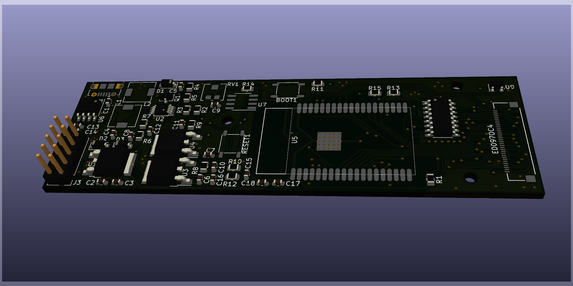
04/22/2020 at 12:08 • 0 commentsNow that my v2 PCBs have arrived and I have assembled a test board, it turns out most of the work is actually software. But first: This is how the new version looks like:
![]()
![]()
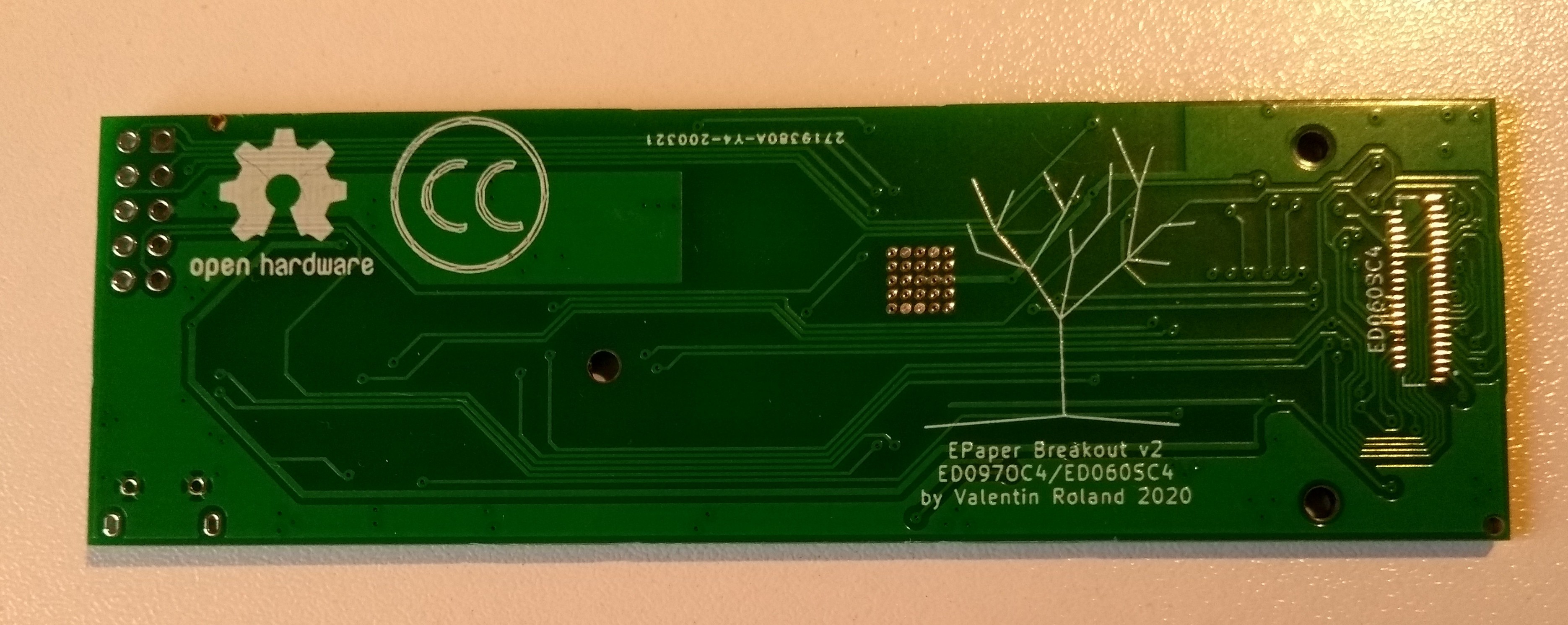
As you can see, the new version is much more compact. Additionally, there is now one component on the back side: The connector for the ED060SC4 is optional, to be populated if needed. Currently there is no software support for it, but I'll fix that in the following days.
Actually, writing the software driver is taking a lot more time than I anticipated. Part really was just experimenting, figuring out the functional details of the ePaper screen and familiarizing with the ESP32.
Another one was rewriting all my display routines to use buffers with 4bit per pixel (instead of 8), for better memory efficiency and faster display (which is still somewhat bound by memory speed).But I also wanted to make sure the board is actually usable by others, which is why I am currently working on re-structuring and documenting the driver. You can get a preview of the displays' capabilities here: https://epdiy.readthedocs.io/en/latest/api.html Or watch the updated demo video :)
-
v2 underway!
03/21/2020 at 10:31 • 1 comment![]()
Over the past few days, I've been working on a revised PCB. It is now in production, so given international shipping will continue in the following weeks I'll soon be able to test it!
The following improvements over the original version where made:- Switched to the ESP32-Wrover Module, which features 8MB PSRAM. This allows to hold full frame buffers in memory.
- A footprint for an optional connector for the ED060SC4 6" E-Paper display was added. This should allow for driving either a 9.7" or 6" display with the same board!
- As some ESP pins are now needed for the PSRAM module, some configuration pins where moved to a shift register.
- A temperature sensor was added to be able to (in theory) adjust the driving waveform to the environmental temperature.
- Smaller PCB outline of ~100mm x 32mm.
- The board can be powered directly through 3.3V (without USB) for lower power consumption.
- Instead of I2C, a full SPI port is broken out.
Meanwhile, there are still some things to improve software-side: Currently, the refresh time of about 1100ms is mainly bounded by the ESPs flash bandwidth. With better data encoding / compression, it could be lowered even further.
-
Font Rendering and Partial Drawing
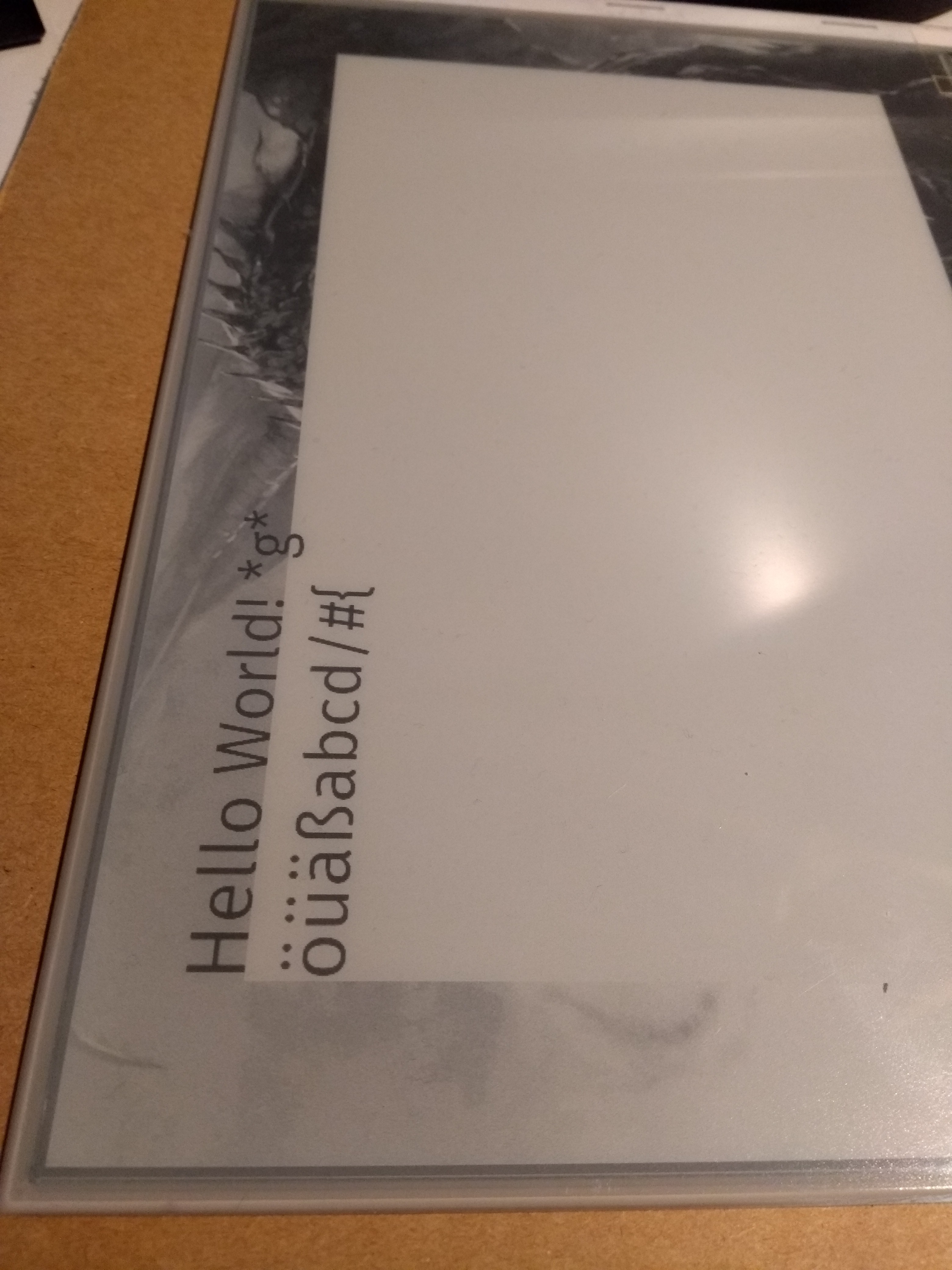
11/18/2019 at 21:44 • 0 comments![]()
Now, finally I implemented what these displays where originally designed for: displaying text. Unfortunately, the ESP32 does not have enough RAM for a real frame buffer (maybe a version 2 will use a module with PSRAM). So, I have to resort to partial refresh / drawing.
For the image shown above, I first displayed a full-screen grayscale image as usual. Then, I cleared the middle area and proceeded to draw the text line-by-line. If you screen content does not need to be updated often, this should suffice. Otherwise, you can always stream frames via wifi.For my tests I used the latin1 character set and the Fira Sans font, however, this is completely customizable.
-
ESP32 timing
11/01/2019 at 11:32 • 0 commentsHello World! Finally, the project is ready to go public. If you have any ideas, improvements or comments to share, feel free!
During the last days, I struggled a bit with getting the timing for the gray scale output right. Each row has to be activated for a only a few microseconds to only dim it slightly. While this worked most of the time, sometimes, the code took much longer, resulting in dark horizontal stripes. Debugging this was quite a journey, since I was new to the ESP32:
- Coming from the world of Arduino, having a real-time OS running on the chip was new. Disabling interrupts during the critical sections helped, the fact that the noInterrupts() function of the Arduino framework for the ESP32 is just a dummy did not.
- At this point, most bad stipes where gone, but timing was still somewhat irregular, even when using the hardware timer. I thought using hardware timer interrupts is as good as it gets when trying to do exact timing, but apparently I was wrong. If someone has an idea why this could be, please tell me!
- Finally, tagging the critical function with IRAM_ATTR and busy waiting for a set number of CPU cycles did the trick.
Busy waiting does not seem like the most elegant solution, but it works. Refresh times are now at about 2 seconds for a gull grayscale image of 1200x825 pixels. If I could manage to already shift in new data while waiting for the current row to fade, this could be even faster. I'll have to try some things :)
EPDiy: 9.7"/6" E-Paper controller
I always wanted a large, affordable E-Ink screen to play around with. This board talks to cheap E-Reader replacement screens with an ESP32.