Matthew James Bellafaire
-
BLE is Here!!!!
07/14/2020 at 02:54 • 0 commentsSince the last update not a lot has gotten done. That isn’t to say there’s been no work happening on the project, just that the progress has been slow and tedious almost every step of the way. I recently upgraded my phone to the OnePlus 8 running android 10 which resulted in my companion app all but breaking completely. In some cases, it would work alright, when the app was open in the background and I was actively using my phone the smartwatch would sometimes grab the notifications over Bluetooth serial. On my previous phone (a Galaxy Note 5) the app just needed to open a thread that attempted to connect to the device occasionally and that worked well enough for a while. I’ve been wanting to change the way the app works for awhile but getting my newer phone kind of forced my hand.
Now that I’m running Android 10 there’s been no real way to get around it. BLE is the way to go with a project such as this, while Bluetooth serial has some definite benefits in ease-of-use, the pairing time takes too long to be practical. The biggest problem I’ve experienced with BLE in the past is the lack of good documentation. Luckily this time around I stumbled across two incredible resources for creating a BLE GATT Server in the form of straight forward examples (https://stackoverflow.com/questions/37181843/android-using-bluetoothgattserver and https://riptutorial.com/android/example/30768/using-a-gatt-server). Both examples allowed me to get some code running and configure a GATT server to present data to the ESP32 Smartwatch.
Now for anyone interested in the code here’s a quick overview of how all the major functions work along with a flow chart. If you’re interested in creating something similar or adapting the code yourself, I hope this helps. If you’re not really interested in the code, then just skip to the last paragraph.
![]()
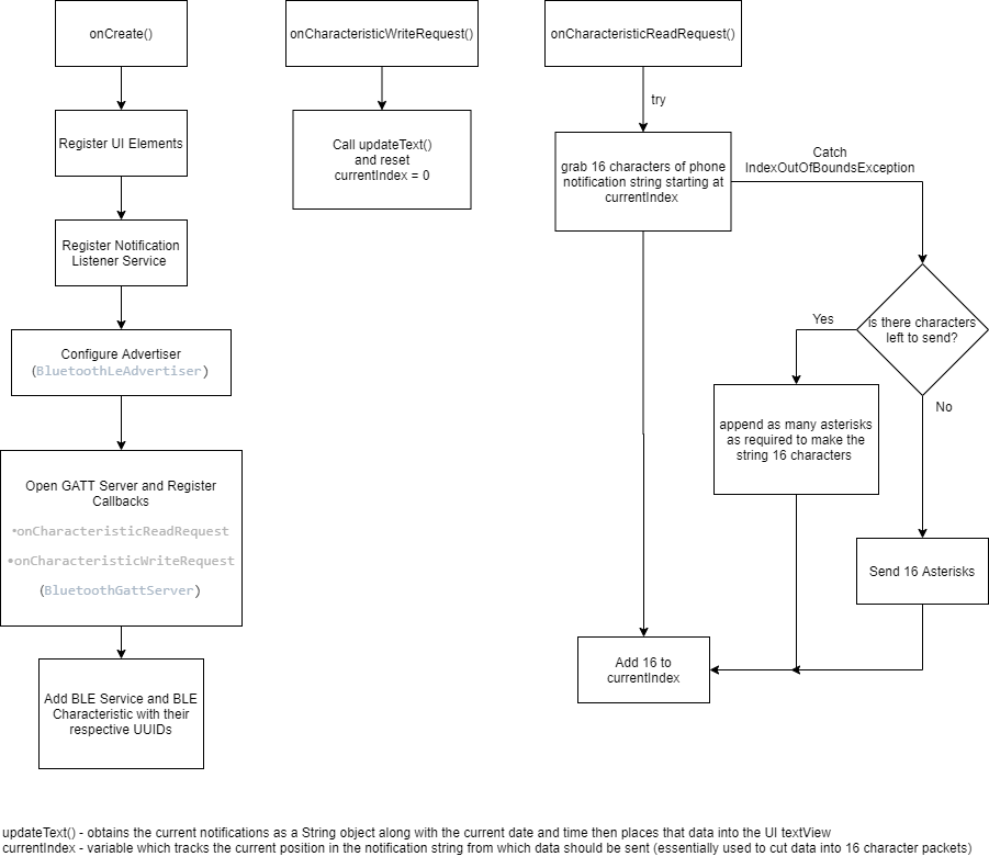
The above diagram starts from the onCreate() method which initializes all the required elements in the code. UI elements and the notification listener service used to read the notification-bar notifications are registered (notification listener is also registered in the manifest). Next the BLE server needs to be configured, first we set up the advertiser then we open the GATT server and register the required callbacks. Almost all of the useful functionality in this app comes from the two callbacks registered in the onCreate() method. Finally, we add the BLE Service and the BLE characteristics, both have their own UUID hardcoded into MainActivity.java.
The callbacks used by the GATT server are shown in the diagram. Since we don’t know when the watch will connect using these callbacks allows for the watch to initiate a connection, give commands, and receive the data it needs. For the moment the only data requested by the watch is the notification data but by adding more characteristics or commands the watch could read anything forwarded through the app. When the smartwatch connects the first thing it does is write to the available characteristic which triggers the onCharacteristicWriteRequest() (let’s say CWR from here on out) callback. When CWR is called it triggers it first obtains a new String to represent the notifications of the android device including the current date and time (I plan to use that information later). The next thing the CWR does is reset the currentIndex variable which I used to cut the notification string down into 16-character long packets to be sent over Bluetooth.
After sending a write request the smartwatch then needs to trigger the onCharacteristicReadRequest() (CRR) callback. Essentially all this callback does is reply to the read request with a 16-character string which is a part of the larger notification string. Every read will yield a different substring of the notification data which can be concatenated back together on the smartwatch’s end of things. The end of the notification data is indicated by 3 asterisks (*), but to keep things simple data packets stay as 16 characters and any empty space is filled by asterisks. The smartwatch will stop reading the data from the GATT server as soon as it detects that the string ends with “***”.
Changing over to BLE should increase the battery performance of the watch and the companion smart phone. I’m sure in the next few days I’ll find a few issues with the BLE implementation here but for the most part I expect that the code will function as shown above for quite a while. This project has been challenging every step of the way and I’m glad that it’s all coming together as well as it is. Either way thanks for reading, see you in the next log!
-
Firmware/Software update
07/01/2020 at 03:29 • 0 commentsIn the last log the watch had only basic watch functionality and couldn’t do much outside of telling the time and reading its own battery state. In the last few weeks the functionality has grown to encompass more of what would be expected from a basic smart watch.
Most of the time I’ve spent on this project in the last two weeks has been focused on getting an android app to work with the watch. Until now I’ve never written an android app, although I have a lot of java experience, I found android to be much more of a beast than originally expected. Most of the code that’s used in this project comes from open-source projects or stack overflow posts. Data is communicated between the watch and my phone over a standard Bluetooth serial connection using a library by harry1453 (https://github.com/harry1453/android-bluetooth-serial) which massively simplifies the Bluetooth code. In order to actually get the notifications themselves I modified an example by kpbird which can be found at: https://github.com/kpbird/NotificationListenerService-Example/.
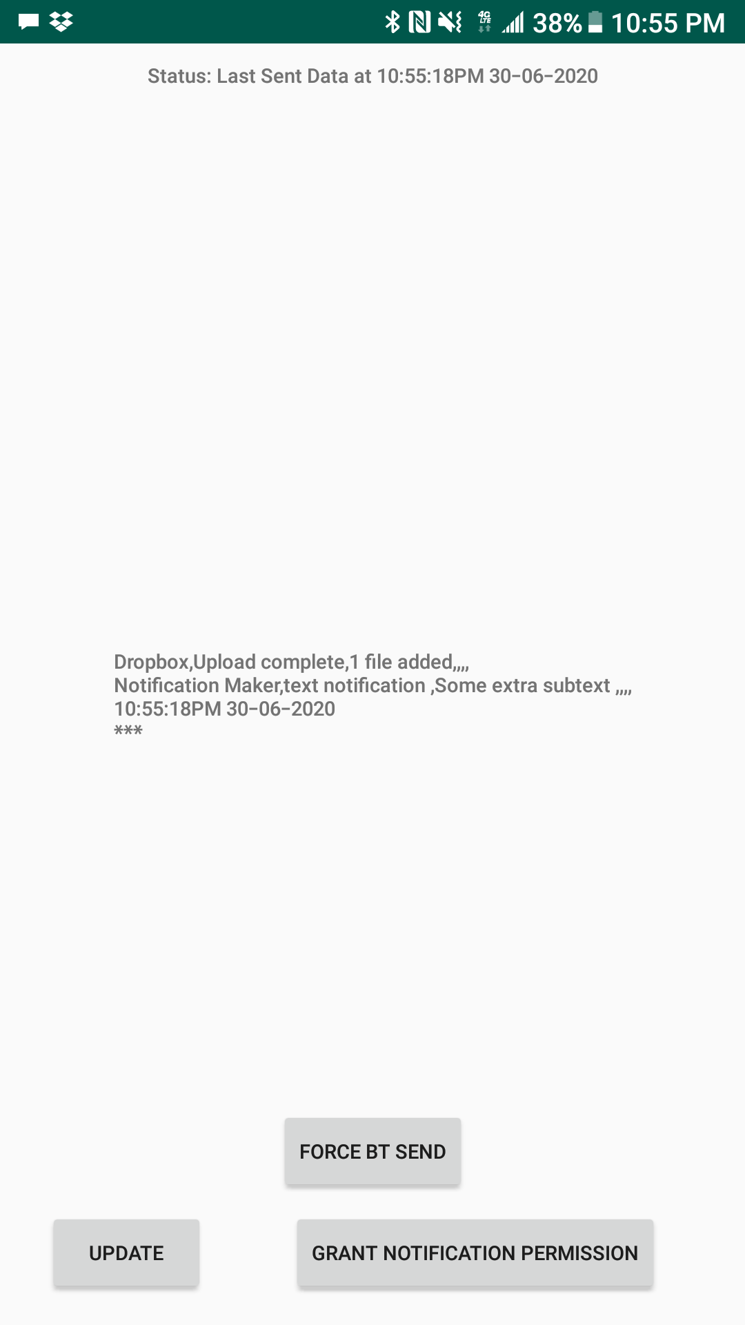
I ended up writing the app twice just to clean up the code once I had something that kind of worked. For all the effort the app in all its glory looks like:
![]()
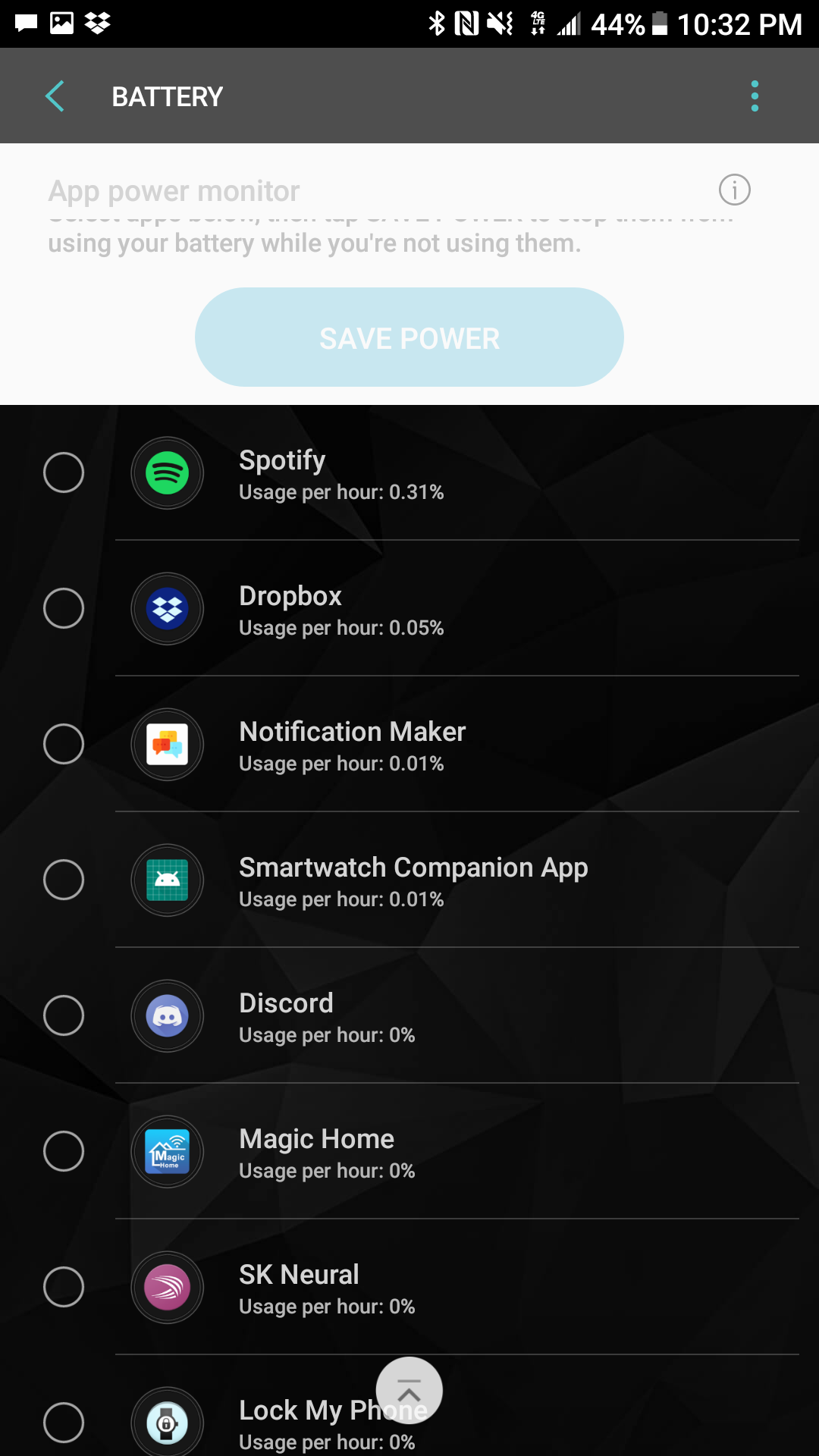
The app attempts to send data to the ESP32 smartwatch about every 15 seconds over a standard bluetooth serial connection. When it connects it sends across the string that is shown in the middle of the app window. Using this approach is less than ideal but in practice it’s not too bad. Even though the app runs constantly in the background and is constantly trying to send data it appears to only have a negligable power useage according to my phone’s battery monitor. With all that said I’m still planning to rewrite the app to operate more efficently or switch to BLE. I’m open to suggestions on how to use the bluetooth functionality here, I’m new to android and there’s a lot that I still don’t know about.
![]()
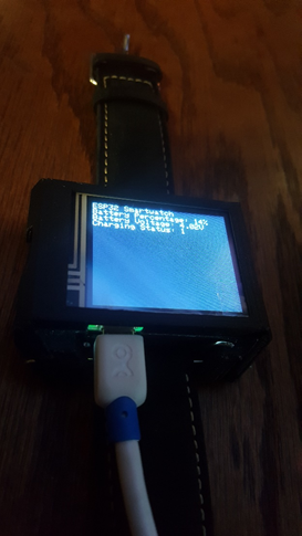
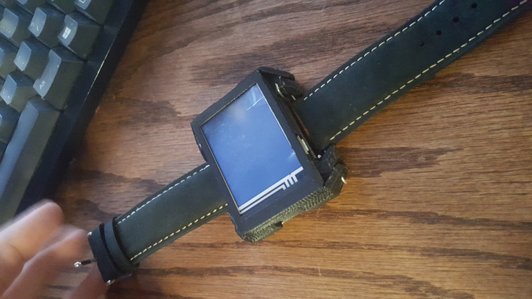
With the app out of the way lets move onto the updates to the firmware that have been made recently. A major improvement to the watch was a software switch away from drawing individual pixels on the screen directly. I stumbled across the GFXcanvas16 class in the adafruit GFX library (this is the only real documentation I can find on it http://adafruit.github.io/Adafruit-GFX-Library/html/class_g_f_xcanvas16.html). Using the GFXcanvas16 the code can now buffer the image before displaying anything, this cleaned up some flickering that would occur from updating and allowed me to make the UI a bit more lively. Notifications received by the watch are partially displayed on the home screen (app name only) and in the notification menu accessible by the bell icon. The notification window allows all the received data to be viewed in one place for any notification. I put together another short video demonstration of the watch in operation, a picture’s worth a thousand words so here’s 30,000 words per second.
Under the hood the watch opens its Bluetooth serial port every 120 seconds of deep sleep and waits for a connection for a maximum of 10 seconds, when the notifications are received the string is stashed in the RTC ram and the esp32 goes back to sleep. So far this approach doesn’t seem to cause a significant power drain on the watch (maybe 15% every 8 hours?). I haven’t yet been able to give the battery a proper test since I’ve written code to the watch almost everyday giving it time to charge up.
With all that said the project is coming along nicely and I hope to see you in the next log!
-
Running Some Basic Code On The Watch
06/15/2020 at 23:26 • 0 commentsI've been working on this project non-stop since I assembled the board yesterday. The fix for the battery monitor I talked about in the previous log seems to have solved the issue of charging not being detected. I've also managed to bring over a majority of the code from the Revision 3 watch to use as a starting point.
Either way, I figure since I've never shown a demonstration of the watch actually working on this project page now's as good a time as any. The code running at the moment can only really handle basic tasks like reading the battery and navigating some menus but it's promising for the future of the project.
See you in the next log! -
Revision 4.1 Works!
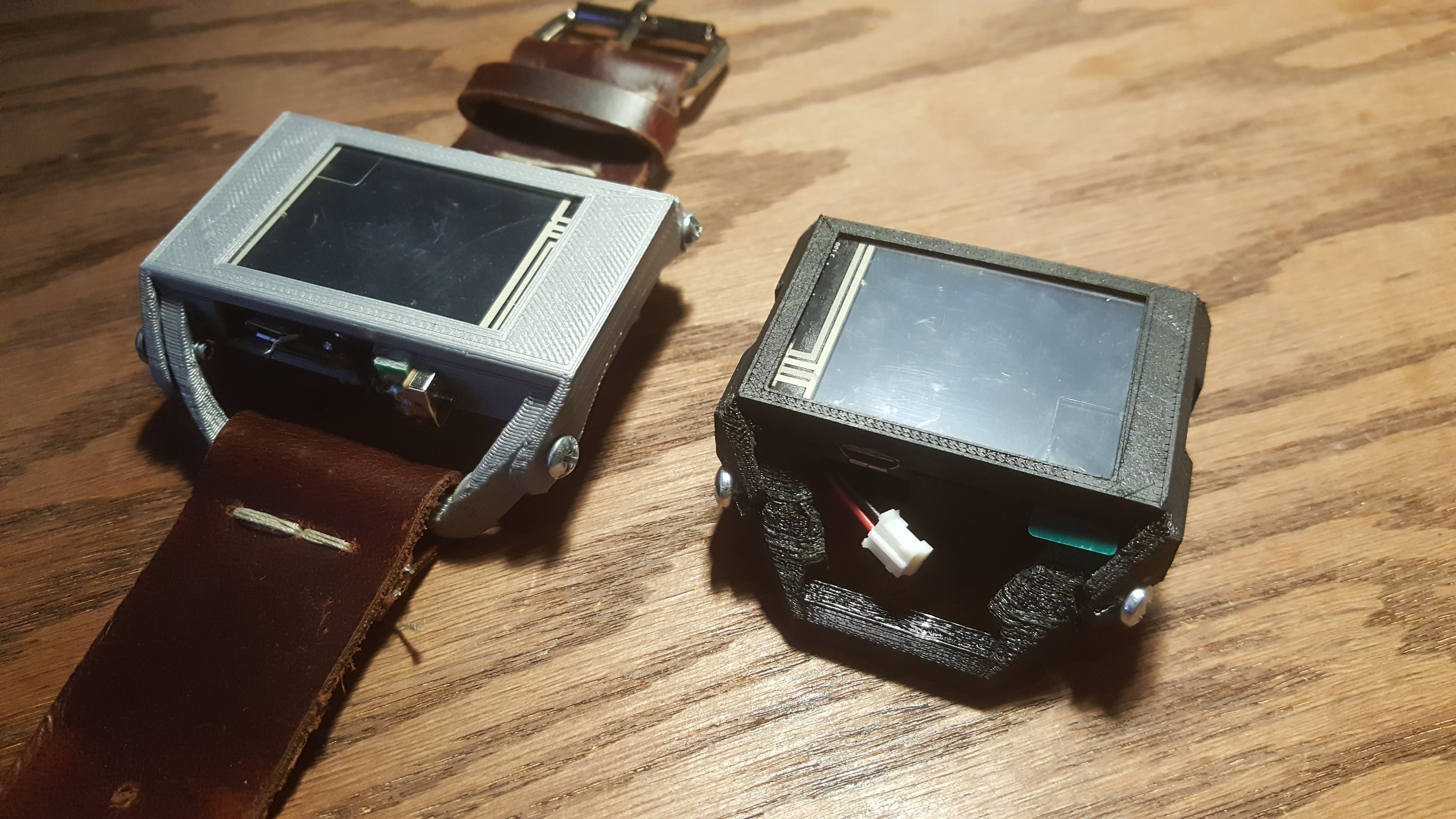
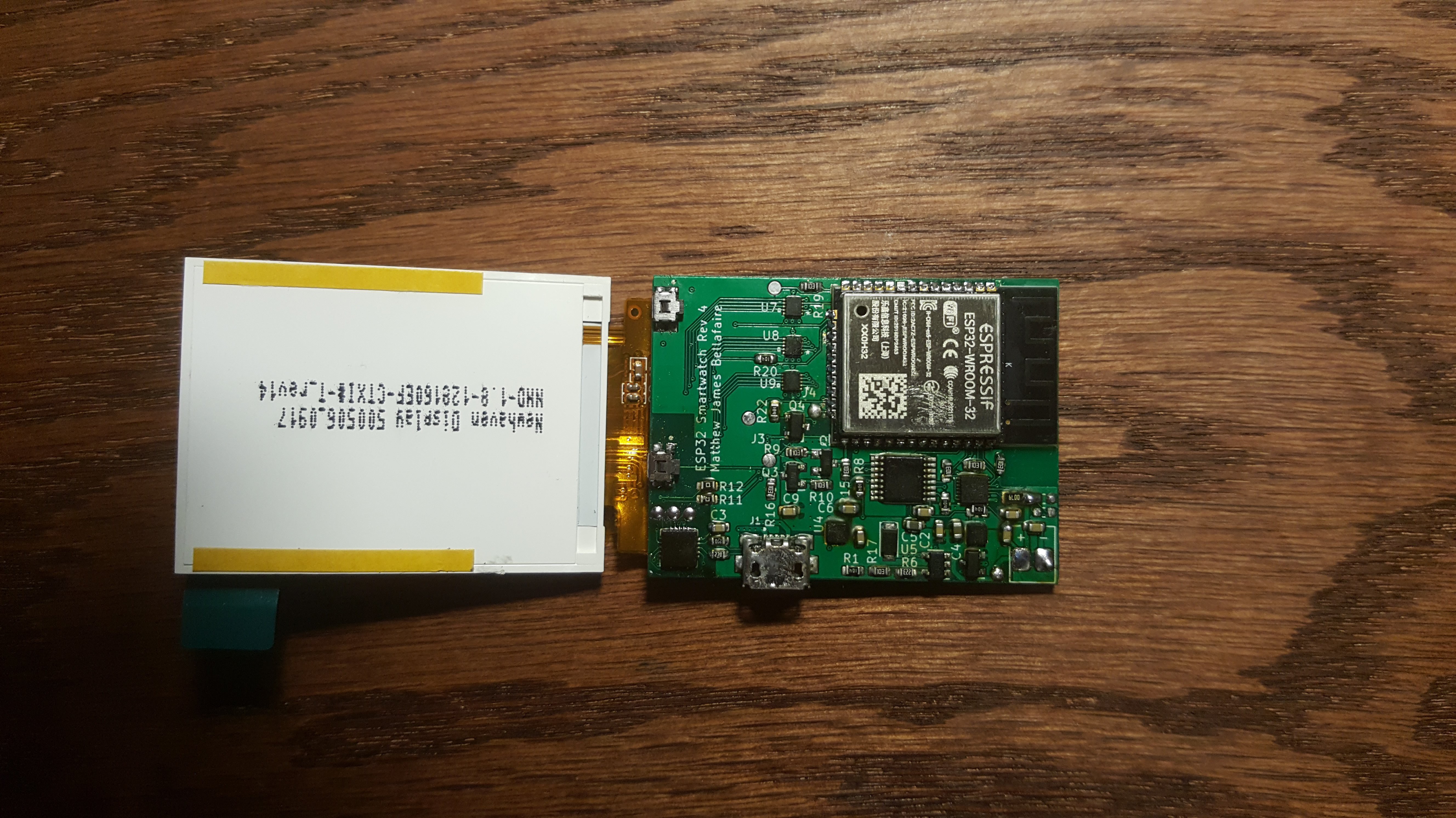
06/15/2020 at 02:41 • 0 commentsThe revision 4.1 boards have arrived today, and the new watch has been assembled. I’m happy to say that this revision works! So far only a small portion of the code has been implemented to just test the components onboard but for the moment everything seems to be working!
There were some difficulties in assembling the board. Two boards were assembled, the first one had a defect that I couldn’t exactly track down, on my first assembly attempt I found that there was something shorting the EN pin to ground, this prevented the ESP32 from booting up. I removed all components attached to the EN pin and found a 30 ohm short to ground and there was nothing visible causing the problem (I can only assume there was some defect causing a via to connect to ground but couldn’t find exactly where that short was happening). After an hour or two of trying to fix that issue I cut my losses and just assembled a second board which is running the watch in the above image.
Currently the code I have running simply boots up the display and shows some of the readouts from the battery monitor IC (MAX17260) then puts the device to sleep. For the moment everything seems to be working, the ESP32 can communicate with the two I2C devices on board (battery monitor and touch controller) and best of all the LCD works!
With all that said I’ve found a small error in this version that I’ll have to fix. Currently the battery monitor can’t see the charge current since the charging IC connects directly to the battery without going through the sense resistor. This causes the battery monitor to not see the device as charging, the result is that the battery percentage doesn’t increase when charging.
I’ve also made some modifications to the case design. The case is no longer held together by screws, instead the strap holder was created from some pieces of 24-gauge steel wire. The advantage to this design is that the watch can use any 24mm (or smaller) watch strap bought online. This solution makes the watch easy to assemble and disassemble with just a pair of pliers and strengthens the overall watch body.
Overall the project is on the right track now, and this revision of the board will work perfectly for developing software. I’m still planning on doing a revision 5 which will just be a pass on the layout to compact the design as much as possible.
See you in the next log!
-
Here we go again!
06/07/2020 at 20:18 • 0 commentsIt’s been awhile since I’ve updated the log for this project. A lot of work has happened on this project since the last update. I’ve assembled the V4 smartwatch and attempted to get it almost working. All the peripheral devices work well battery management and charging are leagues above the previous revision and work great. This project has taught me a lot about design, and although there have been more setbacks then I can count I’m still determined to finish this project and have a smartwatch with everything that I want a smartwatch to be.
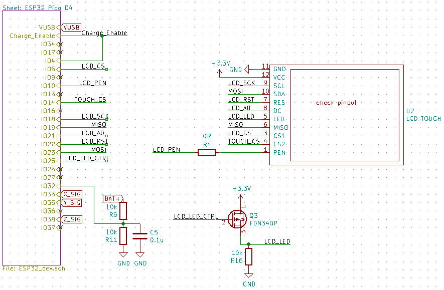
With that said it looks like Rev 4 is a partial failure due to the LCD display used for the project. Regardless of what I tried I could not get the smartwatch LCD to work so it’s time to spin another board. If I had a logic analyzer handy, I’d be able to tell with more certainty, but all signs point to the level shifters used to by the display failing to transmit data to the display. I’ve made a few minor edits to the display and decided to go with the same module used in Revisions 1-3, by some miracle I managed to track down the actual LCD module (with no adapter board) on AliExpress (https://www.aliexpress.com/item/32840333697.html?spm=a2g0s.9042311.0.0.529d4c4dVe76Mt) which I’m more than happy to use since it doesn’t cost me an extra couple of millimeters of thickness. I’ve ordered 5 of them since they’re so cheap (and because I was stuck paying $20 shipping anyway) so now I just wait for them to arrive. In the meantime, the electrical schematic has been changed to use this LCD once again following the working parts of the Rev 3 schematic. Using the available libraries for the ST7735 will make the software much easier to write although I do plan to buffer the display for better performance.
For the most part the next revision (revision 4.1) doesn’t change too much from the previous version, the LCD has been swapped out and there were a few minor edits to connections that I had to bodge in the assembly of rev 4 so lets talk about the newer changes then what works with Rev 4. First things first the LCD:
Changing to the old LCD (ZJY117) opens some pins on the board. I still plan to do a revision 5 where the board gets compacted to fit a wearable formfactor but for now making these edits involved a minimum of layout changes on the PCB side. The LCD itself communicates over SPI with a few extra pins. To save power I have two options for powering the LCD backlight, the primary goal is to have the LCD backlight powered by its own LDO along with the rest of the LCD this way I can ensure that no power is sent to the LCD when not in operation since in previous revisions the LCD drew too much current in standby and resulted in a significant drain to battery life. The LED will be switched by the 2K7002K or by simply applying power to the LDO used by the LCD. I’m not sure yet which of these I’m going to use yet so when I get the newer board, I can select by adding the jumper or the FET.
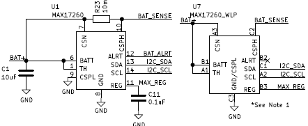
Another problem is that I cannot source the MAX17260 in it’s TDFN package easily from digikey or mouser unless I want to buy 490 of them and wait 3 months. I have a few of the TDFN versions laying around but just to be safe I’ve added the WLP package to be left un-populated if there is no choice and the WLP is the only available IC. This is just to be on the safe side, however using the WLP comes with a price, the ALRT pin cannot be accessed due to the allowed trace size of the PCB so switching to the WLP package does come at something of a price.
For power the design uses two 3.3V regulators which allows me to completely shut down the LCD in software to prevent power drain when not in use. The new LDO takes the place of the previous 2.8V regulator used for the previous LCD.
Since we have extra pins now, I also brought back the accelerometer as an optional addition to the board if everything goes well. In the future this could add additional functionality and another means of waking the device up if desired.
Now onto the positive note of the log, what works.
The new battery management system works much better than the previous version, since everything can be controlled from the software of the ESP32 there’s a lot more flexibility in managing the battery. In previous revisions the battery was automatically disconnected whenever voltage fell below (or went above) a set threshold, this resulted in the device going into complete shutdown without any way to recover. This was an issue because the constant voltage phase of the charging IC would cause the device to shut down until the device had drained enough to re-enable itself.
The newer version also corrected an on-going issue where plugging the device in to charge would interfere with USB communication and result in difficulties uploading code to the watch unless the battery had just the right charge. USB communication in rev 4 works flawlessly and did not require any changes on the new board.
The MAX17260 battery monitor is my favorite feature of the Rev 4 board and allows for easy battery monitoring. To test the performance I created some test code which allows the ESP32 to transmit the battery monitor data directly to a webpage (although most of the credit goes here https://circuits4you.com/2018/11/20/web-server-on-esp32-how-to-update-and-display-sensor-values/ I just modified the code to my purposes). Using this I was able to watch the raw data of the battery monitor as the battery discharged without any connection to my PC. The output webpage looks like this:
Configuring the MAX17260 to work properly wasn’t exactly an easy process but maxim had some useful documentation and startup code to get things started although it wound up being more of an ordeal than expected. Now the code works so I can slot it into the newer smartwatch without too much fuss.
The project is on the right track now and I look forward to testing the Rev 4.1 board. This smartwatch project has been much more difficult than I originally thought when I set out to create my own smartwatch but I’m learning more and more along the way and that’s really the goal of everything I try to do here on my Hackaday.io page.
Hope to see you in the next log!
-
Revision 4 is here!
05/20/2020 at 03:32 • 0 commentsI've honestly been putting off ordering this board for awhile and spent a lot of time double checking the electrical schematic (a few minor issues were corrected since the last log).
Either way the 4th (and hopefully final) revision is here!
![]()
Compared to revision 3 the newer watch is much smaller and uses the available space a bit more efficently. (ignore the JST connector sticking out that's temporary).
but what about the inside?
![]()
This revision uses a bit more of a layerd construction. The battery sits on the bottom of the case with the board and screen placed on top of it. I plan to later attempt to source a super flat battery to reduce the overall size a bit but for now the watch was built around this random 5mm thick cell I had laying around.
![]()
I'm happy with how the final board came together. The hot-bar connection for the screen makes it simple to get at the board if I should ever need to (or want to). Also switching to the ESP32 module gives some peace of mind knowing that the RF performance of this thing is at least not terrible.
Next log should be about the software that's going to run this thing and how that's all going to work together. I'm looking foward to the future of this project.
-
Revision 4 Electrical
05/04/2020 at 00:47 • 0 commentsIt took awhile but we're finally here at the finished schematic of Revision 4. This log is really an electrical overview, of everything going on in this revision (since this is more of a re-design than a revision).
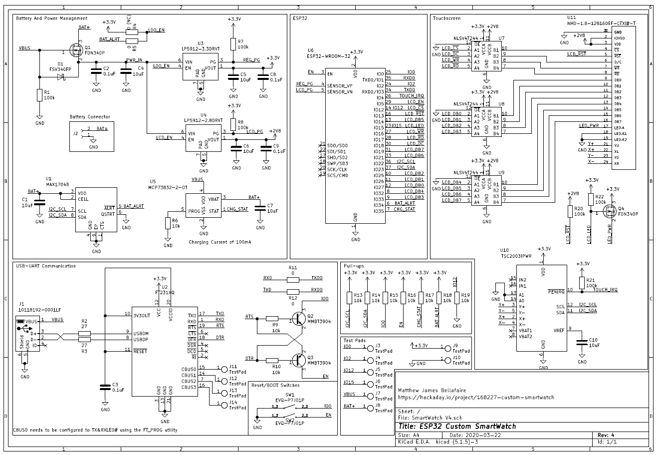
So lets start with the full schematic:
![]()
I made sure to put everything into blocks just to simplify the schematic a bit (and kept everything on one page). The most significant change from Revision 3 is the change from the ESP32 D4 Pico to the ESP32 WROOM module. Using the pre-built module allows for an easier design process and doesn't necessitate me routing any RF traces or dealing with any of the other black-magic that is WIFI radio. Switching to the module was a reluctant change on my part however, since the module occupies twice the boardspace of the D4 Pico. There's also the issue of soldering components together, and using the module will make hand-assembly marginally easier overall.
One major goal of this project is to have everything required by the smartwatch rolled into the smartwatch itself, so programming and charging need to be on-board and accessable by a USB connector. The rationale behind this is in line with the original project goal, this watch should be hackable on the fly and be able to perform any function it's hardware is capable of. The obvious cost of this being board space, so let's go through the board as it stands here.
From Revision 3 the USB-to-UART communication remains almost identical with the exception that this design uses the FT231XQ instead of the FT231XS. The only difference between the two IC's is the package, moving down to the QFN of the FT231XQ saves some board space for all the exciting new features.
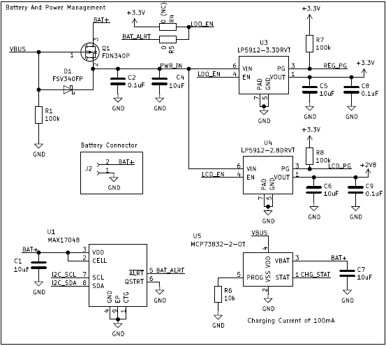
Power Management Block
![]()
The power management block rolls together battery monitoring, charging, and regulation of the power. Starting from the upper left the circuit now selects between battery and VBUS when plugged into charge, this should allow the battery to charge without also being loaded by the operation of the watch itself. Two linear regulators are used to supply power to the circuit one supplying 3.3V and the other supplying 2.8V for the LCD. Battery charging is performed by the MCP73832-2 which charges at 100mA with a 10k resistor on the PROG pin.
The battery is monitored by the MAX17048 which is able to estimate battery percentage and shut down the regulators if a fault condition is detected. Information is fed back to the ESP32 which will handle most of the power management in normal operation. The regulator's power status and the MCP73832 charge status are also connected to the ESP32 allowing the software to know if one of the regulators drop out.
The dropout of the regulators in this design is a crucial feature, the 3.3V regulator drops out at 3.48V (in the absolute worst case) which is below the 3.6V maximum voltage the ESP32 can handle, this way the watch can operate all the way down to a battery voltage of 3.0V.
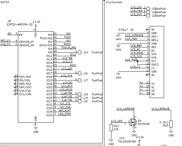
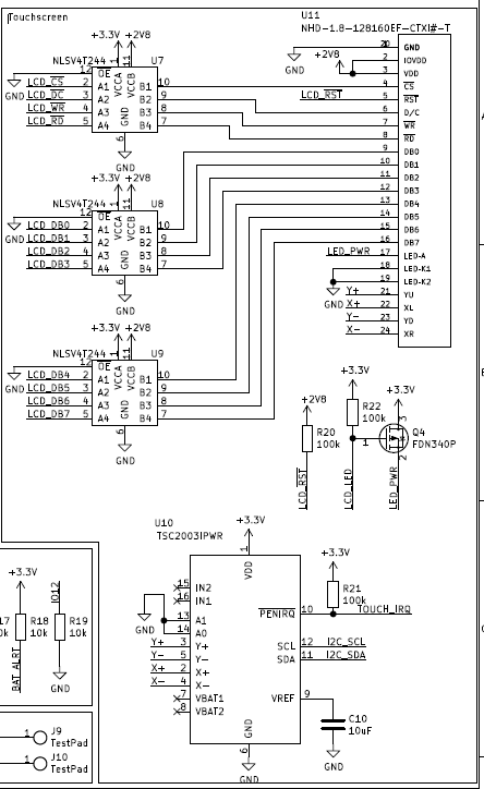
Touch Screen
The touch screen itself is a 4-wire resistive touch screen with an 8-bit parallel interface. To support the touch functionality the TSC2003IPWR was selected to handle reading touch input. The TCS2003 communicates over I2C which was essential since every IO available on the ESP32 is already occupied. Another advantage to this IC is that we can use the PENIRQ pin to wake up the ESP32 in deep sleep mode. The TOUCH_IRQ pin connects to one of the RTC IO pins of the ESP32, allowing for the module to sleep until the screen is touched.
To support the 2.8V logic level of the touch screen all data traveling to the LCD moves through level shifters. For the level shifters this design uses the NLSV4T244 primarilly for their small form-factor to save board space. Finally the LCD's backlight is controlled by a single P-channel mosfet which is connected to the ESP32.
I may look for other touch screens, however this is the smallest I could find available from digikey.
Power usage
Since the last watch didn't go too great with power useage I decided to take a look at the design more closely before moving onto laying out the board. This won't be the most in-depth analsysis of the circuit but there is some good information contained here about the design.
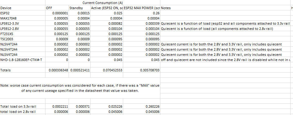
To estimate the power useage of each component I used Excel to tabulate the power useage of each IC under various conditions of load (off, standby, active, and maxpower) and use these number's to estimate current draw over time.
These values were obtained from the datasheets of the various components, but are not values that can be 100% relied on in some cases. More-or-less this excel sheet represents a "ballpark" of power useage. I plotted these current-use values in excel and obtained an estimte of power useage.
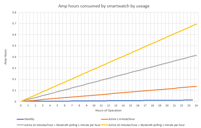
This assumes that "active" is the watch being used but not communicating over bluetooth or wifi. "bluetooth polling" assumes the watch is drawing the maximum power shown in the above table. Using this graph I can estimate the size of battery required for a given run-time of the watch, the previous design used a 300mAh battery which if used here would yield a battery life of anywhere between 10 and 18 hours depending on useage. I haven't fully decided on what size battery will be used in this revision but it'll most likely still be in the range of 300mAh.
That's everything I can think of to talk about in Revision 4. All that's left is to get the board made and start over on the software. See you in the next log!
-
Battery Management and Other things I've been browsing Digikey for a solution to
03/22/2020 at 03:01 • 0 commentsIt's been a weird week for me but I think it's time to get back to work on this project with some of my down time. Recently I've been looking into battery management for this project. In the previous revision battery management was handled entirely as a subsystem with very little input from the micro controller. While I still like the idea of the battery management system running semi-autonomously it often resulted in the entire watch shutting down prematurely or failing to easily recover from UVLO.
My goal for the battery management system in the next revision of this project is to have the entire system controlled (in some manner) by the ESP32 on board. Additionally proper battery monitoring would be useful, currently battery voltage is measured directly by the ESP32 ADC which is only an approximate measure of charge state.
I've been looking at battery monitors and I'm planning on using the MAX17048 to track the battery and control the power management circuitry. The primary advantage to the MAX17048 is that it allows the ESP32 to accurately read the battery percentage over I2C and thus control the battery management circuitry. It also allows for the undervoltage threshold to be configured which is a great advantage. Overall i'm looking to have full control of the battery management system, preventing the issues encountered with the previous revision that would result in power circuitry disallowing proper startup.
As for the display I've decided to ditch the LCD module altogether and go with something a bit more proper (albiet more involved to program). For the next revision I'm planning on using the New haven display NHD-1.8-128160EF-CTXI#-T which has a touch screen resistive pannel already on the LCD and is practically the only good touch screen I could find at this size. This display uses a hotbar connection, which saves the bulk of another connector and should make the connection fairly strong. However ditching the module means that I also needed to pick out a seperate resistive touch controller (also on the i2c bus), I'm using the TSC2003IPWR for this but may end up changing that depending on board space requirements. Another adantage is that this new display uses an 8-bit parallel interface, meaning that the overall time required to write to the screen should be reduced by an order of magnitude. I'm looking forward to the capabilities this screen will allow, but it won't be the easiest thing to interface with.
At the moment I'm nearly ready to move into laying out the board, just want to give everything a 3rd look-over before ordering any boards or components. I'll make another log soon about the finalized schematic.
See you in the next log.
-
Identified issues with Rev 3 and other planned changes
03/14/2020 at 17:43 • 0 commentsI want to start off this log by saying that the Revision 3 board works fine, it accomplishes the basic goals of the project and performs its function well enough. With that said however, I've identified a couple of issues that I’m going to fix in a new revision soon enough here.
I've annotated the current schematic with the changes that I'm currently planning on implementing but I want to put them here along with some extra information and some planned changes. As of right now the change list looks like this:
- change MCP73811T charging current to 200mA using prog pin - remove PMOS for LCD backlight control - configure power-in circuitry so the device can run directly from USB power when charging - battery voltage sensing solution to something external to micro controller - Replace MAX9065 with new battery monitor (or disconnect as a undervoltage shutoff) - Implement Power-off functionality for accelerometer and LCD. power drain of these devices in standby is too high - Ensure that any touch input interrupt is attached to an RTC GPIO pin so that the ESP32 doesn't have to poll the pin
The purpose of this log is primarily to document some of the changes that I'm planning on making and the mistakes that were made with the current design.
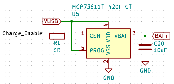
- change MCP73811T charging current to 200mA using prog pin
![]()
This one I should have caught. In the battery charging sub-circuit I configured the prog pin to VUSB for simplicity. The problem with this is that the charge current for the battery cannot be reconfigured, in the current circuit configuration the MCP73811T charges the battery at a blistering fast 500mA which on top of not being good for the battery also creates trouble with the USB connection (USB doesn't exactly like 500mA being drawn while communication is happening). The result of this configuration is that the smartwatch will not communicate over USB while the charge enable pin is reading a high voltage. Originally, I planned for this and configured one of the CBUS pins on the UART bridge to control the battery controller, this solution kind of works but occasionally it will cause problems and result in the device not connecting properly to the PC.
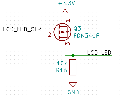
- remove PMOS for LCD backlight control
![]()
The board was designed before I received the LCD modules that were chosen to be used in it. The result is that I had to infer the pin functions from the Bangood page (because you know, tons of documentation there). I was under the mistaken impression that the LED control pin was the anode of the LED, this appears to not be the case and the LCD module has its own internal switching circuitry. The result is that this entire sub circuit is redundant and LCD_LED_CTRL can connect directly to LCD_LED.
- configure power-in circuitry so the device can run directly from USB power when charging
Currently the entire circuit is connected to the positive terminal of the battery, even when charging power is being drawn from the battery (and the battery charging IC). While this doesn't cause any immediate problems that I've observed it is worth fixing.
- battery voltage sensing solution to something external to micro controller - Replace MAX9065 with new battery monitor (or disconnect as a undervoltage shutoff)
These are more-or-less the same thing, currently my battery management solution is to use a MAX9065 window comparator to automatically shut off the LDO that powers the ESP32 circuitry. The result of this is that the MAX9065 operates essentially separate from everything and if the battery voltage is too low or too high the entire smartwatch cannot function at all. In addition to this the current battery sensing solution simply uses the ADC of the ESP32 which can only approximate the battery voltage (and not very well). In the next revision I plan to choose a more complete battery management solution (Next log or two may cover how I'm going about selecting the battery management chip).
- Implement Power-off functionality for accelerometer and LCD. power drain of these devices in standby is too high
Everything draws power in a circuit, I have never attempted any design where power usage is a significant concern (all the more reason I enjoy this project) so I was somewhat blindsided by this one. Although the ESP32 can be put into deep sleep to conserve a significant amount of power the LCD and accelerometer remain active and drawing power. Currently there is no reason for the LCD controller to remain active while the ESP32 is in deep sleep and so the LCD itself should be disconnected from power to prevent the power draw.
- Ensure that any touch
input interrupt is attached to a RTC GPIO pin so that the ESP32 doesn't have to
poll the pin![]()
Finally, the LCD has a PEN pin which indicates when the touch screen is being touched, currently it is connected to the ESP32P through IO10. The result of this placement of the pin is that the pin must be polled by the microcontroller by waking up from deep sleep. The ESP32 ULP supports external wakeups on specific pins, using these external wakeups would be far more efficient for my purposes.
As a final remark, I may switch the design from the ESP32 D4 Pico to the ESP32 WROOM or similar modular solution. While the Pico is fantastic in terms of size it is difficult to work with, in addition to this I know next to nothing about RF design and had a lot of difficulty selecting and laying out an antenna on this board. While the current smartwatch WIFI works better than expected I feel uneasy about using it without knowing more about any stray signals it may be throwing off. Switching to a pre-packaged module should save a significant amount of trouble but presents its own layout challenges given the limited board space of this project.
Overall, I fell into a lot of traps with this project and plan to take things slower going forward. I never really look at failures in my projects as something bad, generally it’s the failures that teach me the most and this project overall has pushed me to learn quite a bit. I plan to make more regular logs about the progress and maybe even sub circuits of the design just for the purposes of documenting what's happening with this design.
Either way, that's all I had to write about this, see you in the next log!
-
Progress Update
03/08/2020 at 23:30 • 0 commentsIn my free time I've been working with the smartwatch board and software to try and get things into a useable state before I move onto writing some more "permenet" code. At the moment a good deal of progress has been made but much of it isn't worth talking about just yet.
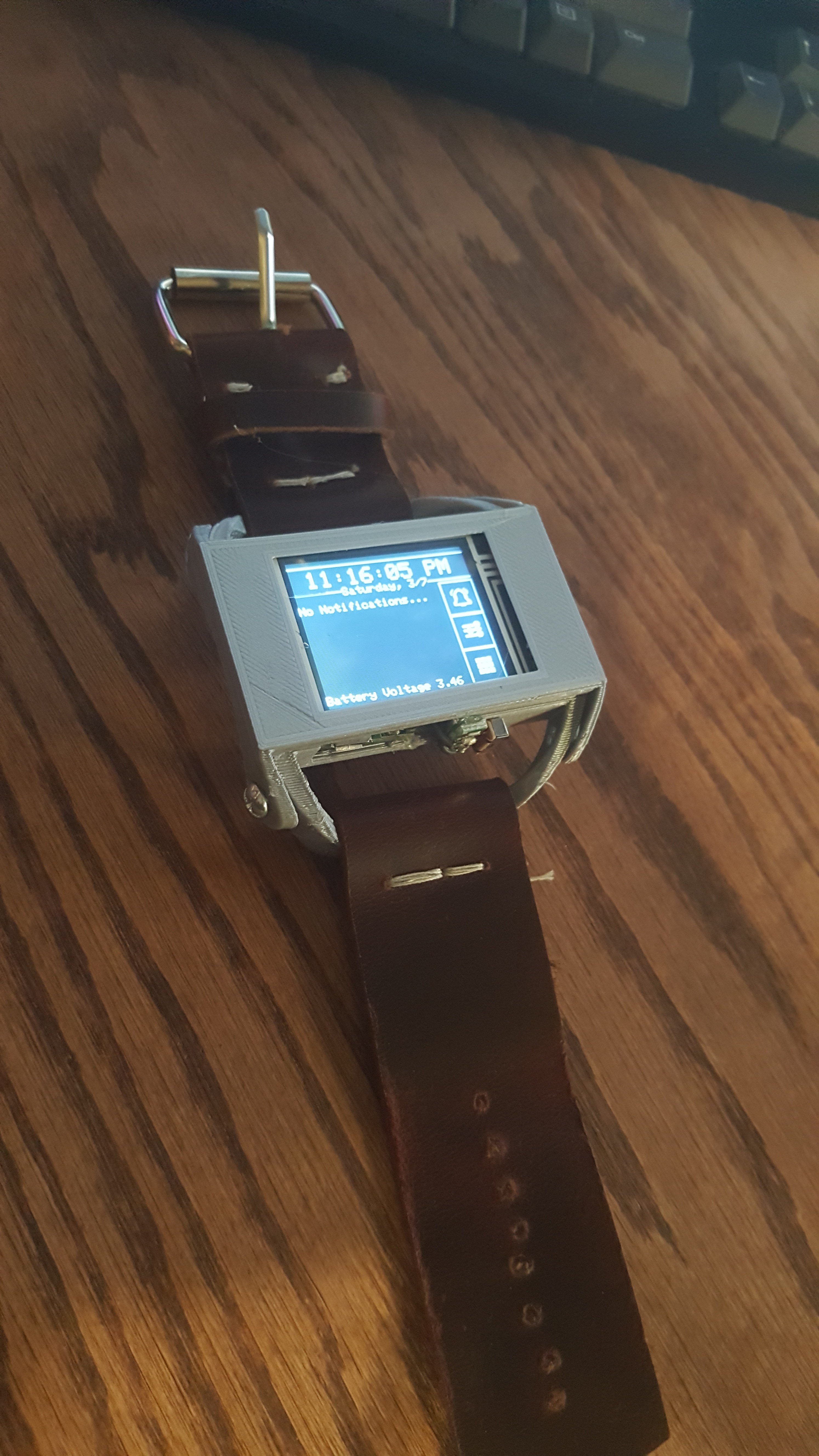
I've also gone through a few iterations of the smartwatch body to try and get something more appealing than what I showed in the last log, so far I'm very happy with the results.
![]()
The case itself fits over top my wrist. The entire body is 3D printed in 2 pieces. In terms of size its roughly where I want to be with this project, however the screen could still be bigger (ideally it takes up the entire top face).
![]()
I've been looking into the sleep modes used on the ESP32 and I'm still working on making the main loop as efficent as possible, at the moment the watch itself has a 300mAh battery giving it a lot of potential. However, since I'm not currently utilizing any of the sleep modes in the software that's currently running the battery life is less than Ideal. Currently the watch can run for about 6 hours without being charged with the ESP32 running without any sleep functionality. I'm hoping that it's possible to manage 24 hour battery life by managing the deep sleep mode of the uC but it requires me to rewrite a significant segment of code.
On the subject of circuitry I've made some minor bodges. Previously a P-channel mosfet was used to control the LED backlight, this was unncessary and it has since been removed from the board and replaced with a jumper. There also seems to be an issue related to the reset button, it appears that pressing the reset button results in FT231XS UART Bridge also resetting or otherwise loosing power. The reset issue is new, when the board was originally assembled it did not have this problem and I can only assume that there's a bad component on the board or a short that is hidding somewhere. For the time being I've simply removed the auto program functionality and resorted to programming by holding the BOOT button until the issue is resolved.
For the moment this project is in a kind of weird place, the progress is good but there are a lot of things that need to be implemented and I'm kind of scrambling to decide what the most important features are and what order I want to tackle them in.
The end goal of this project is basically to have a micro-controller based smartwatch that can be easily reprogrammed and expanded with extra software additions. I chose the ESP32 specifically for its community support to achieve this goal. The expected downside of the ESP32 was the power consumption and that's going to be the biggest hurdle to overcome. From what I have read in the documentation the goals of this project should be attainable, if the power consumption becomes too big of an issue I'll most likely switch to a different uC and essentially start over from the beginning.
Once the watch is working well I plan to use this watch as a kind of WiFi remote for multiple other projects that are in the planning stages. The end goal is to have something that resembles a tool more than a smartwatch while still having the functionality of a typical smart watch.