Matthew James Bellafaire
-
been awhile
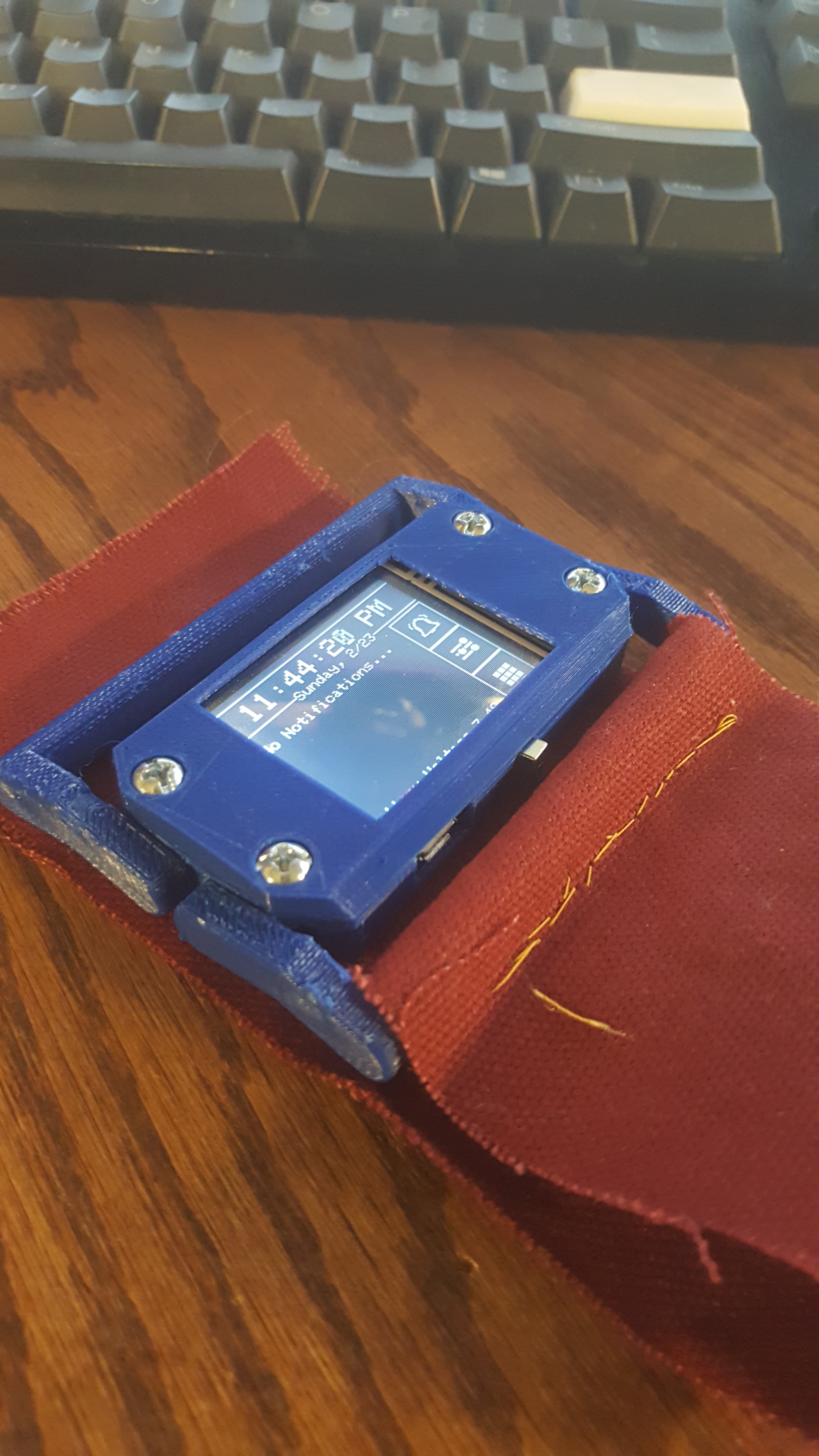
02/24/2020 at 05:46 • 0 commentsIn the last 2 months the work on this project has not stopped, in fact quite a bit has been poured into getting a design working. I'm happy to report that the REV3 boards work! (yeah there was a Rev 2 that went completely un-mentioned).
This project has been taxing on my free time, I really enjoy the challenge of it and the idea of the end result. However, I've made some fairly grave errors so far in this project. So far the progress on this project has been plauged by the UART to USB communication IC's I've been using. In the first revision the CP2102 seemed to fail due to reasons I couldn't determine (although I suspect they relate to soldering I never managed to get one to even enumerate on my computer). After the failure of the Rev 2 I did some redesigning, and used a new UART bridge and double checked my connections and design choices. The board was ultimately a failure, although it was a good step foward, Rev 2 was able to communicate over USB, however this was only after scraping off a few traces and adding some bodge wires.
![]()
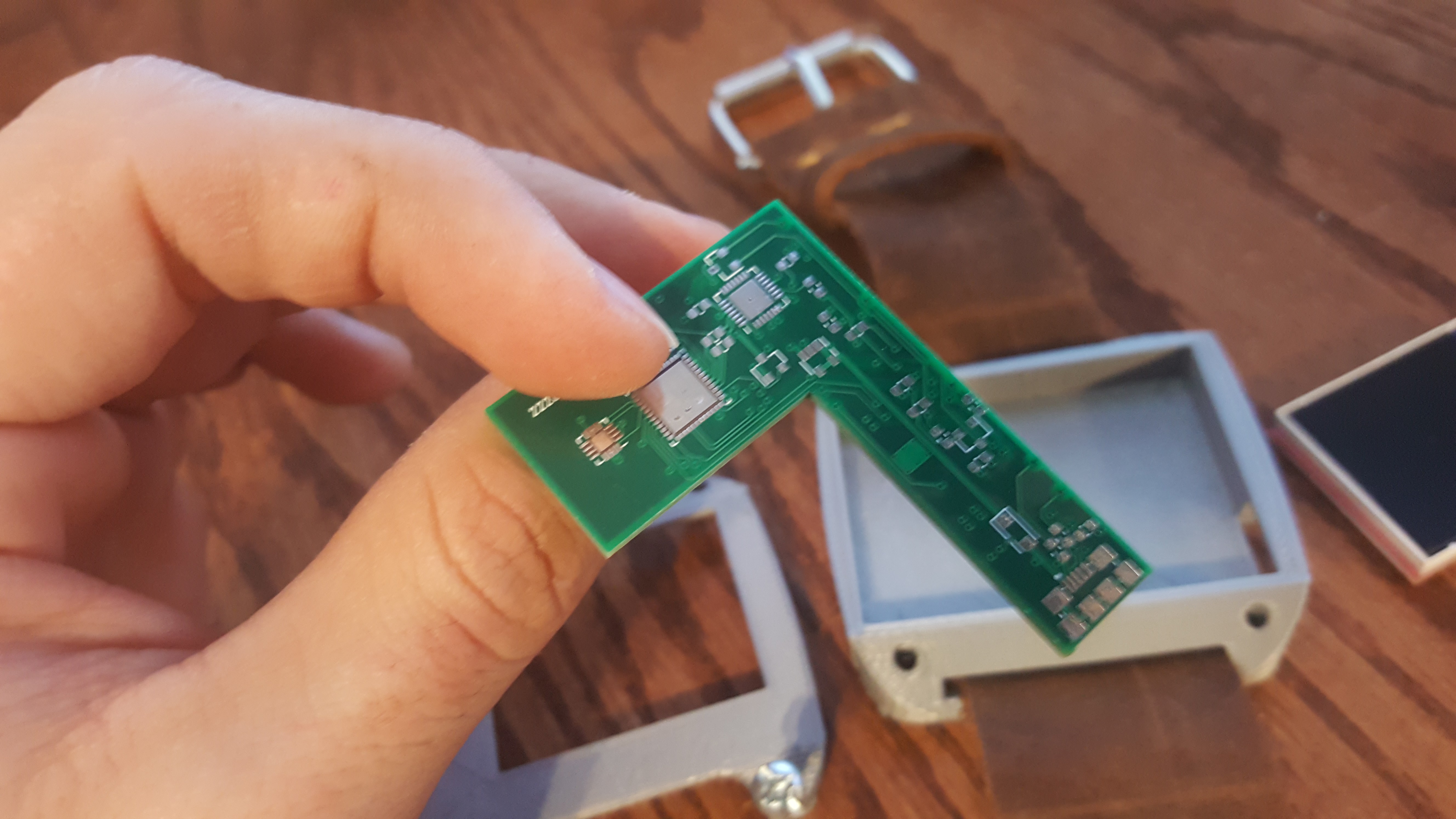
All and all though I'm happy to report that the 3rd revision does work. Credit where it's due I borrowed a bit of a design by mike rankin (https://github.com/mike-rankin/ESP32_Pico). The current 3d printed case is pretty rough (everything looks cooler in CAD) and will most likely be replaced in the next day or so.
I have some software written and a decent framework thought out, but overall most of the code is still unwritten. I've also begun work on an android app to communicate between the smartwatch and my phone.
For anyone interested all the files for this project are available on github at: https://github.com/Bellafaire/ESP32-Smart-Watch
See you in the next log!
-
Failure of Rev 1 And Lessons For Rev 2
12/08/2019 at 13:10 • 0 commentsIt's been awhile since I've updated the logs for this project (and that mostly has to do with the busy semester). In my free time I've been working with the watch trying to get something to work. I built up the board and tried to get it to work to no avail. Turns out in the original design the UART bridge was giving me issues. I've since switched from the CP2103 to the FT230X (which comes in a package that isn't QFN).
I am still unsure about what the issue was with the REV 1 board. all the power circuitry seemed to work fine (over voltage / under voltage / 3.3v LDO). However no matter what I tried the UART bridge would not be detected by my computer. My best guess is that it has to do with the distance the usb trace had to run (the L shape board made layout fairly tricky). Either way I've corrected as many issues as possible and was much more careful about handling the RF of the antenna. Another issue on the rev 1 board was that I forgot to define the soldermask pullback. This left most of my QFN packages without any soldermask between the pads (I was able to hand solder but it still took far too long). Either way there's a lot of improvements here (that hopefully amount to the board functioning). Here's the new board:
![]()
![]()
The header probably raises the most questions. In the first revision I decided to go with a 3 button interface for the watch. I've since decided that I would instead go for the ultimate goal of the project which was a full 1.8" touch screen. I finally managed to track down a touch screen that was the correct size, (From bangood) https://usa.banggood.com/1_8-Inch-LCD-Screen-SPI-Serial-Port-Module-TFT-Color-Display-Touch-Screen-ST7735-For-Arduino-p-1414465.html?rmmds=myorder&cur_warehouse=CN and have ordered 2 of them. Once I have them in hand I'll decide whether to order/redesign the boards. For now the project is just kind of on pause since finals are next week (and I'm waiting on parts). If the 1.8" screen is too small I may end up going with https://www.crystalfontz.com/product/cfaf240320a0024sc-240x320-full-color-touchscreen-tft-2-4 (which in general is much nicer but is many times more fragile).
I've decided to go with a single sided load due to how much of a pain assembling the double sided load was previously ( it made applying solder paste nearly impossible for smaller pin pitches on whichever side was assembled second). Either way that's most of the changes, I plan to release all my schematics/board files/BOM when I finally have working hardware to program.
I have a long holiday break coming up and I plan to work on 3 of my current projects then bundle the board orders together. So it may be a bit before I have these in hand. Either way, see you in the next log!
-
Everything's here
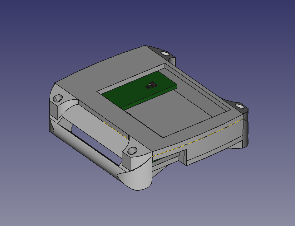
11/18/2019 at 18:00 • 0 commentsWell, everything's here, time to check fitting. Thanks to the KiCAD Stepz export plugin this hasn't been too much of a worry. The basic idea for the design here is just to get everything together into one case, here's what I came up with:
![]()
The top of the shell is held together with 4 #6 screws and the strap wraps through the slot on the left. Overall this design is slightly larger than expected but there's a lot that I can (and will) cut out of it to reduce the size. For now it works.
With all that said the boards and stencil have finally arrived, they're looking alright:
![]()
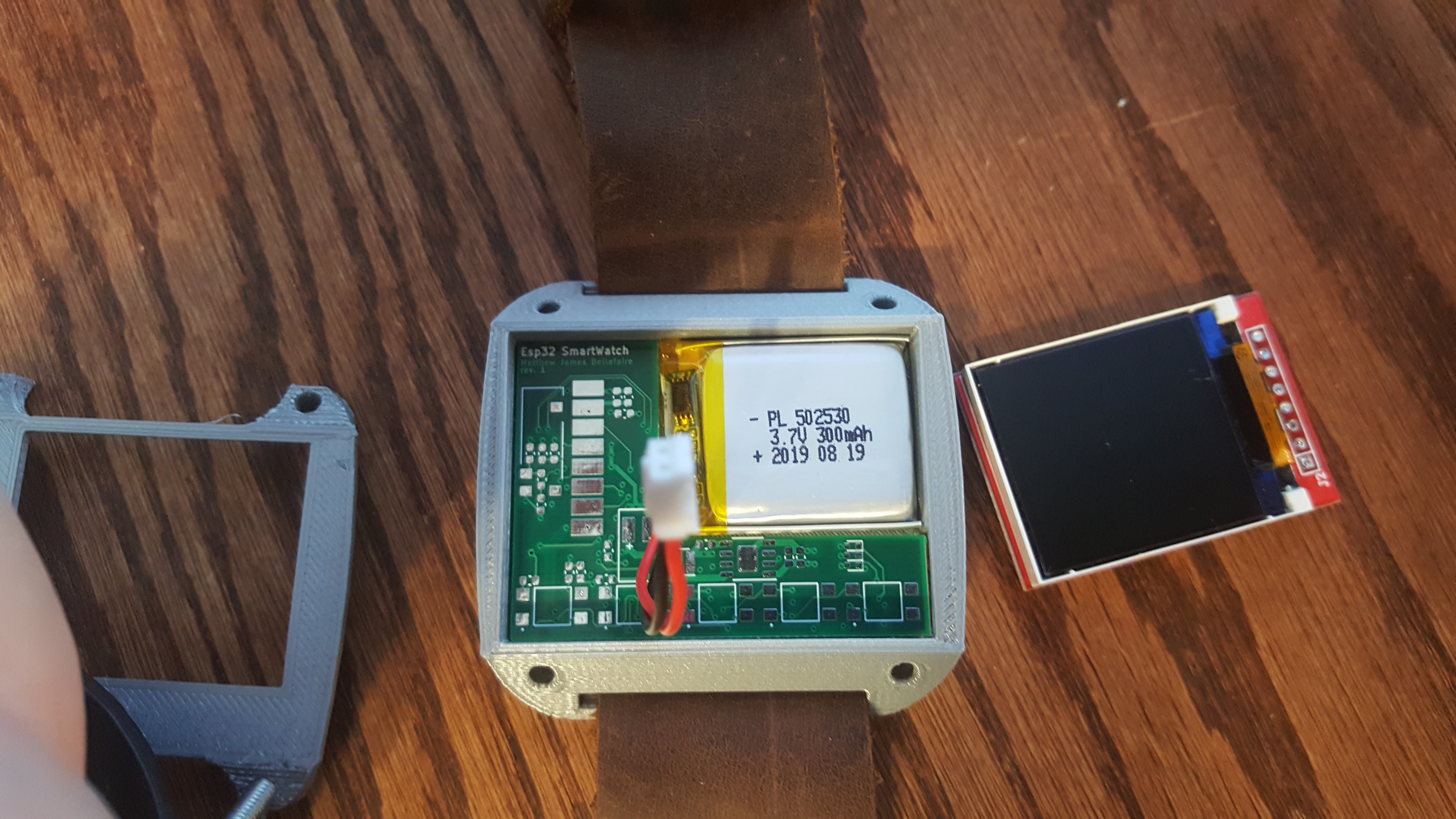
It's not exactly visible here but the soldermask pullback on the QFN packages is less than ideal, I'm worried about the overall difficulty I may encounter attempting to reflow these boards. However, every other visual inspection of these boards is positive. the overall fit is perfect in the case along with the battery:
![]()
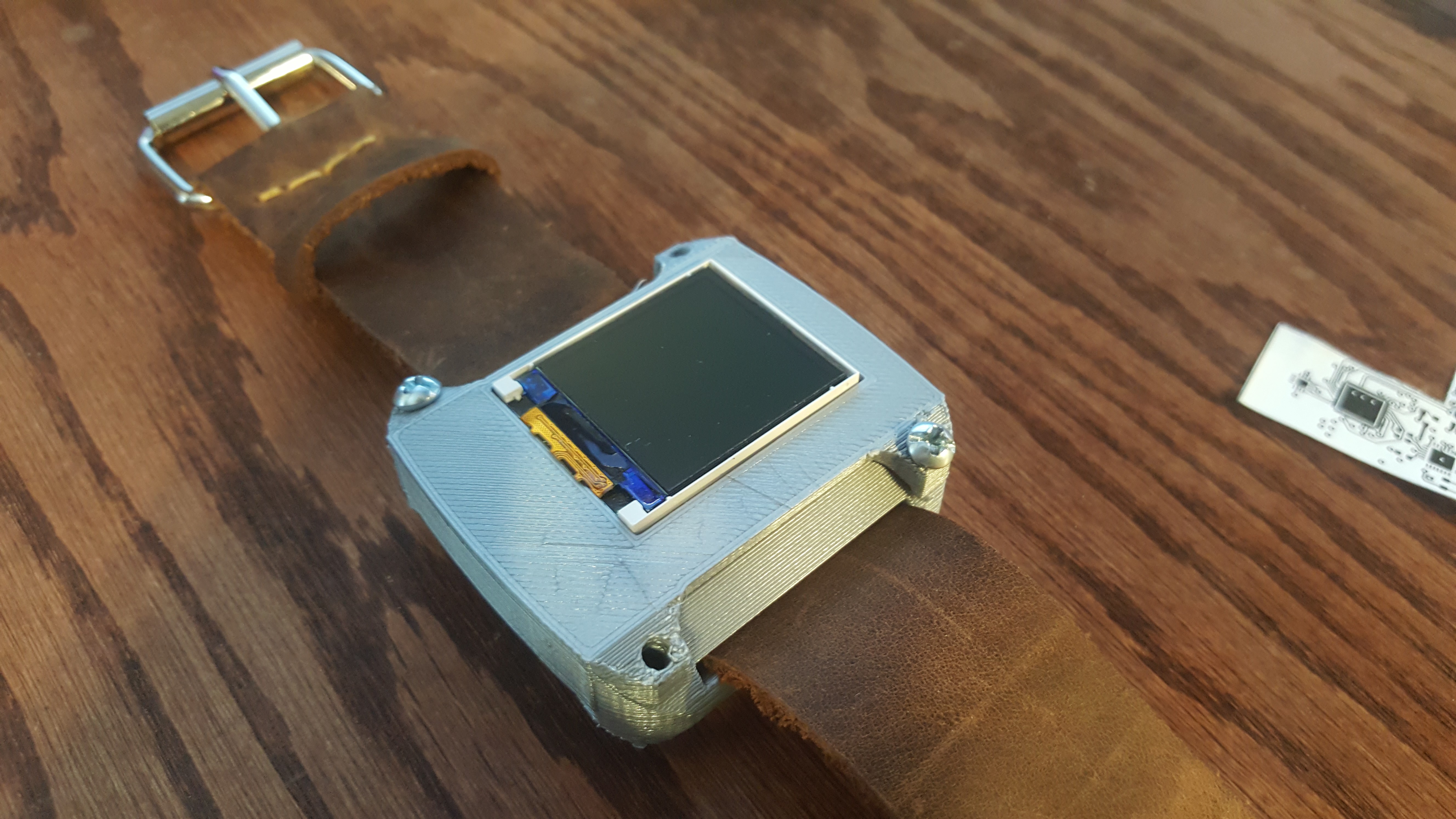
And finally with the top part and screen:
![]()
I still need to determine where to add the holes for the buttons, but overall this gets the job done for what I needed. At the moment my only complaint is that the watch is taller than it should be but I guess there's just some work that needs to be done there.
![]()
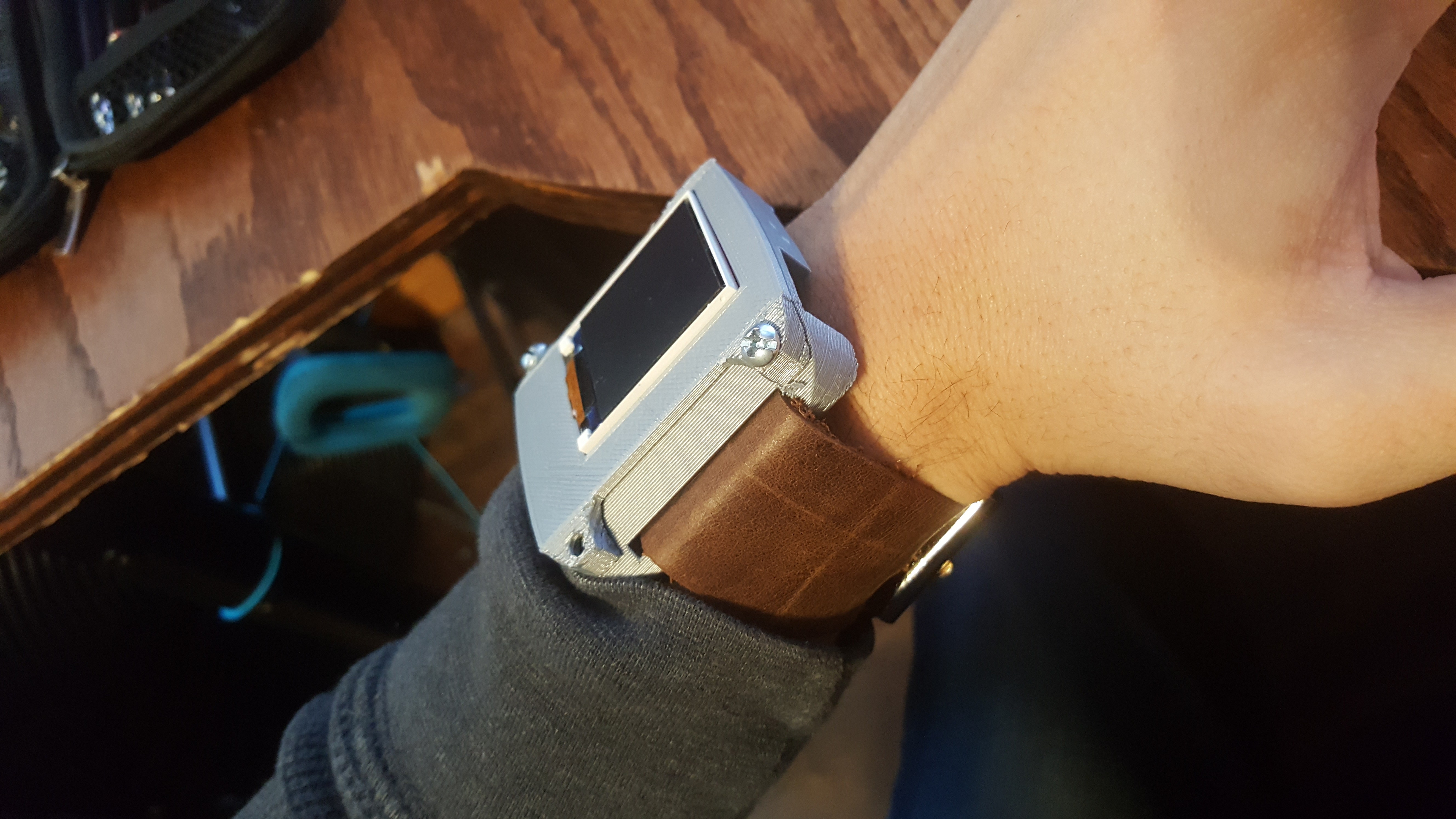
So far I'm very happy with how this project has been progressing. I plan to use this version of the watch for a decent amount of time to determine what improvements need to be made to the hardware. The final version will be more-or-less the same form factor shown here. Ideally the final version does away with the buttons and opts for a 2.2" touch screen panel, but I'll talk more about future plans for this project as soon as this phase is complete.
next up is assembly. -
Progress update, board completion
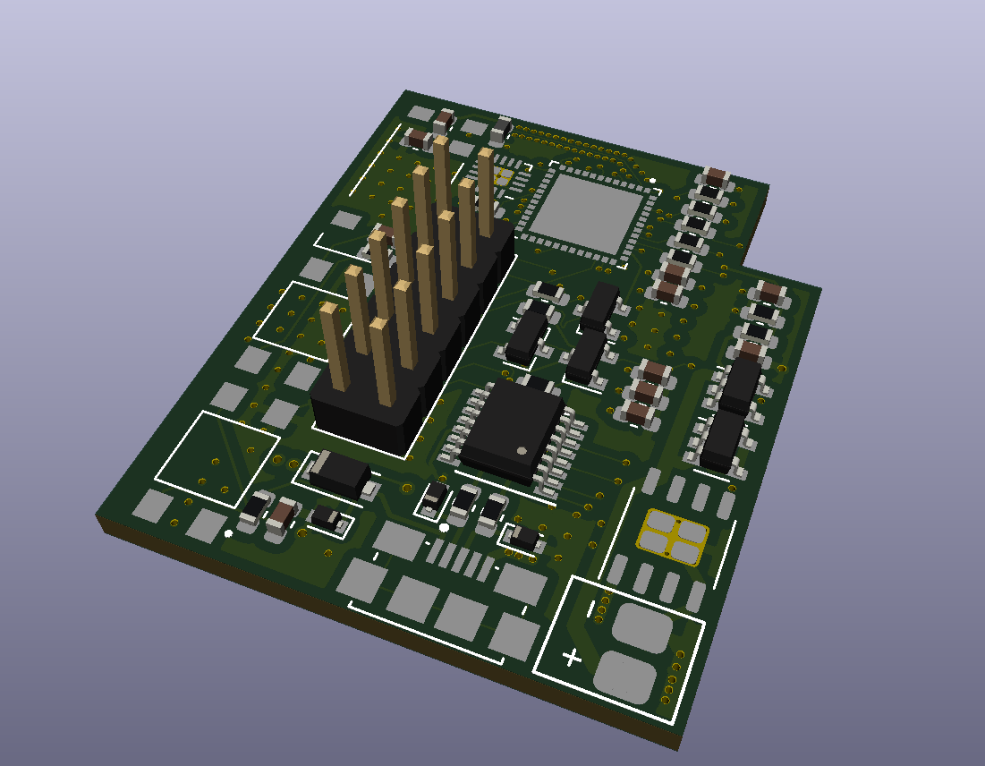
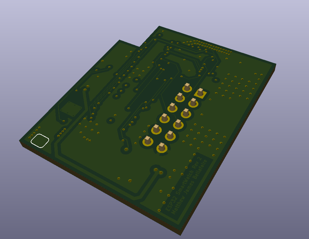
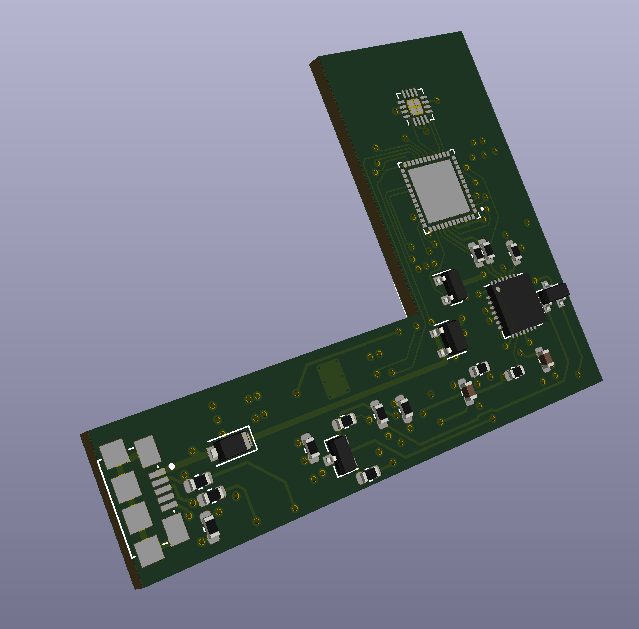
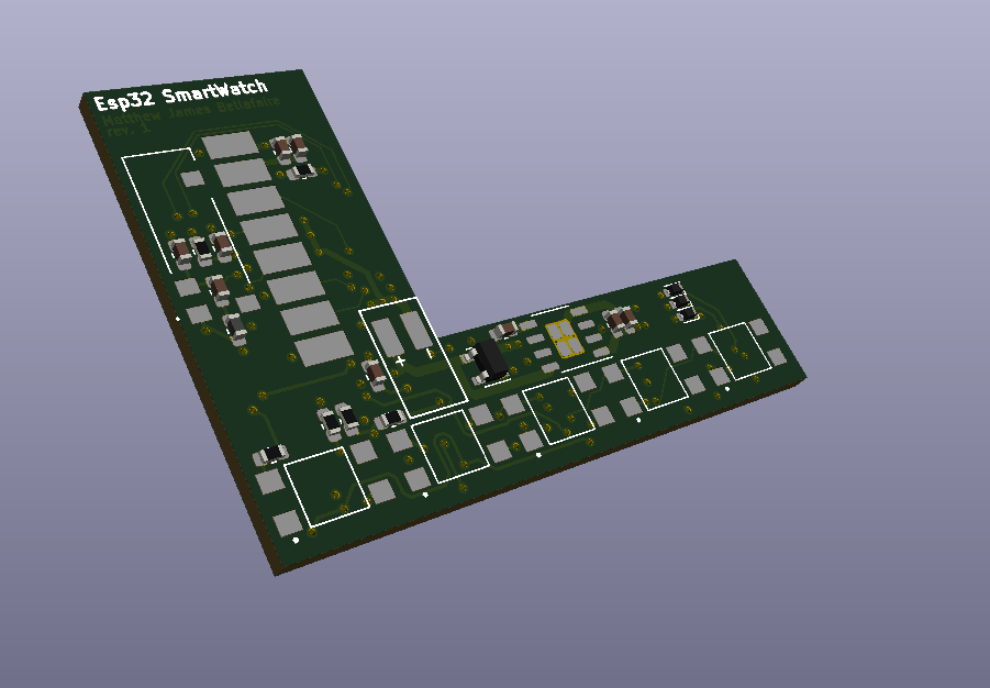
11/09/2019 at 17:25 • 0 commentsI've been working on this project about 1-2 hours every morning for the last 2 weeks, and a lot of progress has been made so far. As stated previously this project uses the ESP32-PICO-D4 micro-controller. The convenient thing about this micro is that it has reference schematics online, making the actual electrical design significantly easier (Also one of the clubs I'm involved with at my university wants to use it for most of our projects, so I wanted to get a jump on understanding using it in my projects). either way the board design is completed. Here are some glam shots of the 3D view KiCad has.
![]()
![]()
the large pads on the left side of the second image are solder pads for the TFT display (i'm going to wire those individually so the screen can be opened/closed easily In case i want to get into this for some reason. On the bottom we have 5 buttons. 3 are for actual interfacing and 2 are for reset/programming the micro controller. On board we also have a USB-to-UART IC so that this watch can be programmed and re-programmed anytime provided a micro usb cable is handy.
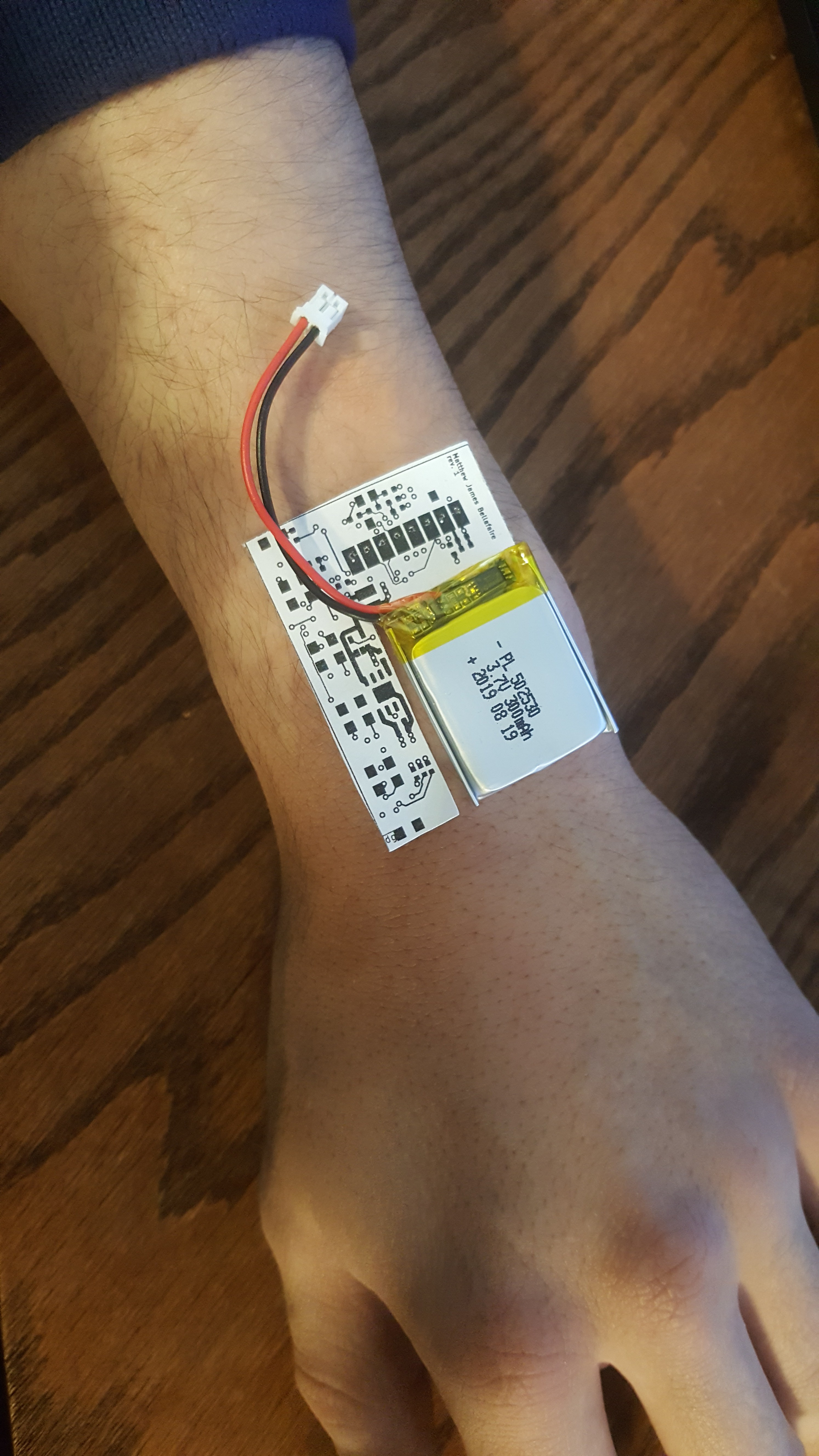
Now let's talk about size, because that's really what matters here. This project utilizes a 300mAh battery for power and a LCD TFT Module from amazon. Overall i'm happy enough with the sizing for a first revision, I've prioritized flatness over width to ensure that the watch doesn't look too ridiculous. Here's a scale printout of the board with the battery in its slot.
![]()
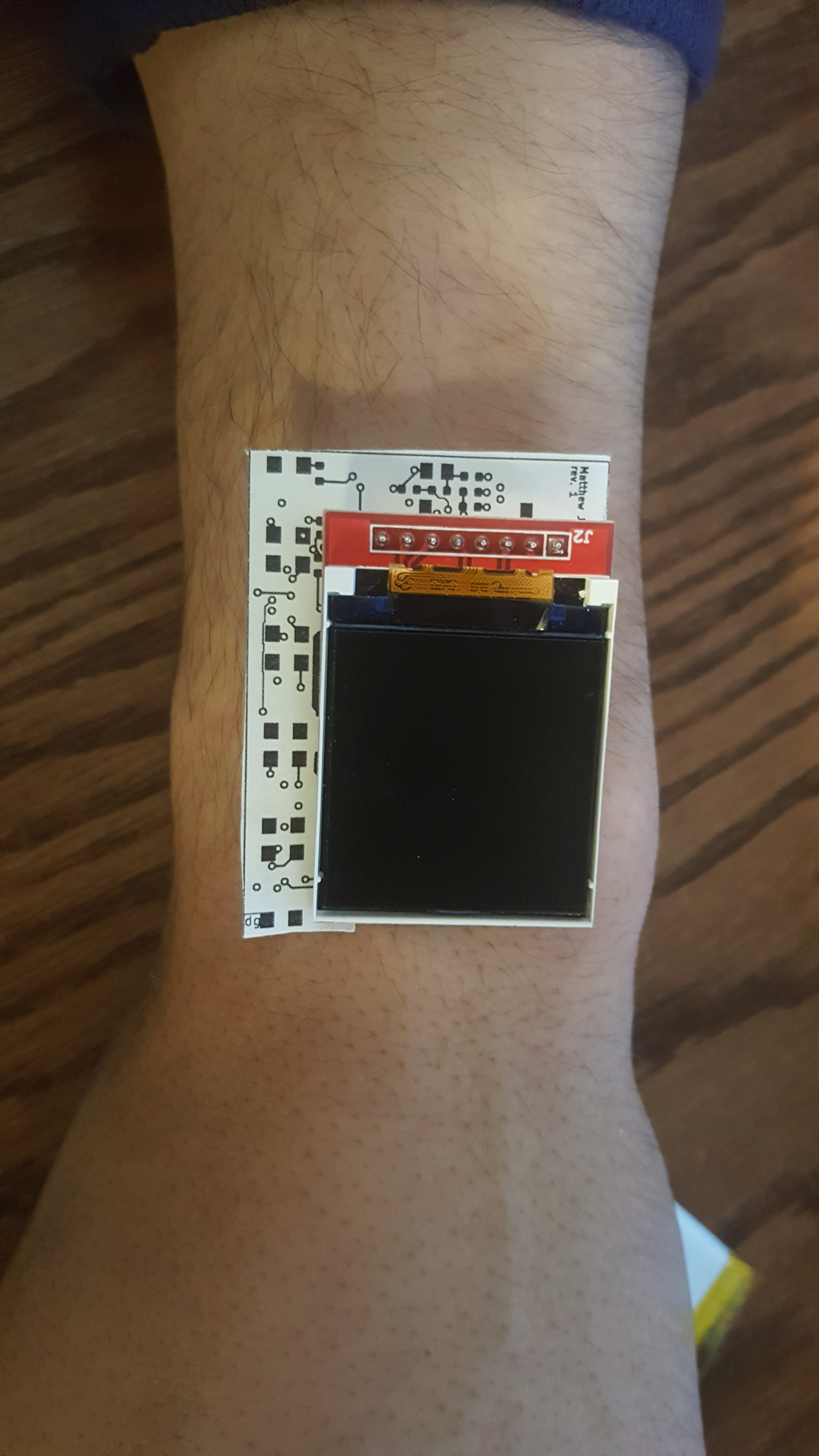
Overall I'm happy with the size overall (keep in mind I plan to do future revision and this is by no means the final version). When the screen is added on:
![]()
Ok so you might be wondering about that little part of the board next to the screen. That's the location of the 2.4GHz antenna for the wifi and bluetooth, and it's fairly tall (about 8mm) so to reduce overall height it lays next to the LCD screen. I'm fairly happy with this design overall, and I think that I'm going to have a lot of fun programming it. In the mean time it'll be about a week and a half before the 4 layer board comes in, until then all I can really do is wait and maybe draw up some plans.
-
Most of the way there
11/04/2019 at 13:24 • 0 commentsAlright, back at it again. I'm working on this project pretty consistently (about an hour or two a day) and the electronics are 90% of the way there. I'm just working out the finer details of the layout for the board.
I hate to admit it but it looks like the first revision of the board may be slightly larger than the screen. It's not exactly ideal but it does give me a platform to experiment with and write software for. I do plan for a revision two of the project maybe with some extra features but for now I'd like to just get some stuff on order.
Either way the main purpose of this log is to talk about some of the decisions that have been made for this project in regards to component selection.
For the main micro-controller this project uses the esp32 pico d4, with integrated wifi and bluetooth it has more than enough processing power and features to make this project do everything I want it to do. Also since it's an ESP32 there's a great amount of additional functionality I can add later as the needs arise. Power consumption is a bit of a problem with this chip, but I've done some looking into the sleep modes available on the esp32 and running with a 450mAh battery the lifetime should be good enough provided average use for a watch.
Now obviously power management is a big part of this project and there are 3 IC's used here that will serve to generate a stable (kinda) 3.3v.
- MAX9065 - window comparator for voltage monitoring of the battery
- mcp73811T - lithium ion battery charger (i just love this IC)
- S-13A1A33-E8T1U3 - 3.3V LDO regulator
Picking the LDO reg was one of the more difficult parts of the design process for this project. The ESP32 pico can handle voltages up to 3.6V easily and operate down to 3.0V. So the voltage dropout of the regulator needed to be less than .2v at operating current. Luckily I found the S-13A1A33 which fits the bill pretty well and requires a minimum of external components. I thought hard about using a buck-boost converter for this project, but the board space considerations put the nail in the coffin for that one.
In addition to the power management IC's the current design also includes an ADXL337 accelerometer which uses a 3-wire analog interface for each axis and should allow for the easiest interfacing. Power consumption this chip is also fairly low and overall should reduce the power consumption of the board. The current plan is to only activate the tft backlight when the watch is pointing upwards or when a button is pressed on the watch. This way the LED backlight can't suck too much of the battery life away. In tests so far this results in some fairly good power savings but as always its hard to tell without the physical prototype in hand.
Either way that's the design as it stands currently, I'll be releasing the rev 1 files as soon as I feel they're done.
-
Revision 1 Features and Goals
10/30/2019 at 12:23 • 0 commentsFor this smartwatch project I'm trying very hard to avoid adding too many features. I intend to do a few revisions of this project as I learn the skills needed to complete it. Recently I've acquired access to a proper solder reflow oven through a club at my university which allows me to construct boards using components that aren't hand solder-able, making a project such as this feasible.
Alright, lets talk about features (and mind you this is revision 1 I'd like to add more later on)
- Wifi/bluetooth connectivity
- 3 button interface (couldn't source a touchscreen at this size)
- 450mAh battery (USB rechargeable of course)
- 1.44" TFT display
More or less I want a micro controller on my wrist that tells time, and allows me to write my own extra code whenever I want. Naturally the biggest challenge here is going to be the PCB layout, everything needs to be thin so the board needs to have a cutout for the battery in order to keep a low profile. Overall I'm looking forward to this project.