 A. Noniem ⚙
-
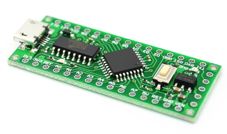
1Reduce Power Usage of Arduino
Remove the AMS1117 from the Arduino board it is the Voltage regulator which dissipates heat for voltage reduction.
![]()
We use a buck converter which takes less power.![]()
In this case it's on the right side of the board.
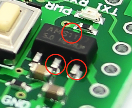
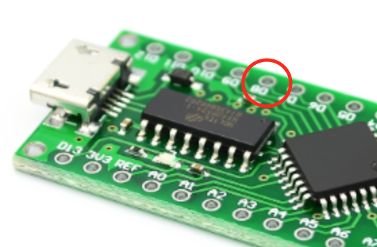
There are 4 pads on the board that will need to be "connected" in order for the board to work without this regulator. The 3 lower pads you can see connected to the AMS1117.
![]()
The center and right pad should be connected to each other and to the top pad. (invisible in the above image) Use a thin wire to accomplish this.
-
2Connect the Buck / Boost converter
Dissipating heat is very bad for efficient power consumption.
To lower the consumption we will use a Buck converter; actually a combination of a buck (Stepping down) and boost (Stepping up) converter that focuses on 5v output.
They are bigger and more expensive but enable us to select a power source ranging from a 3v CR2032 cell to a 9v block battery.If you want to know the workings of such a device check this youtube video:
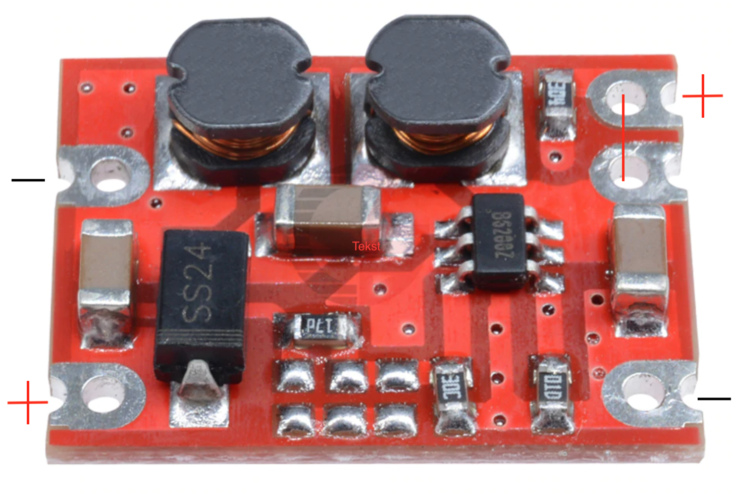
To continue; this is our Buck / Boost converter:![]()
The left side of this image will connect to the Arduino (will get to that in a minute)
The right side of this image you will need to connect to the Power connector (+ to red - to black)
NOTE: Make sure to bridge (connect) the two connectors on the right side that are close to each other (One of the Pin's is to "ENABLE" the buck converter).
Tip: Alternatively you can attach a on-off switch on this connector.
Now to the left side of the buck converter.
![]()
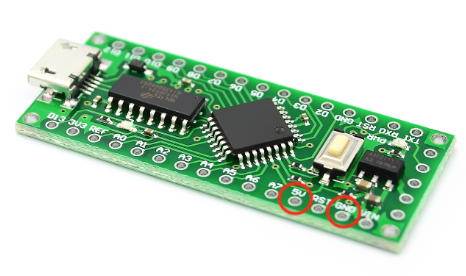
Connect the + wire to the VCC pin
Connect the - wire to the GND pin
-
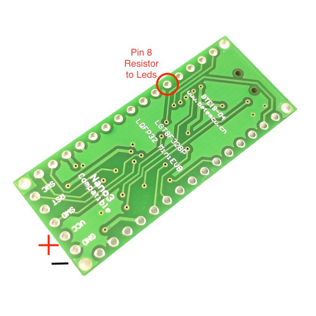
3Attach 300 to 500 Ohm resistor to Pin 8 (330 is an easy value I had here)
A resistor has no polarity so just make sure it is positioned on the top side of the board so your back side of the PCB remains nice and smooth. (Easier for attaching / piggybacking)
Make sure to isolate the wire for it not to touch any components on the board.
I usually use some shrinking tube to cover and insulate the resistor.
Heat it for it to make the tube shrink.
-
4Neopixel workings and connecting
Ok, first the basics; so -in short- "how a Neopixel works".
Neopixels or WS2812B work using what they call a shift register.
They are addressable through a serial protocol meaning you can send all pixel information to the first pixel which will only use the first N bit's to determine it's own color and brightness; after "processing" it's own pixel data it will immediately forward the remaining information to the next pixel(s) which will do the same.Check this video for some basics on NeoPixels; one of my favorite components:
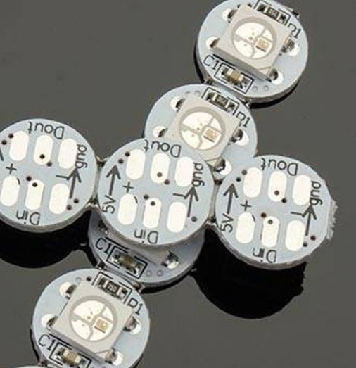
Our Pixel is the following formfactor:
![]()
The arrows indicate the forward direction of the signal.
The Din indicates the DATA IN pad.
The Neopixels normally require a pretty stable 5 Volt powersource but since our Buck / Boost converter and our 9v battery provide enough stable power on the output we will ignore the need for filters / buffers (in this case a buffercapacitor).
When increasing the amount of LED's it is advisable to add capacitors to the strip so the voltage drop when lighting to full white and full brightness will not make the power and voltage drop to the lower minimum threshold of the pixels to work.
TIP 1: When you experience pixels flickering or showing the wrong colors you either have a wrong resistor on the Din pin or your voltage is either too high or tool low.TIP 2: Make sure not to use a too thin wire gauge because that could make the voltage drop due to internal resistance or length.
![]()
As a power source I took the (+)5v of the Arduino and the (-) GND of the Arduino.
Vin could be used as well since we soldered a shortcut between the INPUT and OUTPUT pads of the AMS1117.
Connecting the first pixel is easy:
1. Attach + 5v wire to the + pad
2. Attach the GND (Ground = - ) wire to the - pad.![]() In an earlier step we connected both a resistor and a wire to this PIN. (Pin 8)
In an earlier step we connected both a resistor and a wire to this PIN. (Pin 8)
The last step is connecting the Data pin of the arduino to the Din of the NeoPixel.
For connecting any followup Neopixels we connect the Source NeoPixel (being the first pixel as seen from the Arduino) to the Destination NeoPixel using the following scheme:Source Pixel Destination Pixel +5v Out +5v In GND Out GND In Dout Din Use the double sided acryl tape to stick the pixels to the mask.
Make sure to position them so they will not shine in your eyes yet light the outline of the "skull"
TIP: I often use "Hot Snot" or Hot glue to fixate cables and cover the soldered joint with the PCB so the wire won't break at this position. -
5Uploading the skech
Connect the Arduino to your computer and upload the sketch that is added in the files of this project.
ENJOY!
Scary Scull - Haloween
Everyone is busy but when joining my daughters this year in the Haloween walk I wanted something nice, special and easy to make.

 In an earlier step we connected both a resistor and a wire to this PIN. (Pin 8)
Discussions
Become a Hackaday.io Member
Create an account to leave a comment. Already have an account? Log In.