-
Bah!
11/20/2019 at 12:51 • 0 commentsRats. Just remembered RPi GPIO is not 5V tolerant, so will need a few extras to interface between it and my circuit...
The PGOOD line should just need a pair of resistors. The nSHDN line might be a bit trickier...
I've chosen to use GPIO17 and GPIO27 which are both pins with pull-downs by default, with a value of about 50k-60k ohms if the internet is to be believed. That means I only need another 30k-50k or so in parallel (i.e. external pull-down) in combination with the 10k series already in the circuit to ensure the voltage on these pins doesn't exceed 3v3.
-
Success! I think.
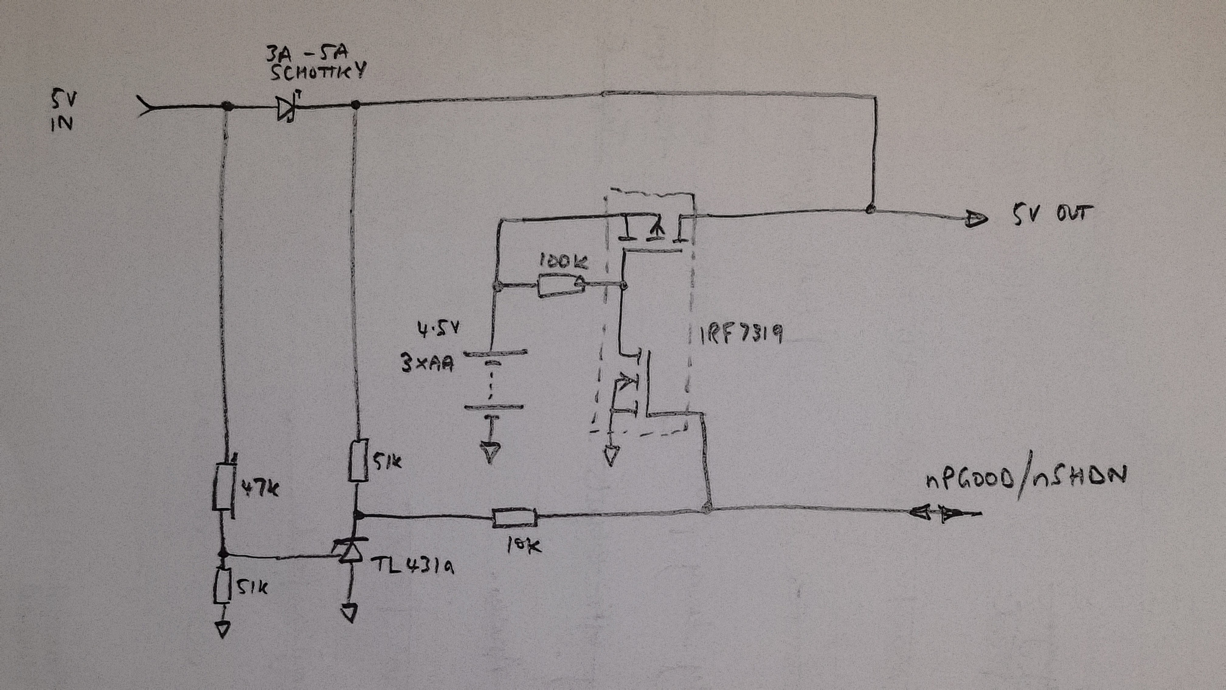
11/15/2019 at 16:02 • 0 commentsAfter a couple more attempts I think I've got the fail-over power supply working, using the dc-dc switcher module. I had to modify the module in two ways:
- bring out the ENable line so I can control it
- remove the trimmer pot and replace with fixed value resistors to give ~5.5V out
- remove the 0.1uF cap on pin 8 so that the 'soft-start' feature is disabled. Without this the switcher takes ~15ms to come up, leaving a nasty gap as it takes over from the mains supply.
![]()
Had a play with possibly swapping out the main Schottky for a MOSFET, but it's tricky without resorting to a complete 'ideal diode' circuit (three transistors, two resistors). If it bugs me I might just buy an ideal diode module.
-
Hmm, kinda works
11/08/2019 at 15:35 • 0 commentsI built up the power loss protection circuit, made a few tweaks, and tried it with a very modest load (only 5ohms, i.e. 5W) and the poor AA batteries droop badly and cannot hold up anything like 4-4.5V. I'm getting more like 3.6V.
So maybe a change of tack? I have a little dc-dc converter based on the MP2307, which is supposedly good for 3A. It's hardwired to produce 5.0V at the moment, and therefore requires about 6.1V in. I'm thinking what I might do now is use a battery with more cells (possibly 6?) and the dc-dc converter. I can do away with the P-channel MOSFET since I can now use the enable line on the converter to shut off the power (leaving just 0.3uA standby current). I should now get much better supply regulation for the 10-20secs while the Pi shuts down and as the batteries droop.
I've bodged something together quickly on the bench, and it nearly works except that the TL431 cathode voltage doesn't rise fast enough to enable the dc-dc converter, before the rail supplying the TL431 falls and everything goes off. I could supply the TL431 direct from the battery, but that would flatten it in weeks.
-
Here we go again...
11/03/2019 at 15:01 • 0 commentsAaarg. Must stop finding problems to solve...
The solution was looking promising: RPi4 running OpenMediaVault coupled to a pair of SSD's in a RAID 1 configuration, like this YouTube video or similar. All the benefit of Gb Ethernet, USB3.0, SSD speed, and mirroring for robustness. Sweet. Total bill so far about £130.
Then I realised about power loss corrupting the RPi image, and worse, the SSDs - especially cheap ones like I'd chosen. Balls.
So what I need now is a battery 'hold-over' supply. Not quite a UPS (I don't need it to run for hours and there's no need for a rechargeable battery and all that), but just for the 10 secs or so for the RPi to shut down cleanly. And a mechanism to tell it to shut down. And a way to cut the power once it has shutdown so the batteries aren't run flat. Oh, and it must also come up again cleanly once the main power is restored. Phew - anything else?!
This forum post indicates that the Pi's supply should ideally be between 4.7V and 5.25V, at up to 2.5A, though 4.0 to 5.5V might work. The PMIC's abs. max. is 6V. The official datasheet for the Pi just says 5V.
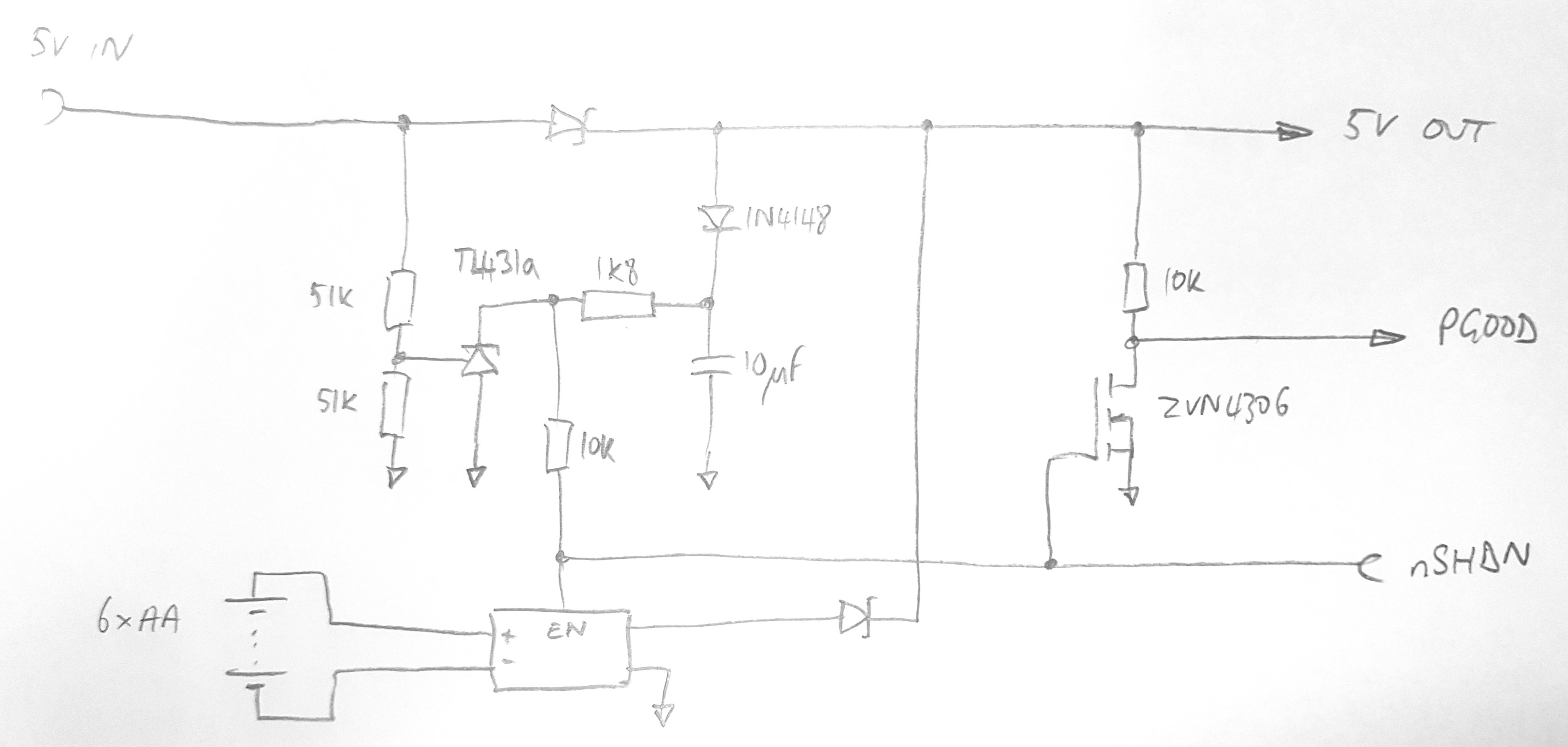
After some inspiration, and a lot of simulation in LTSpice, I've come up with this:
![]()
The idea is the battery is normally disconnected from the load until the main supply drops below about 4.8V. When this happens, the TL413a goes hi-Z making the nPGOOD line go high. This simultaneously switches the PMOS on, applying battery power, and also notifies the RPi (via a GPIO) that the power has been lost. It can then set about shutting down cleanly. The last thing it must do is change the GPIO pin from input to output, and drive it low. This cuts the battery power, turning the RPi off completely. Upon restoration of the main supply, the whole thing pops back into life, and the RPi boots as normal.
Hope it works!