Close
0%
0%

Arduino controlled photogrammetry 3D-scanner

A completely automated way to take photo's and convert them into a 3D-object

Similar projects worth following
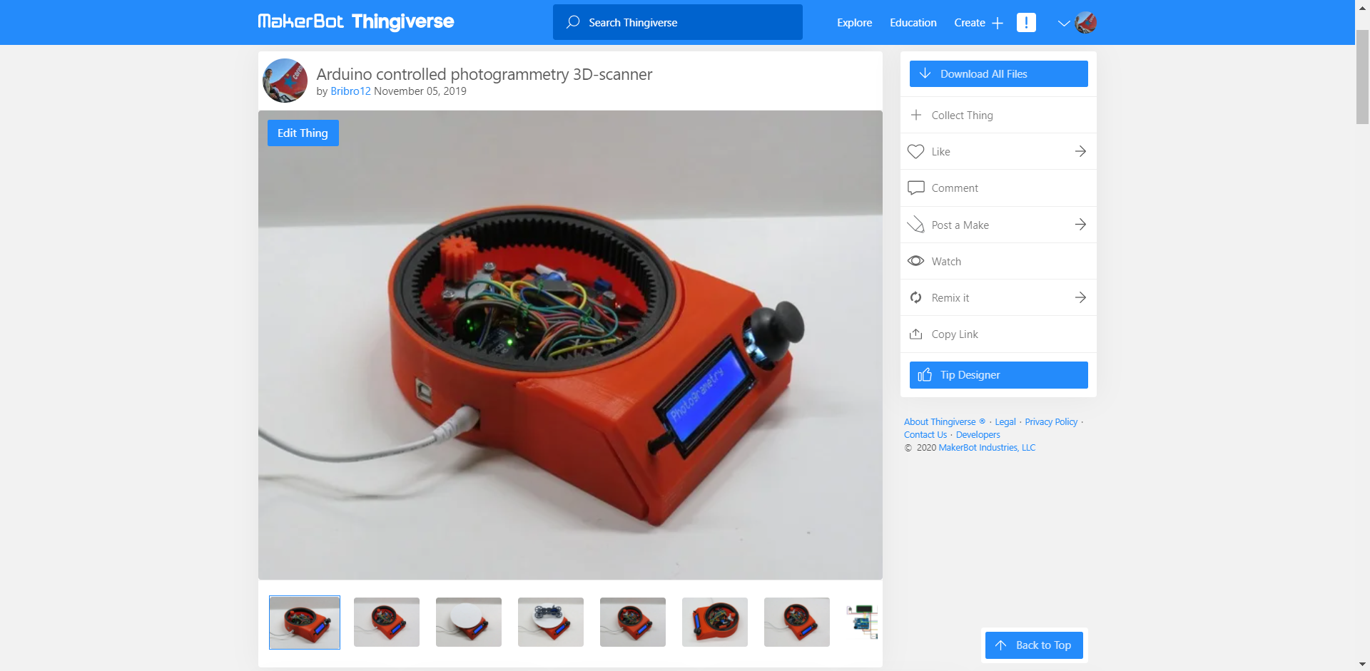
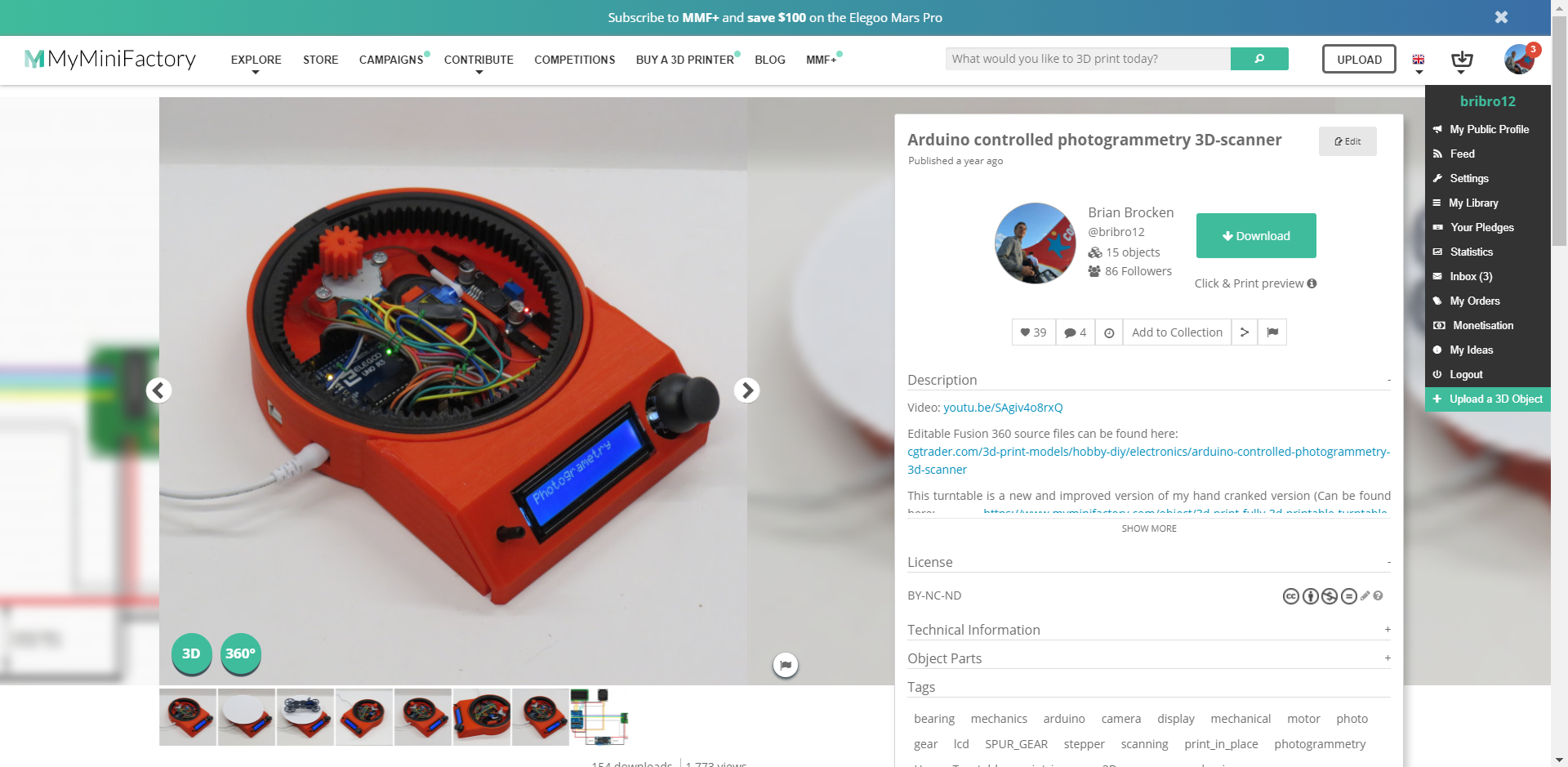
This turntable is a new and improved version of my hand cranked version (which is fully 3D-prinable, no extra parts needed. Check it out here: https://hackaday.io/project/166323-fully-3d-printable-turntable).It uses an Arduino UNO to control a 1602 LCD screen, a stepper motor and a 9g servo motor. The turntable can be used as a 3D-scanner by taking photos of an object 360 degrees around it. These photos can be converted later on into a 3D-model using photogrammetry software. The amount of photos that have to be taken can be determined by the user, ranging from 2 photos to 200 photo's (can be easily adjusted in the arduino program). The turntable can also be used to take cinematic shots. In this mode the turntable rotates at a constant speed chosen by the user. The last menu enables the user to manually move the turntable.

As said before this turntable is a new and improved version of my hand cranked version. A lot of people suggested to me I should put a stepper motor onto it to get some very nice cinematic shots. This is exactly what I did.

I gave it a bit more functionality than just a regular cinematic turntable. I added the possibility to use the turntable to capture photos 360 degrees around an object.

The photos are being taken by a smartphone connected to a Bluetooth remote located inside the turntable. I just used the most straight forward, obvious and simple solution to capture these photos, which was to use a servo to press a button on a Bluetooth remote. I went for this solution due to the fact that Apple products tend to not like the HC-05 and HC-06 Bluetooth modules and refuse to connect to them. I’m sure a cleaner and more durable solution is to use these HC-05 or HC-06 modules and connect them to an android device.

The amount of photo's that have to be taken can be determined by the user, ranging from 2 photo's to 200 photo's. These values can be easily adjusted in the Arduino program. The taken photos can be converted later on into a 3D-model using photogrammetry software. The photogrammetry software I use is Autodesk Recap Photo.

In the second menu you can find the possibility to use the turntable to make awesome cinematic shots of your objects. In this mode the turntable rotates a certain amount of turns at a constant speed chosen by the user ranging from 1 to 17 RPM (speed of the stepper motor).

The third and last menu enables the user to manually control the turntable and bring the plate to the desired position at the preferred speed.

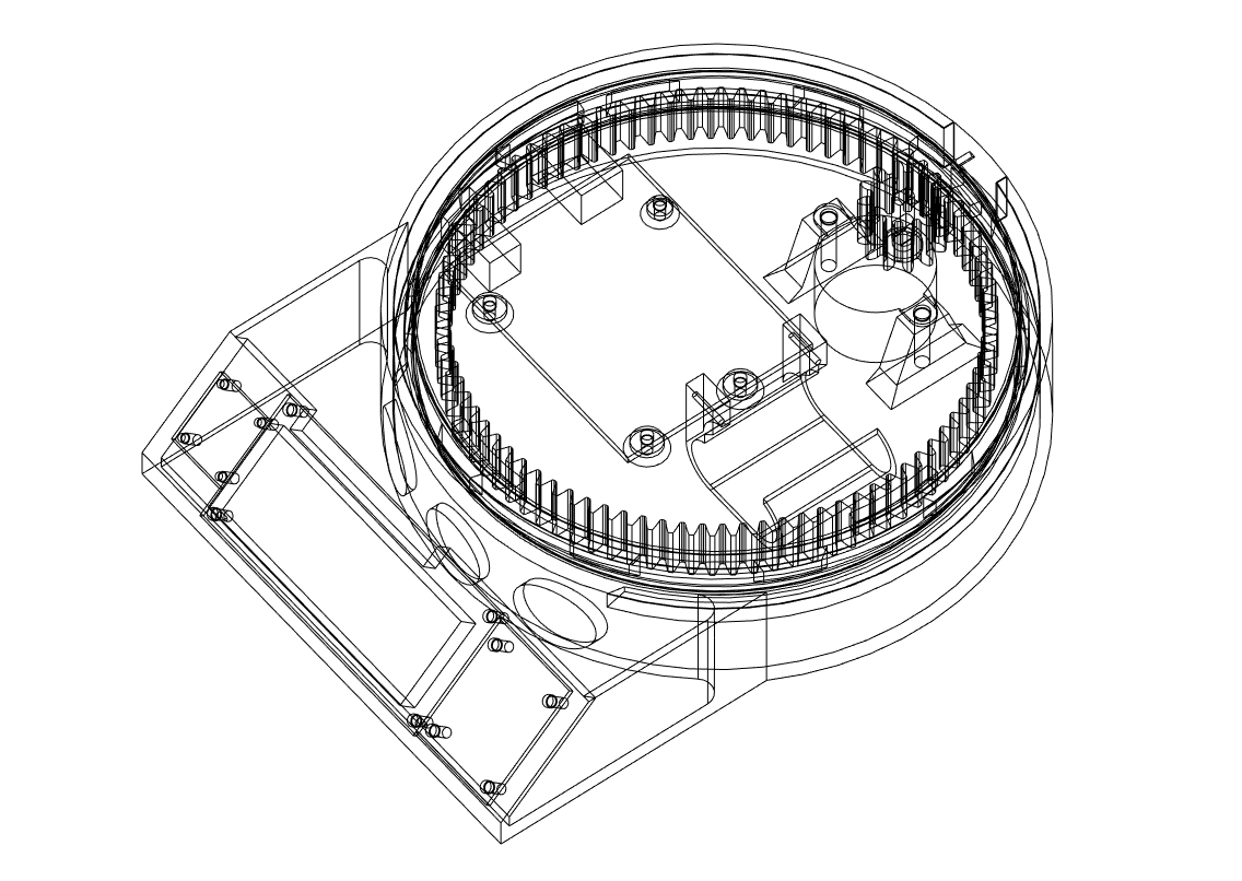
All the mechanical parts of this turntable are completely 3D-printed. The bearing for example is a print-in-place one which works great for this application. The print in place of moving objects adds to the simplicity of the build.

The reason I didn't connect the servo and stepper motor to the onboard 5V regulator and used an extra buck converter is because the stepper motor and servo draw to much current. Everytime the stepper motor rotated or stopped, the backlight in the LCD got brighter and dimmer due to the fluctuation in voltage. Using an extra buck converter takes the load from the 5 volt onboard regulator.

STL and Fusion 360 source files can be found here: https://bbprojects.technology/collections/stl-fusion-360-source-files/products/arduino-controlled-photogrammetry-3d-scanner-files

Video can be found here:

Camera_Turntable_Arduino_expansion_Final_version_1.ino

The original Arduino program for the turntable. It works but keep in mind there is room for improvement.

ino - 12.15 kB - 11/05/2019 at 21:02

Download

Code_contribution_from_Ryan_Hashiro.ino

The original code for the turntable but modified by Ryan Hashiro: 1. Added library calls and setups for an LCD with I2C backpack. 2. Added fast value change routines for the number of photogrammetry pics, motor speed, and cinematic turns. Holding joystick deflection for > 1 sec enters fast change mode. Change rate is proportional to amount of deflection. For the motor speed change is fixed at the slow speed since there's only 17 values to go through. 3. Added cancel routines for the photogrammetry and cinematic modes. Holding the joystick button down for > 2 sec kicks you out of the operation modes.

ino - 22.90 kB - 08/25/2020 at 21:02

Download

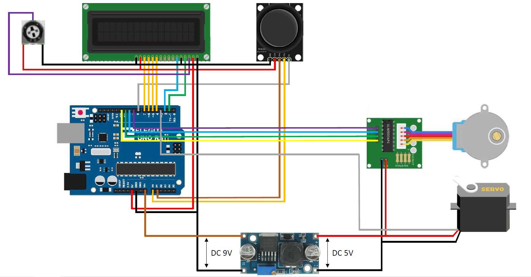
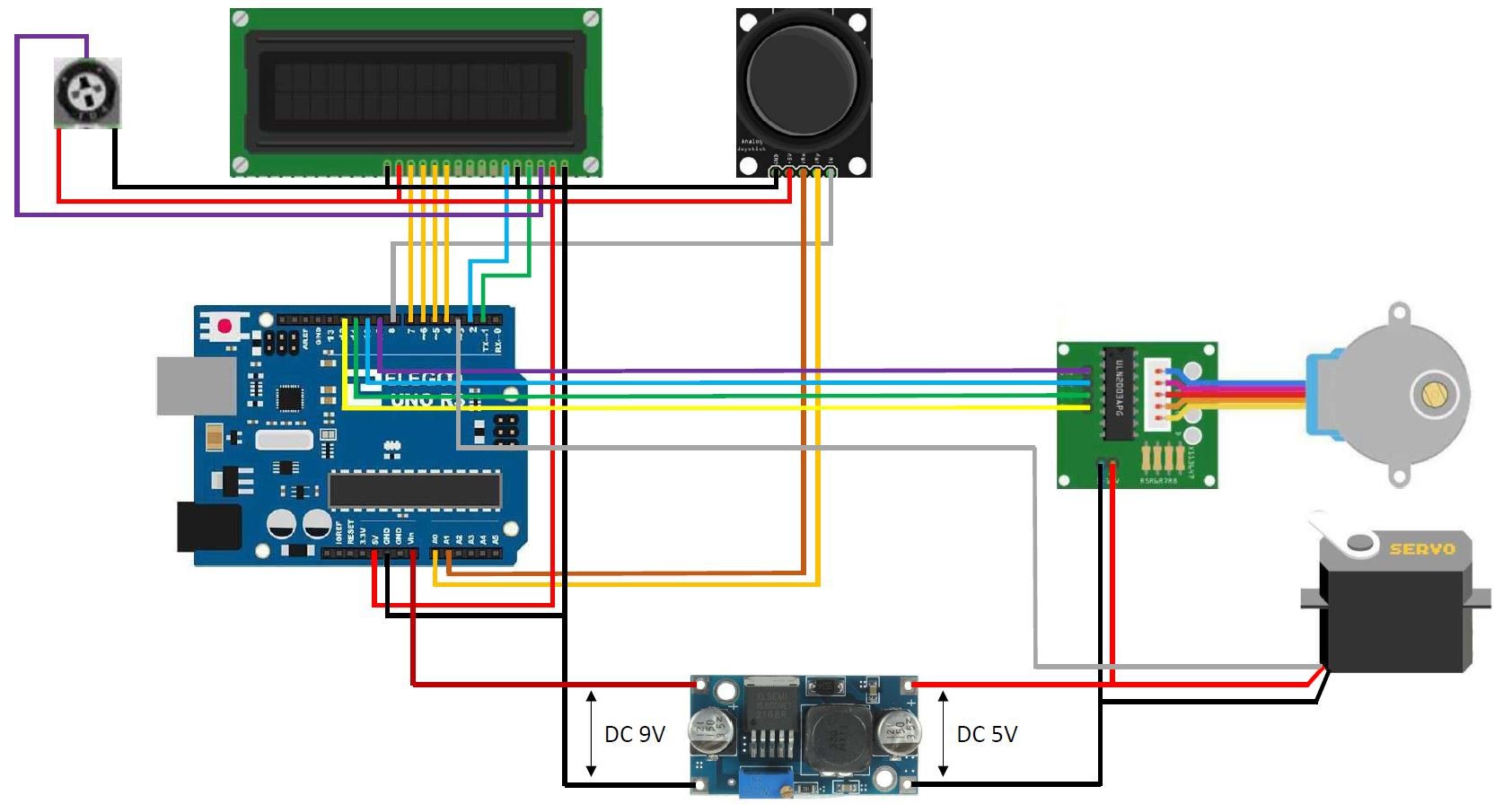
wiring diagram arduino controlled turntable V2.1.jpg

Wiring diagram for the turntable

JPEG Image - 175.86 kB - 11/24/2019 at 20:18

Preview

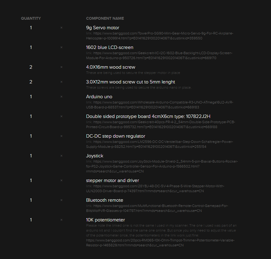
View all 11 components

  • Posted the stl-files also on Thingiverse

    Brian Brocken10/04/2020 at 22:42 0 comments
  • Posted the STL-files on MyMiniFactory

    Brian Brocken10/04/2020 at 22:40 0 comments
  • Parts list is now complete

    Brian Brocken10/04/2020 at 22:34 0 comments

    The links in the parts list have been updated and the list is now complete.

  • Posted the Fusion 360 source files on CGtrader

    Brian Brocken09/20/2020 at 19:41 0 comments

    I posted the original Fusion 360 source files on CGtrader for the people who want to tweek the design a bit.

    link: https://www.cgtrader.com/3d-print-models/hobby-diy/electronics/arduino-controlled-photogrammetry-3d-scanner

  • Added a code contribution from Ryan Hashiro to the files section

    Brian Brocken09/20/2020 at 19:37 0 comments

    Added a code contribution from Ryan Hashiro to the files section on this page.

    Code:

    /*
    
      Original code By Brian Brocken
      Contribution By Ryan Hashiro: 
      1. Added library calls and setups for an LCD with I2C backpack.
      2. Added fast value change routines for the number of photogrammetry pics, motor speed, and cinematic turns.  Holding joystick deflection for > 1 sec enters fast change mode.  Change rate is proportional to amount of deflection.  For the motor speed change is fixed at the slow speed since there's only 17 values to go through.
      3. Added cancel routines for the photogrammetry and cinematic modes.  Holding the joystick button down for > 2 sec kicks you out of the operation modes.
    
    */
    
    // #include <LiquidCrystal.h>  // use this library for the standard (non I2C) LCD
    #include <LiquidCrystal_I2C.h>  // RH - use this library for LCD displays with I2C backpack
    #include <Wire.h>  // RH - needed for the LCD I2C library.  SCL connects to pin A5.  SDA connects to pin A4.  Jumper the LED backlight pin on the I2C board
    #include <Stepper.h>
    #include <Servo.h>
    
    // LiquidCrystal lcd(1, 2, 4, 5, 6, 7);  // Use these pins for the 1602 lcd
    LiquidCrystal_I2C lcd(0x27, 16, 2);  // RH - use this for I2C LCD.  Assumes default address of 0x27
    
    const int SW_pin = 8; // digital pin connected to switch output
    const int X_pin = A0; // analog pin connected to X output
    const int Y_pin = A1; // analog pin connected to Y output
    
    int MenuNr = 0;   // Menu number
    int PhotoNr = 2;  // The amount of photos that have to be taken
    bool Flag1 = 0;   // This flag is only active during 1 program cycle (prevents constantly adding/subtracting 1 to the menu number when the joystick is pushed to the side) 
    bool Flag2 = 0;   // This flag is only active during 1 program cycle (prevents constantly adding/subtracting 2 to the photo number when the joystick is pushed up or down)
    bool Flag3 = 0;   // This flag is only active during 1 program cycle (prevents constantly adding/subtracting 1 to the RPM when the joystick is pushed up or down)
    bool Flag4 = 0;   // This flag is only active during 1 program cycle (prevents constantly adding/subtracting 1 to the turn number when the joystick is pushed to the side)
    bool Flag5 = 0;   // This flag is only active during 1 program cycle (prevents constantly adding/subtracting 1 to the RPM when the joystick is pushed up or down)
    bool Flag6 = 0;   // This flag is only active during 1 program cycle to clear the lcd
    int SwMenu = 0;   // Switch menu (Sub menu's in the main menu's)
    bool BtnFlag = 0; // This flag is only active during 1 program cycle (prevents constantly adding of 1 to SwMenu when button is pressed)
    
    // RH - added variables for fast change & cancel modes
    int FastChng = 0;  // indicates fast change value mode.  0 = off, 1 = delay mode, 2 = fast changing mode
    const unsigned long FastDelay = 1000;  // delay mode time (before values change fast)
    const unsigned long ShortInt = 100;  // short fast change interval
    const unsigned long LongInt = 300;  // long fast change interval
    const unsigned long BtnDelay = 2000;  // delay for button press to cancel operations.  Note this is an approximate delay, since stepper motor
                                         // suspends all program execution until motor finishes its move
    unsigned long SetTime = 0; // time value for fast change & button cancel modes.  Used to calculate time intervals
    bool BtnCancelFlag = 0; // This flag is used to detect when button is pressed for canceling operations
    bool MaxSwMenu = 0;  // This flag is used for detecting when the maximum SwMenu is reached
    bool CinCancelFlag = 0;  // This flag is used to trigger cinematic cancel.  1 = cancel cinematic operation
    int StepPoll = 480;  // number of motor steps to poll for cinematic cancel (at 15 rpm)
    int Cntr = 0;  // step counter for cinematic motor cancel
    // RH - end of added variables
    
    const int stepsPerRevolution = 2048;  // change this to fit the number of steps per revolution
    int FullRev = 14336;                  // 1 full revolution of the big gear -> Small-Big gear ratio is 7:1
    int rolePerMinute = 15;...
    Read more »

  • Added a youtube video to the details section of this page

    Brian Brocken09/20/2020 at 19:34 0 comments

  • Voltage Distributor

    Brian Brocken04/23/2020 at 09:44 0 comments

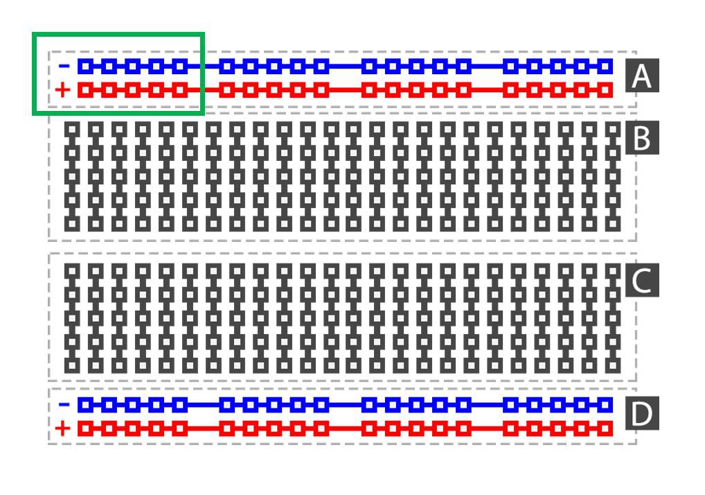
    At around 3:15 in the video () you can see I'm installing a little part next to the Arduino Uno. This is a homemade voltage distributor. It's sole purpose is to distribute 5V and 0V to other components. I made it using some double sided prototype board and soldering some 2.54mm female header pins on it. All the 5V pins are soldered together and all the 0V pins are soldered together, just like the + and - strips on a breadbord (see green box on picture below). Hope this cleared it out for some people.

    Double sided prototype boards: https://www.banggood.com/Geekcreit-40pcs-FR-4-2_54mm-Double-Side-Prototype-PCB-Printed-Circuit-Board-p-995732.html?p=E01411629100201406T1&custlinkid=669188
    2.54mm female header pins: https://www.banggood.com/10pcs-40Pin-2_54mm-Female-Header-Connector-Socket-For-DIY-Arduino-p-945516.html?rmmds=search&cur_warehouse=CN

  • Updated wiring diagram

    Brian Brocken11/24/2019 at 20:17 0 comments

    Made a very small adjustment in the wiring diagram to avoid possible confusion with the 5V and Vin pin. I changed the color of the Vin wire to orange, the 5V and Vin wire should not be connected together. The 5V wire goes up to the LCD,  joystick and potentiometer. The Vin wire goes to the DC-DC step down voltage regulator.

  • Arduino code added to the files section

    Brian Brocken11/06/2019 at 11:54 0 comments

  • Added a wiring diagram to the files section

    Brian Brocken11/05/2019 at 21:05 0 comments

View all 10 project logs

  • 1
    Step 1

View all instructions

Enjoy this project?

Share

Discussions

Hexastorm wrote 11/10/2019 at 09:40 point

Thanks for sharing this! Could you do some measurements on the accuracy of your stage.
The most familiar stage I am aware of are the heavy duty rotation stages of thorlabs see https://www.thorlabs.com/newgrouppage9.cfm?objectgroup_id=1064 . They costs like 2500 euro.
Could you share the accuracy and bidirectional repeatability. I understand you can't reach the specifications of thorlabs but it would still be interesting to know what you can achieve with this setup. Personally, i also think arduino is non sensical. The only thing what is important is the motor and stepper or servo driver you use. I would use a nema 17 motor and at at least something like TMC2130 or TMC2160.
Design looks real nice!

  Are you sure? yes | no

Brian Brocken wrote 11/10/2019 at 11:34 point

Hello, I did some quick calculating for you to get a rough idea on the accuracy. The stepper motor used takes 2048 steps to get one full rotation. The gear ratio between the small gear and larger inner gear is 1:7. So the larger inner gear needs 14336 steps to get one full rotation. One step would then rotate the larger inner gear by 0.025 degrees. 0.025 would equal about 436 µRad. This is a purely theoretical calculation, please keep in mind the bearing has a play of about 1 to 2 millimeters and there's also some play between small and larger inner gear. I really wouldn't know how to measure or calculate the bidirectional repeatability, I also don't think I have the right equipment for this. I wouldn't recommend to use this as servo or something similar as the 3D-printed bearing has to much axial and radial play. It's more then perfect for the turntable but not for a servo. If I where you, I would consider using some real bearings and create a custom design for your application. I think the right combination of 3D-printed parts and some real bearings could give you some good accuracy and repeatability. Of course not as good as a completely mechined one, but close enough 😜👍

  Are you sure? yes | no

Florian Festi wrote 11/25/2019 at 14:19 point

Repeat-ability can be tested easily by putting a mirror upright on the table and shining a laser pointer onto it. Then approach the same position from both directions and measure the difference in angle. Divide the angle by two for the actual value as the mirror doubles it. But I doubt that kind of measurement makes a lot of sense for the intended use cases. This table is clearly not suitable for machining 

  Are you sure? yes | no

Arye wrote 11/08/2019 at 17:11 point

I wonder how many kg's this pretty thing can hold being printed with pla. The latest cylinder structure seems quite solid.

  Are you sure? yes | no

Brian Brocken wrote 11/09/2019 at 09:44 point

Hello Arye, it obviously isn’t intended for larger objects (they wouldn’t fit on the plate either) but more for smaller objects like action figures, small 3D-prints,... However, all the objects i put on the table so far didn’t seem to cause any problems. The servo i put on it is quite substantial and was about the max size of the plate and it worked great😁👍 I also forgot to mention in the details I added some fine machine oil to the bearing to get rid of the friction which seems to work very well 👌😁

  Are you sure? yes | no

Brian Brocken wrote 11/09/2019 at 09:45 point

I wouldn’t go over a kilo though 😬😁👍

  Are you sure? yes | no

Brian Brocken wrote 11/09/2019 at 09:48 point

The strength of the PLA isn’t going the cause any problems in this project, the strength of the stepper motor is 😅

  Are you sure? yes | no

Dan Maloney wrote 11/06/2019 at 16:04 point

Nice build! In the video, the servo had me confused at first - I thought it was somehow locking the turntable for each shot. Then I saw the Bluetooth remote - clever! I've got a build I need to do that requires button-pushing like that - thanks for the idea.

  Are you sure? yes | no

Brian Brocken wrote 11/06/2019 at 19:17 point

Thank you Dan! I would've preferred to use a less mechanical sollution to take the photos, but Apple product just don't like to connect with bluetooth modules like the HC-05 and HC-06. My first idea was to open the bluetooth remote up and extend the contacts of the pushbutton to the arduino, but the pushbutton turned out to be a capacitive or magnetic one like the ones you can find on calculators or keyboards. So the servo pushing the button turned out to be the easiest most straight forward sollution, I mean if it works, why not haha ;-)

  Are you sure? yes | no

Tom Nardi wrote 11/06/2019 at 16:04 point

Awesome to see the design evolve. Would have been interesting to have it use the same bearing as the manually cranked one so it would be an easier/faster upgrade, but the final product definitely looks better without having the circular mounts for the legs and crank on the sides.

  Are you sure? yes | no

Brian Brocken wrote 11/06/2019 at 19:10 point

Thanks Tom! Yes i also would've liked to keep the same bearing as the hand cranked one but I had to change to much to the design in order to place all the electronics and motor etc inside it. And like you say the circular leg holders were in the way and I had to delete them. The plan was to just add a motor to it, turned out to become a completely different design haha ;-)

  Are you sure? yes | no

Similar Projects

Does this project spark your interest?

Become a member to follow this project and never miss any updates