Close
0%
0%

Arduino controlled photogrammetry 3D-scanner

A completely automated way to take photo's and convert them into a 3D-object

Similar projects worth following
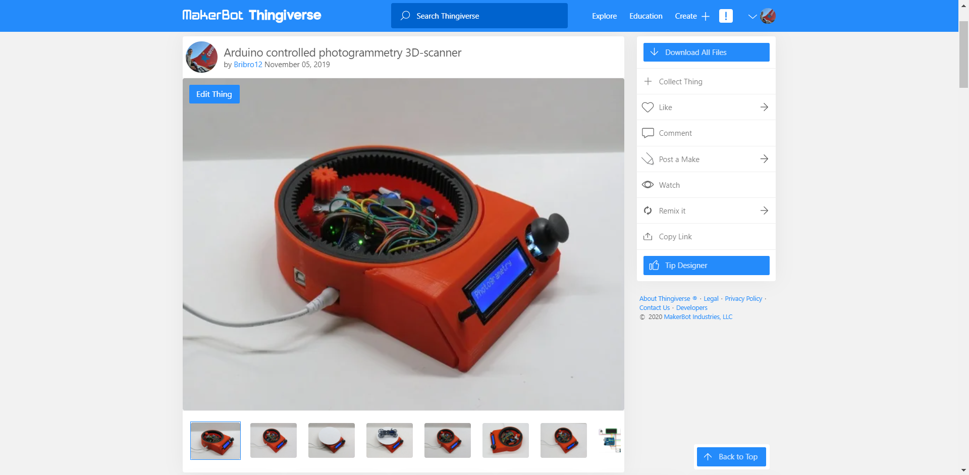
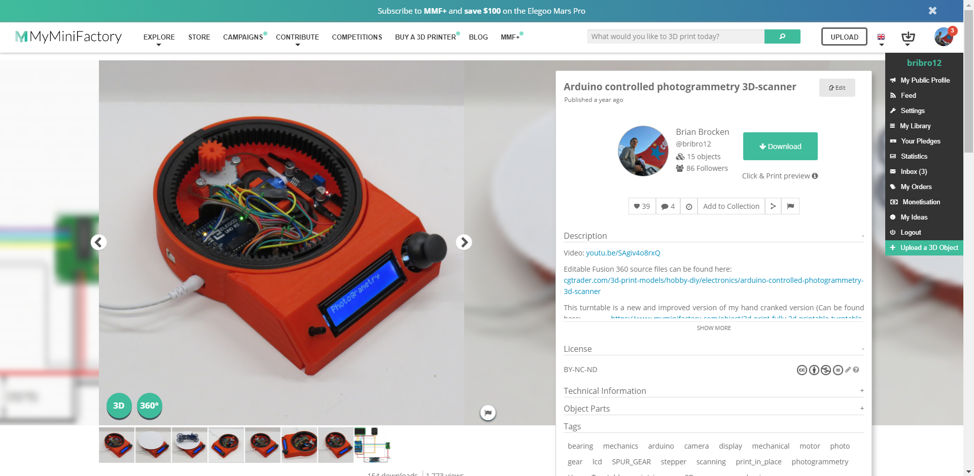
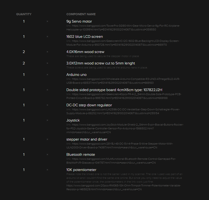
This turntable is a new and improved version of my hand cranked version (which is fully 3D-prinable, no extra parts needed. Check it out here: https://hackaday.io/project/166323-fully-3d-printable-turntable).It uses an Arduino UNO to control a 1602 LCD screen, a stepper motor and a 9g servo motor. The turntable can be used as a 3D-scanner by taking photos of an object 360 degrees around it. These photos can be converted later on into a 3D-model using photogrammetry software. The amount of photos that have to be taken can be determined by the user, ranging from 2 photos to 200 photo's (can be easily adjusted in the arduino program). The turntable can also be used to take cinematic shots. In this mode the turntable rotates at a constant speed chosen by the user. The last menu enables the user to manually move the turntable.

As said before this turntable is a new and improved version of my hand cranked version. A lot of people suggested to me I should put a stepper motor onto it to get some very nice cinematic shots. This is exactly what I did.

I gave it a bit more functionality than just a regular cinematic turntable. I added the possibility to use the turntable to capture photos 360 degrees around an object.

The photos are being taken by a smartphone connected to a Bluetooth remote located inside the turntable. I just used the most straight forward, obvious and simple solution to capture these photos, which was to use a servo to press a button on a Bluetooth remote. I went for this solution due to the fact that Apple products tend to not like the HC-05 and HC-06 Bluetooth modules and refuse to connect to them. I’m sure a cleaner and more durable solution is to use these HC-05 or HC-06 modules and connect them to an android device.

The amount of photo's that have to be taken can be determined by the user, ranging from 2 photo's to 200 photo's. These values can be easily adjusted in the Arduino program. The taken photos can be converted later on into a 3D-model using photogrammetry software. The photogrammetry software I use is Autodesk Recap Photo.

In the second menu you can find the possibility to use the turntable to make awesome cinematic shots of your objects. In this mode the turntable rotates a certain amount of turns at a constant speed chosen by the user ranging from 1 to 17 RPM (speed of the stepper motor).

The third and last menu enables the user to manually control the turntable and bring the plate to the desired position at the preferred speed.

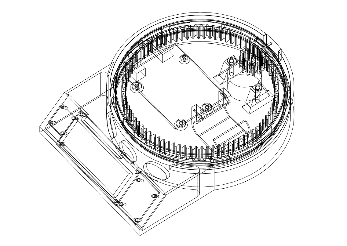
All the mechanical parts of this turntable are completely 3D-printed. The bearing for example is a print-in-place one which works great for this application. The print in place of moving objects adds to the simplicity of the build.

The reason I didn't connect the servo and stepper motor to the onboard 5V regulator and used an extra buck converter is because the stepper motor and servo draw to much current. Everytime the stepper motor rotated or stopped, the backlight in the LCD got brighter and dimmer due to the fluctuation in voltage. Using an extra buck converter takes the load from the 5 volt onboard regulator.

STL and Fusion 360 source files can be found here: https://bbprojects.technology/collections/stl-fusion-360-source-files/products/arduino-controlled-photogrammetry-3d-scanner-files

Video can be found here:

Camera_Turntable_Arduino_expansion_Final_version_1.ino

The original Arduino program for the turntable. It works but keep in mind there is room for improvement.

ino - 12.15 kB - 11/05/2019 at 21:02

Download

Code_contribution_from_Ryan_Hashiro.ino

The original code for the turntable but modified by Ryan Hashiro: 1. Added library calls and setups for an LCD with I2C backpack. 2. Added fast value change routines for the number of photogrammetry pics, motor speed, and cinematic turns. Holding joystick deflection for > 1 sec enters fast change mode. Change rate is proportional to amount of deflection. For the motor speed change is fixed at the slow speed since there's only 17 values to go through. 3. Added cancel routines for the photogrammetry and cinematic modes. Holding the joystick button down for > 2 sec kicks you out of the operation modes.

ino - 22.90 kB - 08/25/2020 at 21:02

Download

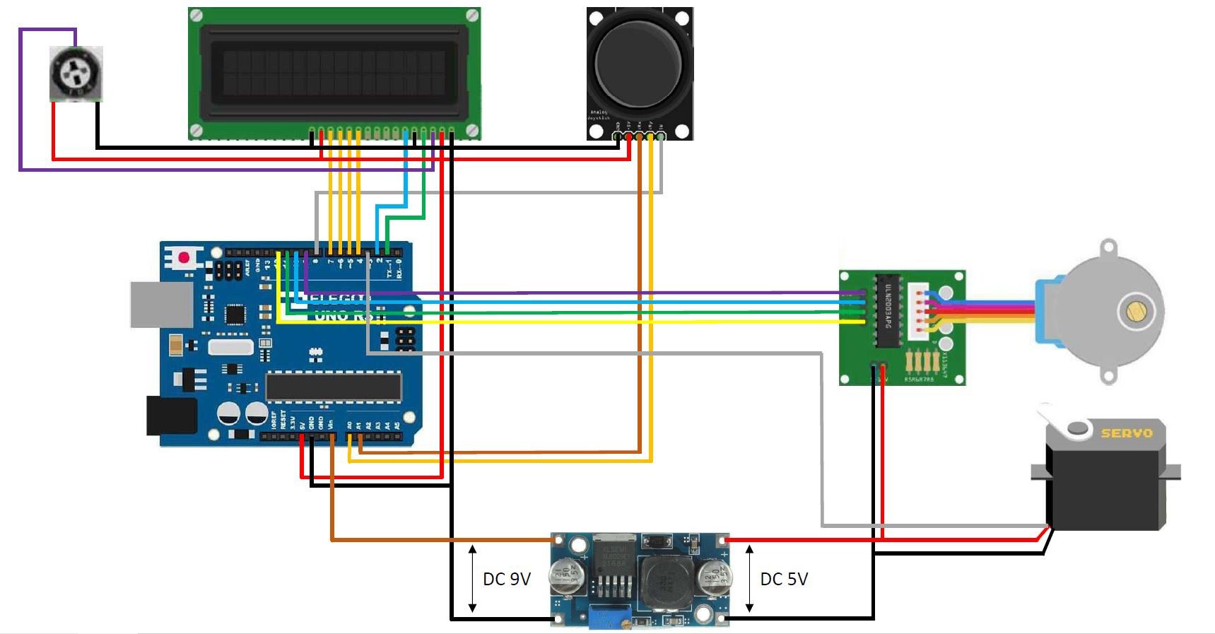
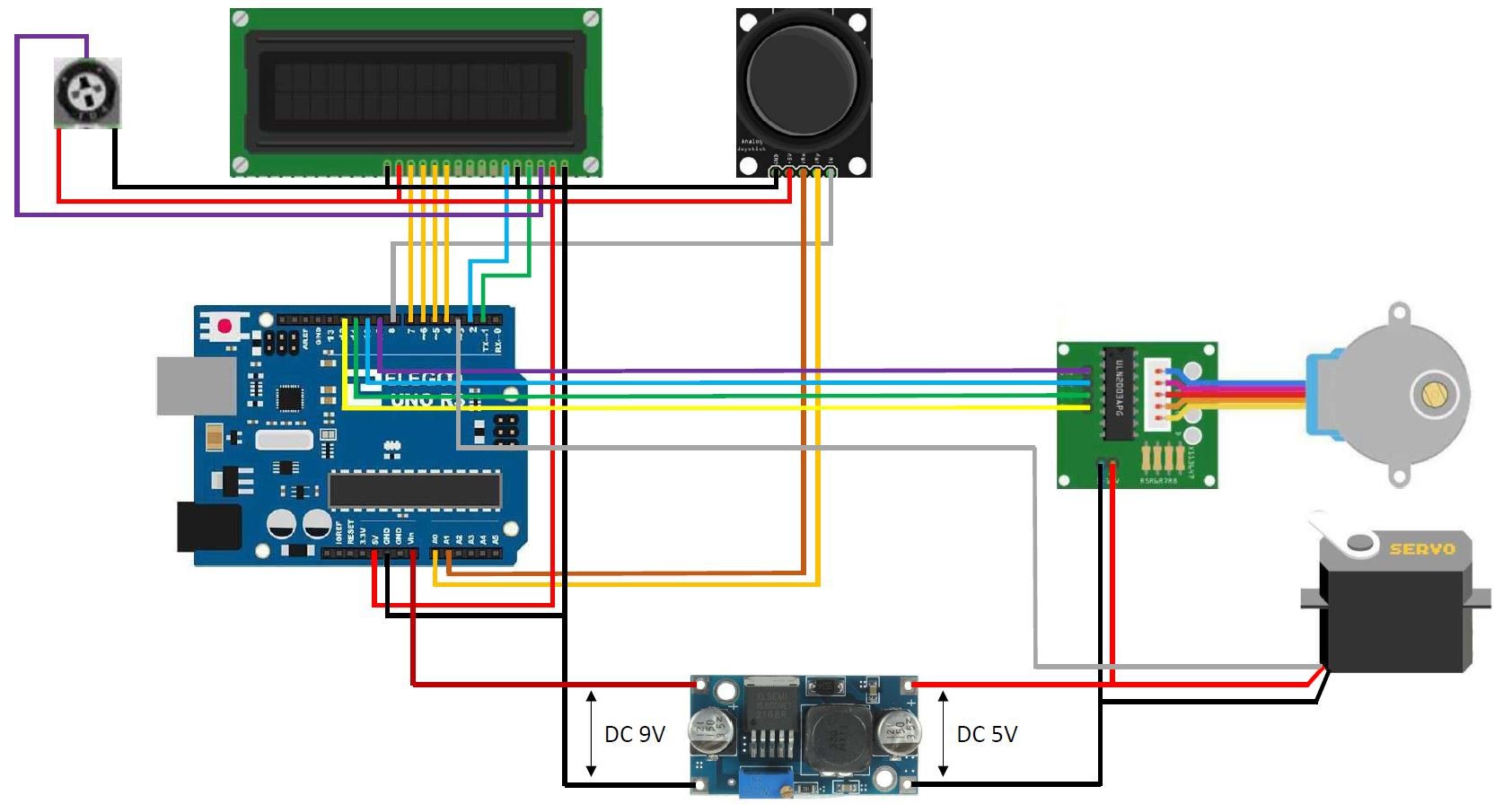
wiring diagram arduino controlled turntable V2.1.jpg

Wiring diagram for the turntable

JPEG Image - 175.86 kB - 11/24/2019 at 20:18

Preview

View all 11 components

  • Posted the stl-files also on Thingiverse

    Brian Brocken10/04/2020 at 22:42 0 comments
  • Posted the STL-files on MyMiniFactory

    Brian Brocken10/04/2020 at 22:40 0 comments
  • Parts list is now complete

    Brian Brocken10/04/2020 at 22:34 0 comments

    The links in the parts list have been updated and the list is now complete.

  • Posted the Fusion 360 source files on CGtrader

    Brian Brocken09/20/2020 at 19:41 0 comments

    I posted the original Fusion 360 source files on CGtrader for the people who want to tweek the design a bit.

    link: https://www.cgtrader.com/3d-print-models/hobby-diy/electronics/arduino-controlled-photogrammetry-3d-scanner

  • Added a code contribution from Ryan Hashiro to the files section

    Brian Brocken09/20/2020 at 19:37 0 comments

    Added a code contribution from Ryan Hashiro to the files section on this page.

    Code:

    /*
    
      Original code By Brian Brocken
      Contribution By Ryan Hashiro: 
      1. Added library calls and setups for an LCD with I2C backpack.
      2. Added fast value change routines for the number of photogrammetry pics, motor speed, and cinematic turns.  Holding joystick deflection for > 1 sec enters fast change mode.  Change rate is proportional to amount of deflection.  For the motor speed change is fixed at the slow speed since there's only 17 values to go through.
      3. Added cancel routines for the photogrammetry and cinematic modes.  Holding the joystick button down for > 2 sec kicks you out of the operation modes.
    
    */
    
    // #include <LiquidCrystal.h>  // use this library for the standard (non I2C) LCD
    #include <LiquidCrystal_I2C.h>  // RH - use this library for LCD displays with I2C backpack
    #include <Wire.h>  // RH - needed for the LCD I2C library.  SCL connects to pin A5.  SDA connects to pin A4.  Jumper the LED backlight pin on the I2C board
    #include <Stepper.h>
    #include <Servo.h>
    
    // LiquidCrystal lcd(1, 2, 4, 5, 6, 7);  // Use these pins for the 1602 lcd
    LiquidCrystal_I2C lcd(0x27, 16, 2);  // RH - use this for I2C LCD.  Assumes default address of 0x27
    
    const int SW_pin = 8; // digital pin connected to switch output
    const int X_pin = A0; // analog pin connected to X output
    const int Y_pin = A1; // analog pin connected to Y output
    
    int MenuNr = 0;   // Menu number
    int PhotoNr = 2;  // The amount of photos that have to be taken
    bool Flag1 = 0;   // This flag is only active during 1 program cycle (prevents constantly adding/subtracting 1 to the menu number when the joystick is pushed to the side) 
    bool Flag2 = 0;   // This flag is only active during 1 program cycle (prevents constantly adding/subtracting 2 to the photo number when the joystick is pushed up or down)
    bool Flag3 = 0;   // This flag is only active during 1 program cycle (prevents constantly adding/subtracting 1 to the RPM when the joystick is pushed up or down)
    bool Flag4 = 0;   // This flag is only active during 1 program cycle (prevents constantly adding/subtracting 1 to the turn number when the joystick is pushed to the side)
    bool Flag5 = 0;   // This flag is only active during 1 program cycle (prevents constantly adding/subtracting 1 to the RPM when the joystick is pushed up or down)
    bool Flag6 = 0;   // This flag is only active during 1 program cycle to clear the lcd
    int SwMenu = 0;   // Switch menu (Sub menu's in the main menu's)
    bool BtnFlag = 0; // This flag is only active during 1 program cycle (prevents constantly adding of 1 to SwMenu when button is pressed)
    
    // RH - added variables for fast change & cancel modes
    int FastChng = 0;  // indicates fast change value mode.  0 = off, 1 = delay mode, 2 = fast changing mode
    const unsigned long FastDelay = 1000;  // delay mode time (before values change fast)
    const unsigned long ShortInt = 100;  // short fast change interval
    const unsigned long LongInt = 300;  // long fast change interval
    const unsigned long BtnDelay = 2000;  // delay for button press to cancel operations.  Note this is an approximate delay, since stepper motor
                                         // suspends all program execution until motor finishes its move
    unsigned long SetTime = 0; // time value for fast change & button cancel modes.  Used to calculate time intervals
    bool BtnCancelFlag = 0; // This flag is used to detect when button is pressed for canceling operations
    bool MaxSwMenu = 0;  // This flag is used for detecting when the maximum SwMenu is reached
    bool CinCancelFlag = 0;  // This flag is used to trigger cinematic cancel.  1 = cancel cinematic operation
    int StepPoll = 480;  // number of motor steps to poll for cinematic cancel (at 15 rpm)
    int Cntr = 0;  // step counter for cinematic motor cancel
    // RH - end of added variables
    
    const int stepsPerRevolution = 2048;  // change this to fit the number of steps per revolution
    int FullRev = 14336;                  // 1 full revolution of the big gear -> Small-Big gear ratio is 7:1
    int rolePerMinute = 15;...
    Read more »

  • Added a youtube video to the details section of this page

    Brian Brocken09/20/2020 at 19:34 0 comments

  • Voltage Distributor

    Brian Brocken04/23/2020 at 09:44 0 comments

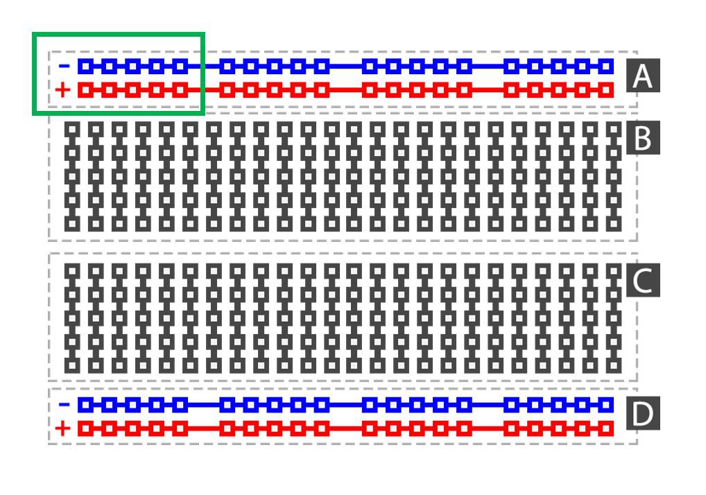
    At around 3:15 in the video () you can see I'm installing a little part next to the Arduino Uno. This is a homemade voltage distributor. It's sole purpose is to distribute 5V and 0V to other components. I made it using some double sided prototype board and soldering some 2.54mm female header pins on it. All the 5V pins are soldered together and all the 0V pins are soldered together, just like the + and - strips on a breadbord (see green box on picture below). Hope this cleared it out for some people.

    Double sided prototype boards: https://www.banggood.com/Geekcreit-40pcs-FR-4-2_54mm-Double-Side-Prototype-PCB-Printed-Circuit-Board-p-995732.html?p=E01411629100201406T1&custlinkid=669188
    2.54mm female header pins: https://www.banggood.com/10pcs-40Pin-2_54mm-Female-Header-Connector-Socket-For-DIY-Arduino-p-945516.html?rmmds=search&cur_warehouse=CN

  • Updated wiring diagram

    Brian Brocken11/24/2019 at 20:17 0 comments

    Made a very small adjustment in the wiring diagram to avoid possible confusion with the 5V and Vin pin. I changed the color of the Vin wire to orange, the 5V and Vin wire should not be connected together. The 5V wire goes up to the LCD,  joystick and potentiometer. The Vin wire goes to the DC-DC step down voltage regulator.

  • Arduino code added to the files section

    Brian Brocken11/06/2019 at 11:54 0 comments

  • Added a wiring diagram to the files section

    Brian Brocken11/05/2019 at 21:05 0 comments

View all 10 project logs

  • 1
    Step 1

View all instructions

Enjoy this project?

Share

Discussions

mannycalavera2 wrote 08/31/2020 at 02:40 point

Can this code be used with and lcd keypad shield?

  Are you sure? yes | no

tr.patrick wrote 08/19/2020 at 14:40 point

Bonjour à tous

Pouvez vous me dire comment câbler le servo moteur les couleurs de fils du servo sont orange ,rouge, marron et votre câble noir,rouge,gris comment trouve le + et le -  du servo moteur ?

  Are you sure? yes | no

arduinofiendo wrote 08/19/2020 at 00:05 point

I have everything assembled, but am having an issue with the stepper motor and servo. On the stepper motor board there are multiple pins labeled 5-12 volts. If I plug the power into the far left pin, which i am assuming is 5 volts the servo works, but not the stepper motor. If I plug the power into the far right pin the stepper works, but not the servo?!!  Any idea why this is happening?  Also the lights on the stepper motor board will not turn on unless I have the power connected to the far right pin. 

  Are you sure? yes | no

Ryan Hashiro wrote 08/19/2020 at 11:13 point

On my board (I am using the 28YBJ-48 stepper motor per the parts list), there are 4 pins at the power input, but the right 2 pins are jumpered.  I think the "5-12" is the voltage range you can apply to the board.  The far left pin is ground (there is a small "-" right next to that pin).  The next pin over (the one with the small "+") is positive voltage - that's the one you should apply the 5V to.

  Are you sure? yes | no

arduinofiendo wrote 08/25/2020 at 00:39 point

Thanks for the reply! I bought a multimeter to test the voltages as it still wasn't working. Where are you getting these 9 volts from for the buck converter? I'm reading about 4.7 volts of input. and I cant get it to output anything over 3.74 volts, no matter how much i turn the adjustment screw, I'm guessing this is why my stepper and servo won't run together? 

  Are you sure? yes | no

Ryan Hashiro wrote 12/08/2020 at 09:06 point

Sorry I have been away for awhile.  The 9V is obtained from the "Vin" pin of the Uno.  It is tied to the power input jack, so it will be at whatever voltage you feed into the power jack.  The schematic assumes you are using a 9VDC power source, but it can be whatever range the Uno can take (I think 5V to 20V).  You shouldn't go too high as the voltage regulators might overheat.  Too low and your buck converter for the servo won't have enough input level to step down to 5V.  You should figure at least 2V or so drop from input to output for the buck to work properly.  That is why your output is so low.  Hope this helps!

  Are you sure? yes | no

Ryan Hashiro wrote 07/19/2020 at 11:43 point

Wow this is a well-designed project!  I'm working on adding features to the arduino code while waiting for parts I ordered to come in.  Code additions/mods I'm working on include 1) allowing use of an I2C LCD display (the one I ordered from banggood came with an I2C backpack soldered on).  2) fast-scroll for setting the number of pics in the photogrametry mode and number of turns in the cinematic mode.  3) allowing operation cancel while in the photogrametry and cinematic operation.  I would like to share the code mods if/when I get it working - is there a way to easily do that here?

  Are you sure? yes | no

Brian Brocken wrote 07/21/2020 at 09:34 point

Hello Ryan, first of all thank you, if you want you code displayed on this page, you can send me your code and i'll put in on here and add your name to it ;-)

  Are you sure? yes | no

Ryan Hashiro wrote 07/21/2020 at 23:46 point

OK thanks - will do!  I have to wait for my stepper motor to arrive - I need to see how the cancel operation affects the motor movement.  [I discovered that the move command seems to block all program execution until the entire move execution stops - i.e. if you instruct the plate to do one full turn, program suspends until the full turn is done.   Will need to divide the plate turns into partial movements and do periodic cancel checks in between].

  Are you sure? yes | no

Brian Brocken wrote 08/25/2020 at 21:12 point

I just added your code to the files section.

  Are you sure? yes | no

Rlove1966 wrote 06/11/2020 at 08:02 point

can anyone answer this: in the wiring diagram the 5v and ground from the pot, lcd and joystick connect together before connecting to the uno... how does that work? It seems like one big wire is split up or something... much thanks in advance for help

  Are you sure? yes | no

Anacapala wrote 07/02/2020 at 03:37 point

It can be constructed in many different ways.  One version is a double row of male or female header pins soldered to a piece of prototyping PCB.  On the solder side, all the pins in each row are soldered together. The 5v supply and the common ground are then soldered to their respective rows.   Now you can plug any ground wire into a pin in the 'ground' row, and any 5v wire into a '5v' row pin. You can use the same sort of double-row piece of prototyping PCB and solder each wire to a hole for its respective row, or you could use two separate pieces of PCB, or just twist them together in two bundles and solder each group (but that is more difficult and doesn't look good).

  Are you sure? yes | no

rlove wrote 07/02/2020 at 06:01 point

so I lug in the two pins for power and then plug the rest of the stuff into the same PCs board?

  Are you sure? yes | no

Rlove1966 wrote 06/11/2020 at 02:24 point

I'm a total newb that is ready to dive in... all parts printed, wires ready... my problem is i don't understand how the power distribution module you made works. Where is the input and where are the outputs? (probably a stupid questions) I think i've got everything else down...i'm planning on using the turntable in my classroom. (and maybe build a bigger one with them too!)

  Are you sure? yes | no

rorybourdon wrote 07/02/2020 at 22:20 point

input 5v anywhere on one of the rows you soldered together, and ground on the other row... then plug everything else into the 5v or ground row as needed

  Are you sure? yes | no

Anacapala wrote 05/29/2020 at 05:45 point

Great project - works well and easy to follow instructions.   The following points might be useful for others.
- Don't stint on the power/gnd  distribution pins.  6 is the minimum - 8 is better.
- The stepper driver board can be mounted vertically using a bracket attached under the mounting screw for the motor.
- I used a 7805 on a scrap of prototyping PCB for the 5v for the motor rather than a buck converter. The IC has a hole in the tab that can be used to mount it under the other mounting screw for the motor.
- I used 90-degree male/male header pins so that all connections to the Arduino board are horizontal. This makes fitting everything much easier.  Use the type that is equal length on both ends - not the PCB mounting type which has one end much shorter than the other - and push the plastic shroud into the angle so that the full length of the pin is available for the socket.
- I got a lot of bounce from the joystick button until I changed the initialisation code for the pin for the button to
  pinMode(SW_pin, INPUT_PULLUP);      //Set pushbutton as input
  // digitalWrite(SW_pin, HIGH);      //Set SW_pin High
I think the original code might be for an earlier version of the IDE.
- Digital Pin 3 is available for driving the camera shutter release. I used a IR LED with some code I found on the www for triggering the remote shutter release on the camera, and that works well.  For instance:
https://www.christidis.info/index.php/personal-projects/arduino-nikon-infrared-command-code
- Don't try to debug the code using serial output in the IDE because it won't work ;-(

  Are you sure? yes | no

kyle wrote 05/26/2020 at 15:42 point

Hi Brian- just want to say thank you for uploading this project!


My question is probably a silly one I’m afraid but I’ve been searching everywhere and don’t seem to be able to get an answer.


regarding the 5v cable coming from the arduino board- how is the easiest way to get it connecting to the potentiometer, LCD and joystick? I’m experiencing a similar issue with the ground cable. I’ve tried playing your video frame by frame as well as googling it.


many thanks! 

  Are you sure? yes | no

Rlove1966 wrote 06/25/2020 at 04:37 point

I have the same issues...

  Are you sure? yes | no

Brian Brocken wrote 08/25/2020 at 21:10 point

I think you can find your anwer in the following log:

Voltage Distributor

  Are you sure? yes | no

damminh88 wrote 05/26/2020 at 03:09 point

Hi Brian, im i encountered blank lcd problem. please help me

  Are you sure? yes | no

Josh Smith wrote 05/19/2020 at 22:11 point

Heya! Project is going well so far except one thing, I am unable to select the next menu screen by pressing on the joystick, I should have everything wired correctly, any suggestions?

  Are you sure? yes | no

Paul wrote 05/11/2020 at 15:58 point

Hello Brian, I would like to make a few changes to the STL parts. Is it possible to get the Fusion 360 files? I would be more than willing to share the the changes of course. I understand if this is not possible.

  Are you sure? yes | no

Brian Brocken wrote 09/20/2020 at 19:44 point

  Are you sure? yes | no

David Ladd wrote 02/23/2020 at 21:31 point

Hey, this is a cool project.

Rather than using the servo on the remote had you thought about using a 2N2222 transistor and a resistor from the Arduino to act like a switch and hack the remote directly?

  Are you sure? yes | no

Michael Gardi wrote 02/16/2020 at 03:36 point

Done. Works great. Posted a make to Thingiverse.

  Are you sure? yes | no

Michael Gardi wrote 02/15/2020 at 18:38 point

Hi Brian, quick question. Is there a reason that you decided not to use the i2c or iic interface for the display? I sourced a slightly different display that doesn't have pin headers for the parallel interface.

  Are you sure? yes | no

Brian Brocken wrote 02/15/2020 at 18:43 point

Hello Michael, I build this 3D-scanner using only the parts from a sponsored kit, and that LCD, arduino UNO, etc... where the parts I had to work with so that's the reason why. The LCD with the I2C interface would work just as good but you might need to change the code and mayby also the base where the LCD is mounted on.

  Are you sure? yes | no

Michael Gardi wrote 02/15/2020 at 19:02 point

Thanks for getting back to me so fast. I was concerned it might have had something to do with the UI. I originally ordered all the parts from banggood but unfortunately they could not ship them until March 25th. So I ended up with some slight differences like the LCD. And yes I had to hack the base to get it to fit :-(.  I think I’m going to try and get the i2c interface working as well to simplify the wiring and because I haven’t done i2c in quite awhile. 

  Are you sure? yes | no

Brian Brocken wrote 02/15/2020 at 19:07 point

No problem Michael haha, You could try to get the I2C module to work, which would work just as good as the way I did it. I also saw people just cutting the pins of the module, desolder the pins and wire it the same way I did on my wiring diagram which is also a possibility.

  Are you sure? yes | no

Michael Gardi wrote 02/16/2020 at 03:45 point

Switching to i2c was easy. Wired SDA to A4 and SCL to A5 plus VCC and GND then switched to the LiquidCrystal_I2C library and everything just worked. I did directly wire V0 to the pot for brightness control. Works great!

  Are you sure? yes | no

kboruff wrote 01/27/2020 at 03:45 point

I'm new to buck converters but they seem useful. I bought the one linked, LM9526. It appears to go from whatever voltage to 1-3.5v depending on the setting. On the diagram it shows taking 9v DC and turning it into 5v DC. Since the Arduino has a 5v line, I'm confused how to implement it. When I plug it in and adjust the resistance, the light flickers and the motor vibrates, but I think it is far underpowered.

 How should it be hooked up? Did I understand the diagram correctly to separate the Servo/gear voltage and ground from the general voltage and ground? Also, this is a very nice design. I'm taking out the Servo and using an opticoupler to trigger a shutter release for a Canon.

  Are you sure? yes | no

Brian Brocken wrote 02/15/2020 at 18:50 point

Hello kboruff, sorry for the late reply, The buck converter is connected to the Vin pin on the Arduino. The Vin pin has the same voltage as the voltage of the power source that's connected to it, in this case a 9V adapter. And yes you are right, you should keep the ground and 5 volts of the servo and stepper motor seperated from the LCD and joystick, this is the reason I use the buck converter, when the stepper motor and servo are in motion they tend to take to much current from the system and the LCD starts to flicker. The buck converter solves this problem.

  Are you sure? yes | no

Michael Gardi wrote 01/26/2020 at 04:40 point

Thanks so much for sharing. Parts are printing. Components are ordered. 

  Are you sure? yes | no

Brian Brocken wrote 01/26/2020 at 11:23 point

Haha thanks Michael ;-)

  Are you sure? yes | no

saliter wrote 01/13/2020 at 19:31 point

where are you getting power?

But fascinating project.

  Are you sure? yes | no

Michael Gardi wrote 01/26/2020 at 04:15 point

I'm curious about the power as well. Why the buck converter when everything is running off 5V anyway?

  Are you sure? yes | no

Brian Brocken wrote 01/26/2020 at 11:22 point

The stepper motor and servo draw to much current to run of the oboard 5V regulator. Everytime the stepper motor rotated or stopped, the backlight in the LCD got brighter and dimmer due to the fluctuation in voltage. Using an extra buck converter takes the load from the 5 volt onboard regulator.

  Are you sure? yes | no

Rizky Zulkarnaen wrote 12/24/2019 at 20:53 point

hi, I'm planning to use esp32 as remote shutter (https://github.com/MinatsuT/esp32_remote_shutter) for smartphone and also for controlling the motor.

  Are you sure? yes | no

Kevin wrote 12/03/2019 at 17:16 point

I've been thinking of putting something together to either laser line or structured light scanning of objects. This project would be very useful towards that goal. What is the outer diameter of the main cylinder that holds the motor and gears?

  Are you sure? yes | no

jrweikle wrote 11/13/2019 at 14:58 point

what is the pot for?  and what value is it?

  Are you sure? yes | no

Brian Brocken wrote 11/13/2019 at 15:02 point

The potentiometer is there to adjust the brightness of the backlight of the lcd. I used a 10K one.

  Are you sure? yes | no

jrweikle wrote 11/13/2019 at 15:22 point

thanks i thought so but was unsure without the data sheet

  Are you sure? yes | no

Chee Kit wrote 01/24/2020 at 05:12 point

Hi the pot that you linked is different. Would that work as well? Or could you maybe link me to the one you used?

  Are you sure? yes | no

Brian Brocken wrote 01/26/2020 at 11:31 point

Hello Chee Kit, The one i used in my scanner was part of an arduino kit and I couldn't find the exact same one online. But since you only need to adjust the value of the potentiometer once (only to adjust the brightness og the LCD) the potentiometer in the link works just fine.

  Are you sure? yes | no

Similar Projects

Does this project spark your interest?

Become a member to follow this project and never miss any updates