Close
0%
0%

Arduino controlled photogrammetry 3D-scanner

A completely automated way to take photo's and convert them into a 3D-object

Similar projects worth following
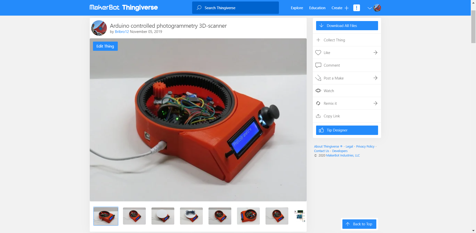
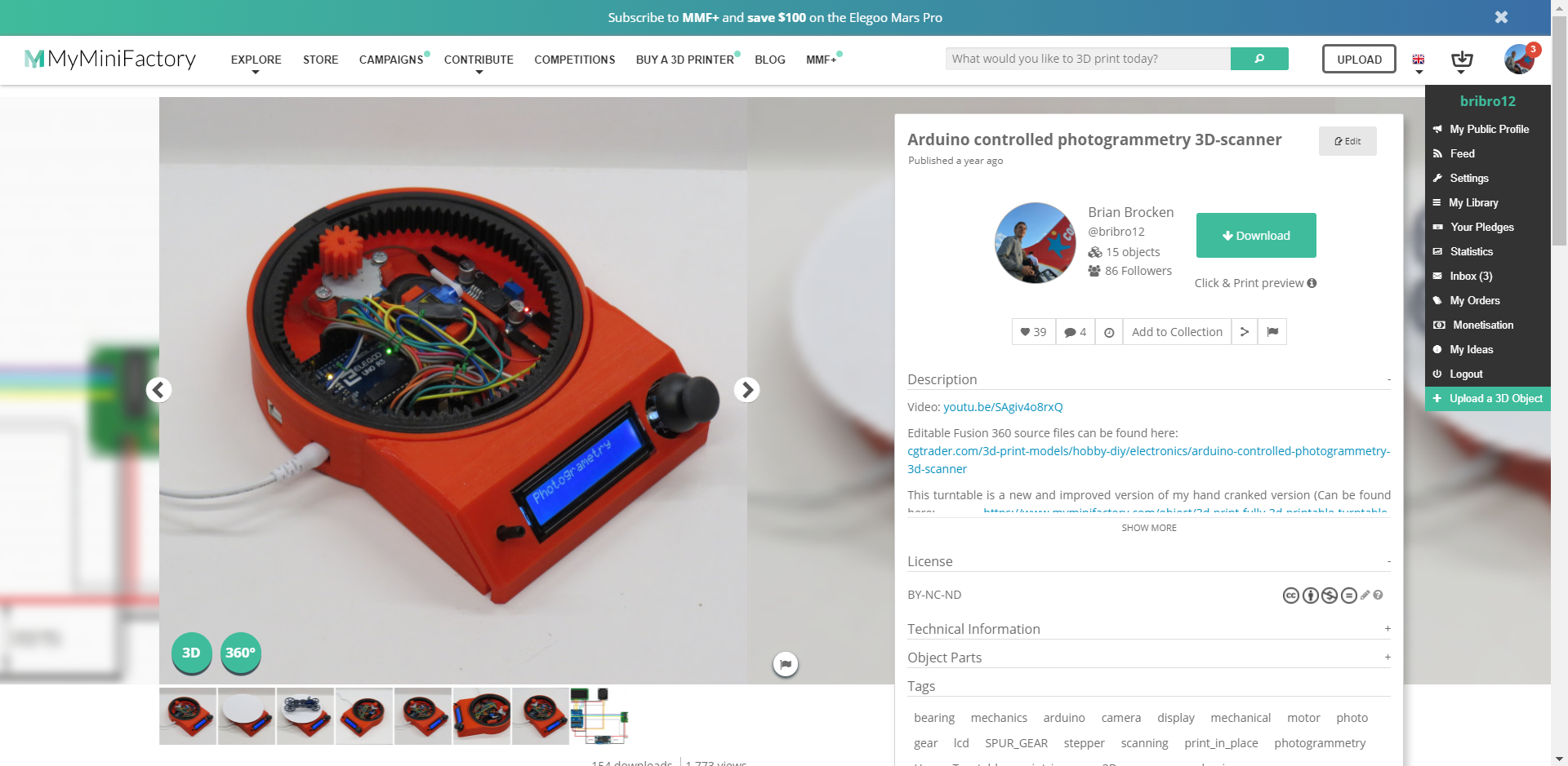
This turntable is a new and improved version of my hand cranked version (which is fully 3D-prinable, no extra parts needed. Check it out here: https://hackaday.io/project/166323-fully-3d-printable-turntable).It uses an Arduino UNO to control a 1602 LCD screen, a stepper motor and a 9g servo motor. The turntable can be used as a 3D-scanner by taking photos of an object 360 degrees around it. These photos can be converted later on into a 3D-model using photogrammetry software. The amount of photos that have to be taken can be determined by the user, ranging from 2 photos to 200 photo's (can be easily adjusted in the arduino program). The turntable can also be used to take cinematic shots. In this mode the turntable rotates at a constant speed chosen by the user. The last menu enables the user to manually move the turntable.

As said before this turntable is a new and improved version of my hand cranked version. A lot of people suggested to me I should put a stepper motor onto it to get some very nice cinematic shots. This is exactly what I did.

I gave it a bit more functionality than just a regular cinematic turntable. I added the possibility to use the turntable to capture photos 360 degrees around an object.

The photos are being taken by a smartphone connected to a Bluetooth remote located inside the turntable. I just used the most straight forward, obvious and simple solution to capture these photos, which was to use a servo to press a button on a Bluetooth remote. I went for this solution due to the fact that Apple products tend to not like the HC-05 and HC-06 Bluetooth modules and refuse to connect to them. I’m sure a cleaner and more durable solution is to use these HC-05 or HC-06 modules and connect them to an android device.

The amount of photo's that have to be taken can be determined by the user, ranging from 2 photo's to 200 photo's. These values can be easily adjusted in the Arduino program. The taken photos can be converted later on into a 3D-model using photogrammetry software. The photogrammetry software I use is Autodesk Recap Photo.

In the second menu you can find the possibility to use the turntable to make awesome cinematic shots of your objects. In this mode the turntable rotates a certain amount of turns at a constant speed chosen by the user ranging from 1 to 17 RPM (speed of the stepper motor).

The third and last menu enables the user to manually control the turntable and bring the plate to the desired position at the preferred speed.

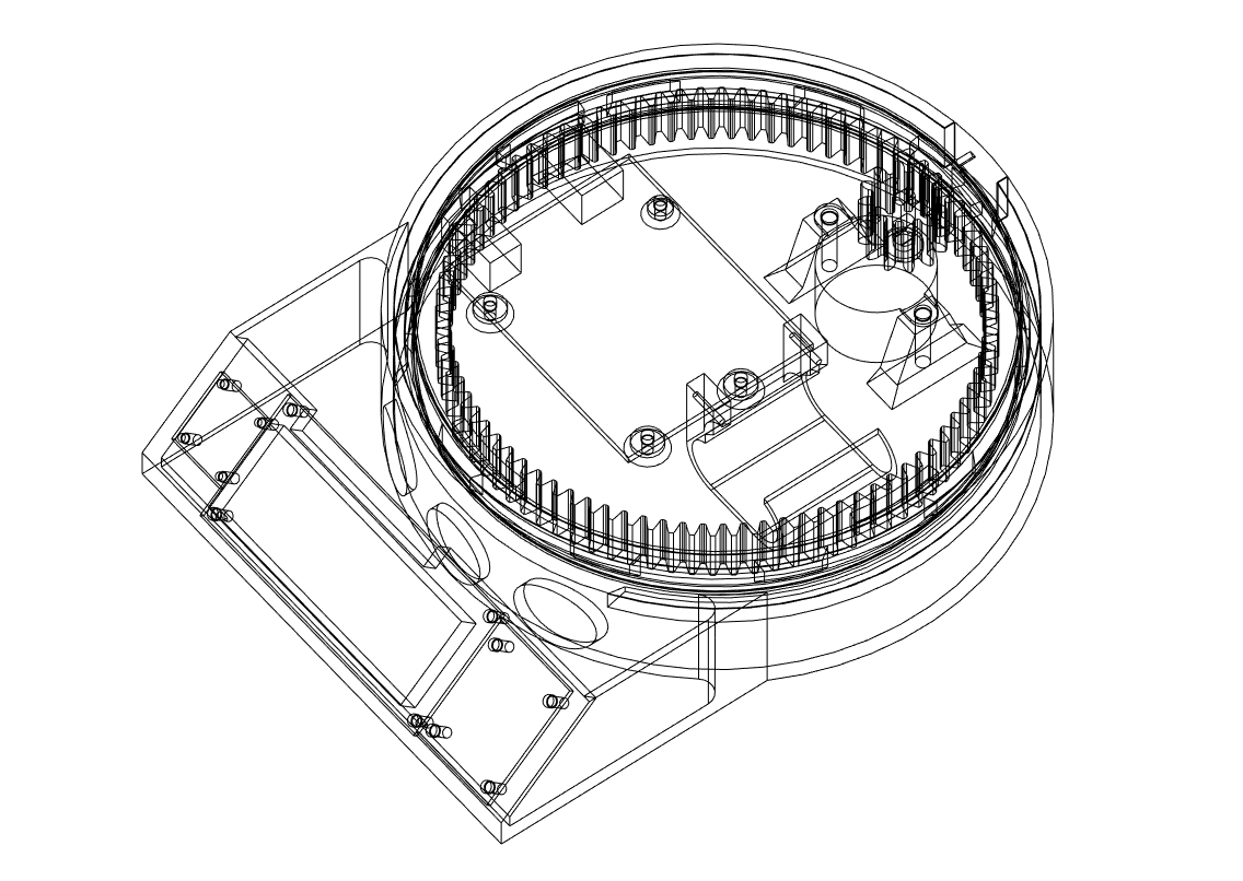
All the mechanical parts of this turntable are completely 3D-printed. The bearing for example is a print-in-place one which works great for this application. The print in place of moving objects adds to the simplicity of the build.

The reason I didn't connect the servo and stepper motor to the onboard 5V regulator and used an extra buck converter is because the stepper motor and servo draw to much current. Everytime the stepper motor rotated or stopped, the backlight in the LCD got brighter and dimmer due to the fluctuation in voltage. Using an extra buck converter takes the load from the 5 volt onboard regulator.

STL and Fusion 360 source files can be found here: https://bbprojects.technology/collections/stl-fusion-360-source-files/products/arduino-controlled-photogrammetry-3d-scanner-files

Video can be found here:

Camera_Turntable_Arduino_expansion_Final_version_1.ino

The original Arduino program for the turntable. It works but keep in mind there is room for improvement.

ino - 12.15 kB - 11/05/2019 at 21:02

Download

Code_contribution_from_Ryan_Hashiro.ino

The original code for the turntable but modified by Ryan Hashiro: 1. Added library calls and setups for an LCD with I2C backpack. 2. Added fast value change routines for the number of photogrammetry pics, motor speed, and cinematic turns. Holding joystick deflection for > 1 sec enters fast change mode. Change rate is proportional to amount of deflection. For the motor speed change is fixed at the slow speed since there's only 17 values to go through. 3. Added cancel routines for the photogrammetry and cinematic modes. Holding the joystick button down for > 2 sec kicks you out of the operation modes.

ino - 22.90 kB - 08/25/2020 at 21:02

Download

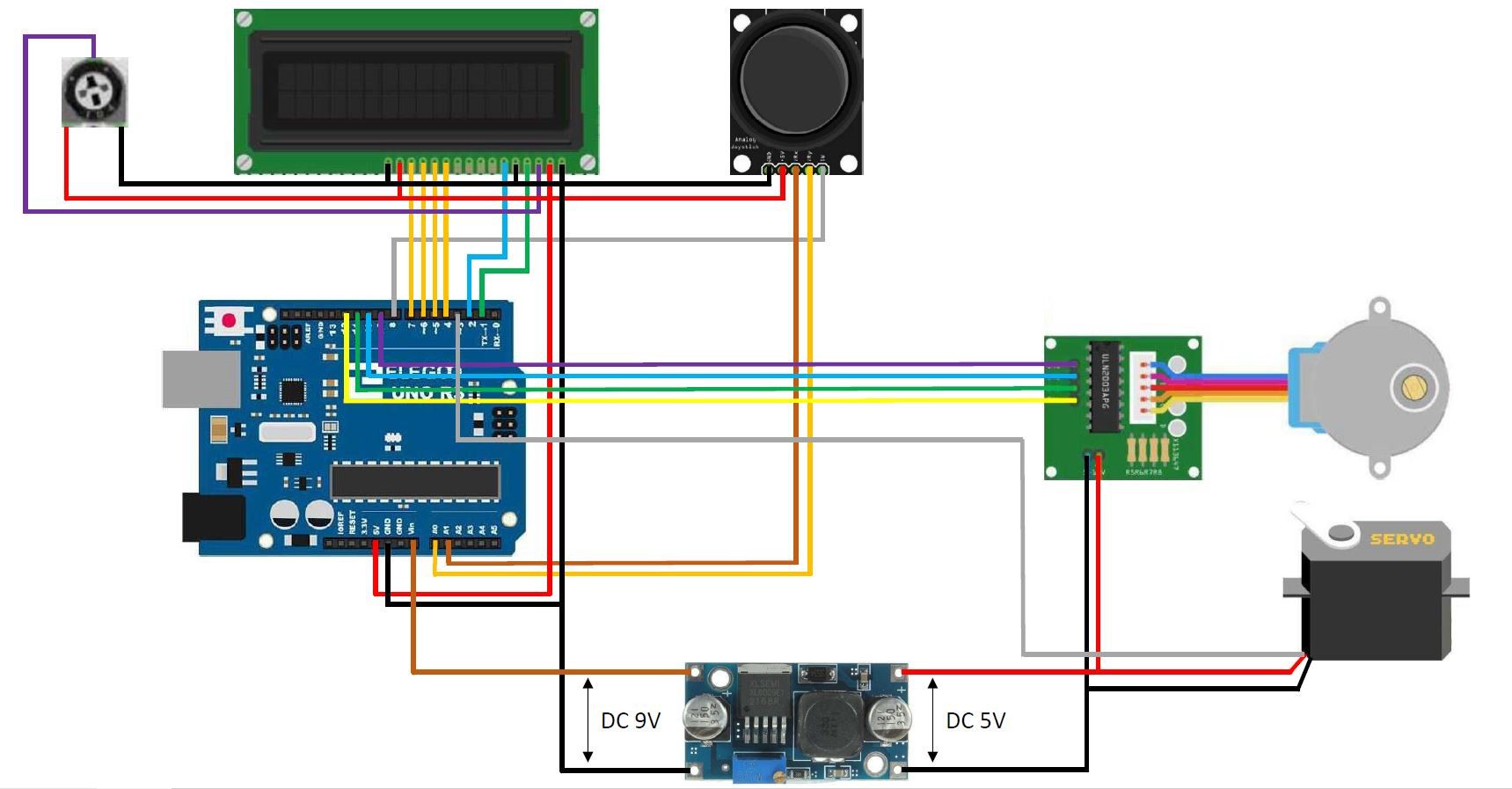
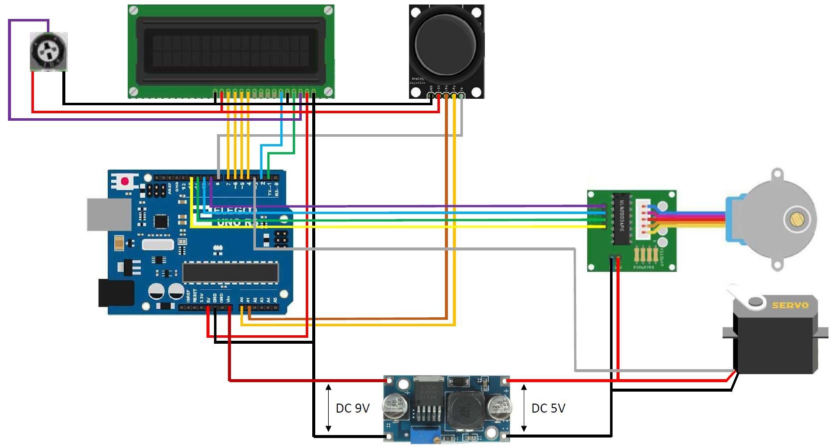
wiring diagram arduino controlled turntable V2.1.jpg

Wiring diagram for the turntable

JPEG Image - 175.86 kB - 11/24/2019 at 20:18

Preview

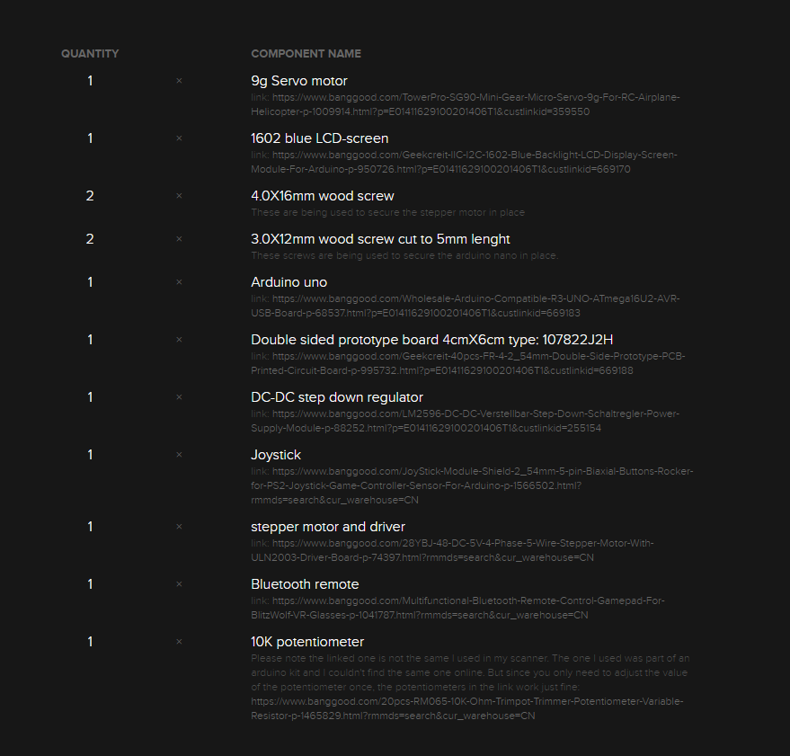
View all 11 components

  • Posted the stl-files also on Thingiverse

    Brian Brocken10/04/2020 at 22:42 0 comments
  • Posted the STL-files on MyMiniFactory

    Brian Brocken10/04/2020 at 22:40 0 comments
  • Parts list is now complete

    Brian Brocken10/04/2020 at 22:34 0 comments

    The links in the parts list have been updated and the list is now complete.

  • Posted the Fusion 360 source files on CGtrader

    Brian Brocken09/20/2020 at 19:41 0 comments

    I posted the original Fusion 360 source files on CGtrader for the people who want to tweek the design a bit.

    link: https://www.cgtrader.com/3d-print-models/hobby-diy/electronics/arduino-controlled-photogrammetry-3d-scanner

  • Added a code contribution from Ryan Hashiro to the files section

    Brian Brocken09/20/2020 at 19:37 0 comments

    Added a code contribution from Ryan Hashiro to the files section on this page.

    Code:

    /*
    
      Original code By Brian Brocken
      Contribution By Ryan Hashiro: 
      1. Added library calls and setups for an LCD with I2C backpack.
      2. Added fast value change routines for the number of photogrammetry pics, motor speed, and cinematic turns.  Holding joystick deflection for > 1 sec enters fast change mode.  Change rate is proportional to amount of deflection.  For the motor speed change is fixed at the slow speed since there's only 17 values to go through.
      3. Added cancel routines for the photogrammetry and cinematic modes.  Holding the joystick button down for > 2 sec kicks you out of the operation modes.
    
    */
    
    // #include <LiquidCrystal.h>  // use this library for the standard (non I2C) LCD
    #include <LiquidCrystal_I2C.h>  // RH - use this library for LCD displays with I2C backpack
    #include <Wire.h>  // RH - needed for the LCD I2C library.  SCL connects to pin A5.  SDA connects to pin A4.  Jumper the LED backlight pin on the I2C board
    #include <Stepper.h>
    #include <Servo.h>
    
    // LiquidCrystal lcd(1, 2, 4, 5, 6, 7);  // Use these pins for the 1602 lcd
    LiquidCrystal_I2C lcd(0x27, 16, 2);  // RH - use this for I2C LCD.  Assumes default address of 0x27
    
    const int SW_pin = 8; // digital pin connected to switch output
    const int X_pin = A0; // analog pin connected to X output
    const int Y_pin = A1; // analog pin connected to Y output
    
    int MenuNr = 0;   // Menu number
    int PhotoNr = 2;  // The amount of photos that have to be taken
    bool Flag1 = 0;   // This flag is only active during 1 program cycle (prevents constantly adding/subtracting 1 to the menu number when the joystick is pushed to the side) 
    bool Flag2 = 0;   // This flag is only active during 1 program cycle (prevents constantly adding/subtracting 2 to the photo number when the joystick is pushed up or down)
    bool Flag3 = 0;   // This flag is only active during 1 program cycle (prevents constantly adding/subtracting 1 to the RPM when the joystick is pushed up or down)
    bool Flag4 = 0;   // This flag is only active during 1 program cycle (prevents constantly adding/subtracting 1 to the turn number when the joystick is pushed to the side)
    bool Flag5 = 0;   // This flag is only active during 1 program cycle (prevents constantly adding/subtracting 1 to the RPM when the joystick is pushed up or down)
    bool Flag6 = 0;   // This flag is only active during 1 program cycle to clear the lcd
    int SwMenu = 0;   // Switch menu (Sub menu's in the main menu's)
    bool BtnFlag = 0; // This flag is only active during 1 program cycle (prevents constantly adding of 1 to SwMenu when button is pressed)
    
    // RH - added variables for fast change & cancel modes
    int FastChng = 0;  // indicates fast change value mode.  0 = off, 1 = delay mode, 2 = fast changing mode
    const unsigned long FastDelay = 1000;  // delay mode time (before values change fast)
    const unsigned long ShortInt = 100;  // short fast change interval
    const unsigned long LongInt = 300;  // long fast change interval
    const unsigned long BtnDelay = 2000;  // delay for button press to cancel operations.  Note this is an approximate delay, since stepper motor
                                         // suspends all program execution until motor finishes its move
    unsigned long SetTime = 0; // time value for fast change & button cancel modes.  Used to calculate time intervals
    bool BtnCancelFlag = 0; // This flag is used to detect when button is pressed for canceling operations
    bool MaxSwMenu = 0;  // This flag is used for detecting when the maximum SwMenu is reached
    bool CinCancelFlag = 0;  // This flag is used to trigger cinematic cancel.  1 = cancel cinematic operation
    int StepPoll = 480;  // number of motor steps to poll for cinematic cancel (at 15 rpm)
    int Cntr = 0;  // step counter for cinematic motor cancel
    // RH - end of added variables
    
    const int stepsPerRevolution = 2048;  // change this to fit the number of steps per revolution
    int FullRev = 14336;                  // 1 full revolution of the big gear -> Small-Big gear ratio is 7:1
    int rolePerMinute = 15;...
    Read more »

  • Added a youtube video to the details section of this page

    Brian Brocken09/20/2020 at 19:34 0 comments

  • Voltage Distributor

    Brian Brocken04/23/2020 at 09:44 0 comments

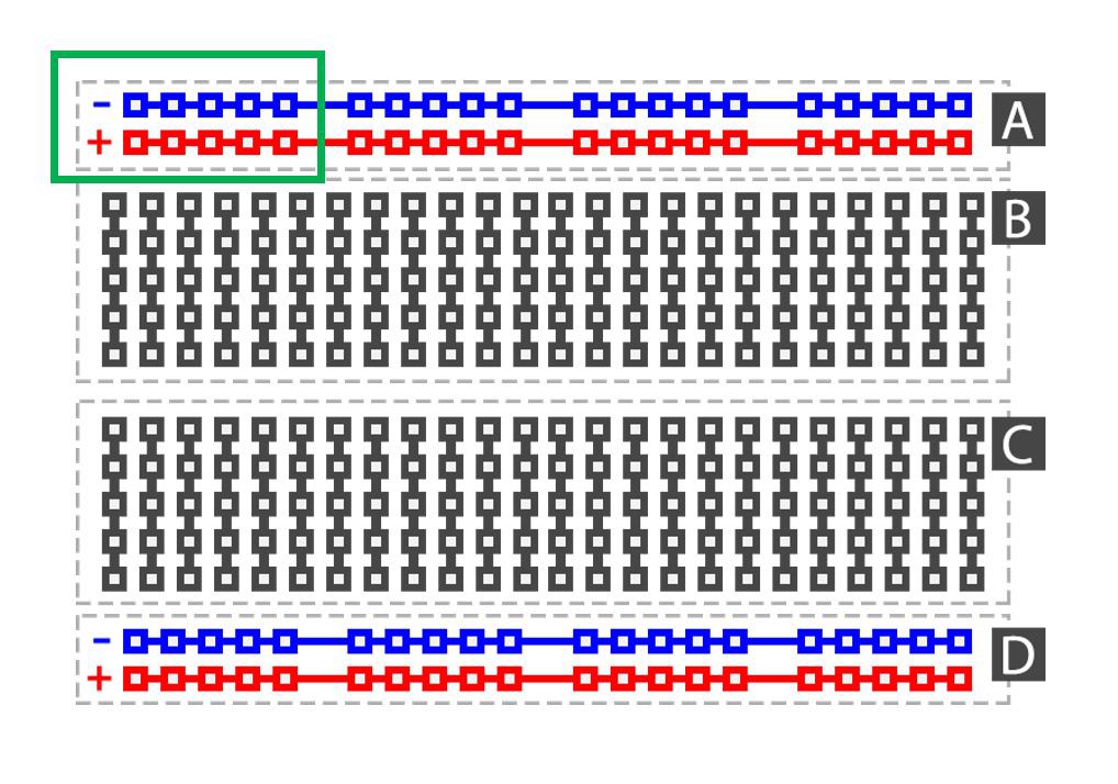
    At around 3:15 in the video () you can see I'm installing a little part next to the Arduino Uno. This is a homemade voltage distributor. It's sole purpose is to distribute 5V and 0V to other components. I made it using some double sided prototype board and soldering some 2.54mm female header pins on it. All the 5V pins are soldered together and all the 0V pins are soldered together, just like the + and - strips on a breadbord (see green box on picture below). Hope this cleared it out for some people.

    Double sided prototype boards: https://www.banggood.com/Geekcreit-40pcs-FR-4-2_54mm-Double-Side-Prototype-PCB-Printed-Circuit-Board-p-995732.html?p=E01411629100201406T1&custlinkid=669188
    2.54mm female header pins: https://www.banggood.com/10pcs-40Pin-2_54mm-Female-Header-Connector-Socket-For-DIY-Arduino-p-945516.html?rmmds=search&cur_warehouse=CN

  • Updated wiring diagram

    Brian Brocken11/24/2019 at 20:17 0 comments

    Made a very small adjustment in the wiring diagram to avoid possible confusion with the 5V and Vin pin. I changed the color of the Vin wire to orange, the 5V and Vin wire should not be connected together. The 5V wire goes up to the LCD,  joystick and potentiometer. The Vin wire goes to the DC-DC step down voltage regulator.

  • Arduino code added to the files section

    Brian Brocken11/06/2019 at 11:54 0 comments

  • Added a wiring diagram to the files section

    Brian Brocken11/05/2019 at 21:05 0 comments

View all 10 project logs

  • 1
    Step 1

View all instructions

Enjoy this project?

Share

Discussions

jarininger91 wrote 04/04/2024 at 17:03 point

The link to the bluetooth remote is no longer available. I've located the same device on Amazon (not an affiliate link): https://www.amazon.com/gp/product/B07FNQ3SDN

Thanks for a great build!

  Are you sure? yes | no

Arturbasmer wrote 09/04/2023 at 10:26 point

Hello Ryan!

Trying to compile the sketch in arduino ide, I get the following error:

'A1' was not declared in this scope; did you mean 'A0'?
   23 | const int Y_pin = A1; // analog pin connected to Y output
      |                   ^~
      |                   A0


I use UNO R3 MEGA328P and choose Generic ESP8266 module at list of boards... When i tried to choose Arduino UNO i got the error:

redefinition of 'void setup()

I'm new and have no experience with programming.

Pls, help me...

  Are you sure? yes | no

koerrie wrote 10/19/2022 at 22:30 point

Hi there, I've printed all the parts, connected all the hardware, but the Ryan Hashiro Code won't compile. Tried to solve several issues by following the error messages, but now I'm stuck and quite p**ed. It ends up with a Stray 342 error message in line 598 or so in the code. What to do?

  Are you sure? yes | no

yannvautrin wrote 09/15/2022 at 13:22 point

Hi All, just finished my build, uploaded the code, all I get is random characters on the display... can't read anything as it looks chinese to me...
Any idea?

  Are you sure? yes | no

julianstriba wrote 06/21/2021 at 19:30 point

Cordial Saludo.

Realice el proyecto, e investigando encontré esta pagina (https://www.instructables.com/Control-Phone-Camera-Wirelessly-Using-ARDUINO/) donde que me pareció interesante simplificar el hardware suprimiendo el servomotor por un transistor npn que en mi caso utilice un 2N 3904 y parte del código de esta pagina fue anexado al código de ustedes teniendo las dos posibilidades de usar el servo tocando el pulsador o el transistor cerrando el circuito y que no haya un desgaste o falla mecánica.

  Are you sure? yes | no

mark roberts wrote 05/22/2021 at 21:26 point

what are you using for a power source?  that's the only part you don't have listed

  Are you sure? yes | no

wisdomofdragon wrote 04/10/2021 at 23:41 point

Has anyone wired in a TRRS plug instead of using bluetooth?

  Are you sure? yes | no

AgentPothead wrote 03/16/2021 at 09:21 point

Has anybody tried this with an I2C oled display instead of the 1602? I have a few 128x32 and 128x64 sitting around I'm not using I'd prefer to use those if possible, but I'm not sure they will work. I suppose I can fire up the code and give it a shot :)

  Are you sure? yes | no

wisdomofdragon wrote 04/10/2021 at 23:37 point

Scroll through the comments. Ryan Hashiro provided code and describes wiring 

  Are you sure? yes | no

AgentPothead wrote 04/11/2021 at 03:00 point

That's using I2C 1602 which is what I ended up using. an Oled screen is one of these https://cdn-shop.adafruit.com/1200x900/931-10.jpg

  Are you sure? yes | no

Don Wright wrote 02/11/2021 at 03:38 point

If anyone is interested, I made some modifications to the code to support bluetooth and this camera app on a droid.  I can contribute the code.

The app is old, but it works. They have an app for the iPhone too.

They have sample code on the site.

https://www.tequnique.com/camerapro.php

  Are you sure? yes | no

bruno.ecard wrote 04/15/2024 at 14:17 point

hey, i'm interested by the bluetooth iteration you've made do you mind sharing it?

  Are you sure? yes | no

Modderman wrote 02/10/2021 at 19:14 point

I've read some people experience the bearing getting stuck when loading  the turntable with even the lightest of objects. And so did I.

I've added some support bearings under the inner geared ring. Basically the geared ring now runs on three bearings. The bearings are screwed to i little pillar that can be glued under the inner ring in de main body. Now the turntable can turn MUCH heavier objects.

  Are you sure? yes | no

Stella Gracia wrote 01/11/2021 at 16:08 point

Hi everyone! This is a cool project. I am using Meshroom to do my photogrammetry, however, somehow the camera positions seem to be covering only half circle even when the turntable is turning full circle. Does anyone have any tips for this?

  Are you sure? yes | no

leslie.adams wrote 01/05/2021 at 12:58 point

Hi, you mentioned a bluetooth interface with the phone/camera using a HC05/HC06. I know about the problems interfacing with IPhones etc. Just wondered how far you progressed with this interface as I would like to use BT rather than a mechanical switch/servo version. Many thanks for all you work. Les ...

  Are you sure? yes | no

AgentPothead wrote 03/16/2021 at 09:22 point

If you are still looking for HC05 version, I would look into this make he has code posted in the comments. https://www.thingiverse.com/make:808092

  Are you sure? yes | no

Coco Kopp wrote 12/22/2020 at 11:13 point

I'am very much a beginner, so it's quite possible I've missed something. But I build the project and to my great satisfaction it went very well thks to the great instructions... 

I have one problem left. my Stepper sometimes fail to keep the 3Dprinted bearing turning (with nothing on top it). 

This seems to come mostly from a voltage problem. I first couldn't get more then 4.5v out of my buck converter so I "tracked" the problem up to the "Vin" port of my Geekcreit Arduino uno that is actually also only giving me around 5v ... where my understanding is that it should give me the same voltage as the 9v battery plugged in the barrel connector. 

--> What am I missing? can the Vin output be changed to 9v somewhere? 

If I plug the 9V battery straight to the buck converter the problem is clearly reduced but it still sometimes struggle to push the printed bearings ... which leads me to the 2nd part of my (long) question.

I've printed the bearing version with the smallest tolerance and I had to massage it a bit before it started turning but now it is quite smooth. It doesn't need a lot of force to be turned be also definitely stop directly as soon there is nothing pushing it. 

--> should I expect a smoother behaviour from it, even tho it is plastic against plastic? 

--> can a dry Ptfe lubricant help reduce the friction ? 

--> should I just reprint it with bigger tolerances (I'm away from my printer for hollyday otherwise I would have tested that already)

Thanks for your futur answer and for the great project !!

Cheers

  Are you sure? yes | no

portals999 wrote 01/08/2021 at 15:28 point

Try using a wall wart 9V adaptor (not a battery), in the barrel power socket, you should see 9V on the Vin pin, this 9V goes in to buck converter and use the pot to control the Vout to be 5-6V and this goes to the stepper motor and servo.

Be careful if using 12V power with Geekcreit Arduino uno, mine was only rated for 9V input and I heated up and blew the voltage regulator chip (23p to fix), when using a 12V wall wart. My other Unos and Nanos are OK with 12V...

  Are you sure? yes | no

portals999 wrote 01/08/2021 at 15:29 point

I've had no issues with the gearing yet and haven't used any lubricants, sorting out the power might help, I'd do that first?

  Are you sure? yes | no

Coco Kopp wrote 01/21/2021 at 22:31 point

Thanks for your help :) ... Ended up doing a bit of everything at the same time... I'm now powering the buck converter directly with a 9V wall adapter which helped to reduce the problem (but not completely eliminating it) ... (any reason why this would be a worst idea then going through the Vpin ? )

I then used the WD40 dry PTFE spray to help with the friction on the bearings .... and reprinted the small gear in PCblend as I noticed some slight deformation on my previous PLA gear due to the heat from the stepper (also remodelled that gear so it sits tighter on the stepper - the tolerance were a tiny tiny bit loose  previously)

So far so good now. It behave flawlessly since theses change :) 

And I started to use it on upcoming photogrametry project... 

  Are you sure? yes | no

Ken Sikora wrote 12/15/2020 at 05:33 point

How is the front panel supposed to connect? It doesn't seem to snap in place, and there are no screw holes. It's just kind of lightly resting on top of the front section of this thing. Am I missing something?

  Are you sure? yes | no

Ryan Hashiro wrote 01/08/2021 at 09:03 point

Yes - the front panel just sits on the frame.  I hot-glued mine on.  I only used a couple of "dots" of hot glue - I wanted it to be easily removable in case I need to service the wires/connections in the future.

  Are you sure? yes | no

Steve Gadd wrote 12/10/2020 at 15:21 point

This turntable printout is pretty much bang on for size - http://ideate.xsead.cmu.edu/gallery/projects/digitool-photogrammetry-table-and-printed-rock

  Are you sure? yes | no

Ryan Hashiro wrote 12/08/2020 at 11:13 point

When using this for photogrammetry, one thing I have discovered that helps a lot is laying some sort of pattern on the turntable.  I printed out a random black-and-white pattern on a sheet of paper, cut it out to the size of the turntable and taped it on.  The photogrammetry software thus has additional points of reference for object rotation.  I think that without a pattern on the turntable, the software tends to have errors in detecting turntable rotation (since it is pretty much featureless), and thus throws the entire rendering off.  

  Are you sure? yes | no

Brian Brocken wrote 12/08/2020 at 14:49 point

That's a great tip Ryan! What photogrammetry software are you currently using?

  Are you sure? yes | no

Ryan Hashiro wrote 12/09/2020 at 11:35 point

For the 3D image construction I use either Meshroom or 3DF Zephyr (the free version).  You can only use 50 images max with the free version of Zephyr but I seem to get more consistent results with that.  I am not limited to number of images with Meshroom - you would think that more images = better quality, but for some reason the rendering doesn't come out as great.  There's a TON of settings you can tweak in Meshroom - I have a feeling that the rendering can be improved by adjusting the settings, but this is too overwhelming for me.

For mesh editing I use Autodesk Meshmixer (free version).  I mostly use this to slice out and delete the turntable pattern from the bottom of the model.

  Are you sure? yes | no

portals999 wrote 12/02/2020 at 14:10 point

I just built this, very nice project! Save yourself a lot of hassle though and get the 1602 LCD with the I2C module on the back, only 4 wires to connect from it's jumpers (VCC, GND,  SDA and SCL) and no need for the 10K pot as you can use screwdriver to adjust brightness on back of I2C board. This simplifies wiring considerably. The buck converter is important though, not enough power otherwise! I'm going to have a go at re-doing the front cover to remove the hole for the pot as it's no longer required. The holder print for the servo is a little flimsy but very impressed with the case and especially the gearing print (CR 6-SE)! Great job!

  Are you sure? yes | no

portals999 wrote 12/02/2020 at 14:13 point

Ryan Hashiro's updated sketch for I2C is great too!

  Are you sure? yes | no

gary_laevsky wrote 01/05/2021 at 20:07 point

Any chance you could post a wiring diagram using the I2C?  I'm a total newbie and would greatly appreciate it.

  Are you sure? yes | no

Ryan Hashiro wrote 01/08/2021 at 09:21 point

Hi gary_laevsky - I don't know how to post a wiring diagram here, so I'll try to explain it best I can.  Refer to the jpg wiring diagram on this project page.  The red & black lines on the far right of the LCD symbol is the power connection (5V and gnd) - those should be connected to the power terminals of your I2C LCD.  You don't need the other 10 wires shown to the left of the power wires.  Instead, connect the SDA terminal of the I2C to pin A4 of the arduino, and connect the SCL terminal to pin A5.  That's it - you are done with the LCD connection!

The I2C board often has a built-in potentiometer to control the contrast (at least mine did), so you don't really need to have an external pot to control the contrast (the symbol at the top left of the jpg diagram).  If yours doesn't have a built-in pot, then you can connect the external pot as shown in the diagram - just connect the 3 pot wires as shown (you will need to connect this to the "normal" LCD interface pins on the main board, not the I2C board.

Make sure you modify the arduino sketch/program to use the I2C (comment out the "regular" LCD sketch lines).  My sketch mod already has the regular LCD lines commented out with the double-slash symbols.

Hope this helps!

  Are you sure? yes | no

portals999 wrote 01/08/2021 at 15:34 point

If you're using a Nano then for the LCD display you need to user pin A4=SDA and pin A5=SCL as the sketch has wire.h sketch included in it.

If you're using an Uno you can just use the dedicated SDA and SCL pins (the 2 pins nearest the USB socket on the board).

  Are you sure? yes | no

YH wrote 11/08/2020 at 18:08 point

Does anyone have the code to use a bluetooth remote shutter? As an electrician, wiring is easy but coding is very new for me so, trying to figure it out. Any help is greatly appreciated!

  Are you sure? yes | no

AgentPothead wrote 03/16/2021 at 09:16 point

I think with this design the button is physically pushed by the servo, so it would just bethe code that activates pin 3.

  Are you sure? yes | no

John wrote 10/01/2020 at 00:50 point

Great project. Working my way through it slowly here as pieces arrive.

Just checking -- with the updated lcd module that has the i2c backpack I'm assuming there's no need for the potentiometer anymore unless I de-solder the i2c backpack and hook up the way it was originally?

It looks like the i2c library in Ryan's updated code only has the option of turning on the backlight or not. (see "lcd.backlight();" on line 66)

  Are you sure? yes | no

Ryan Hashiro wrote 12/08/2020 at 09:17 point

On my i2c backpack the board had a small pot on it to control the contrast, so I didn't really need a front panel pot.  Usually once I set the contrast to my liking I don't have to touch it anymore.  But I added one anyway (just because I could  :)

If you want to add an external pot, you can just hook it up the way it's shown in the original schematic - no need to desolder anything.  What will happen is that the i2c onboard pot and the external pot will be in parallel, so you will have to preset the i2c pot to allow a decent contrast range adjustment with the external pot.

  Are you sure? yes | no

gary_laevsky wrote 01/05/2021 at 20:07 point

Any chance you could post a wiring diagram using the I2C?  I'm a total newbie and would greatly appreciate it.  Found it!

  Are you sure? yes | no

Anonymouslemming wrote 09/25/2020 at 13:13 point

does anyone have any pointers on the pin connections for the screen? I can’t work out which end to start from in the layout drawing. I have VSS on pin 1 and K on pin 16. Full list (1-16) is vss vdd v0 rs rw e d0 d1 d2 d3 d4 d5 d6 d7 a k

Thanks!

  Are you sure? yes | no

Similar Projects

Does this project spark your interest?

Become a member to follow this project and never miss any updates