 Patchr
-
1Designing and Exporting
Check it out — all we need to do is log in to Patchr, select the “Explorer Uno” template next to the create new project button, annnnnnnnnd… Bada bing, bada boom! It’s ready to go. You can change the board footprint, add components, or just export as is.
We've included a BOM with the correct components linked below or you can use the component section above to buy items individually.
-
2Assembly!
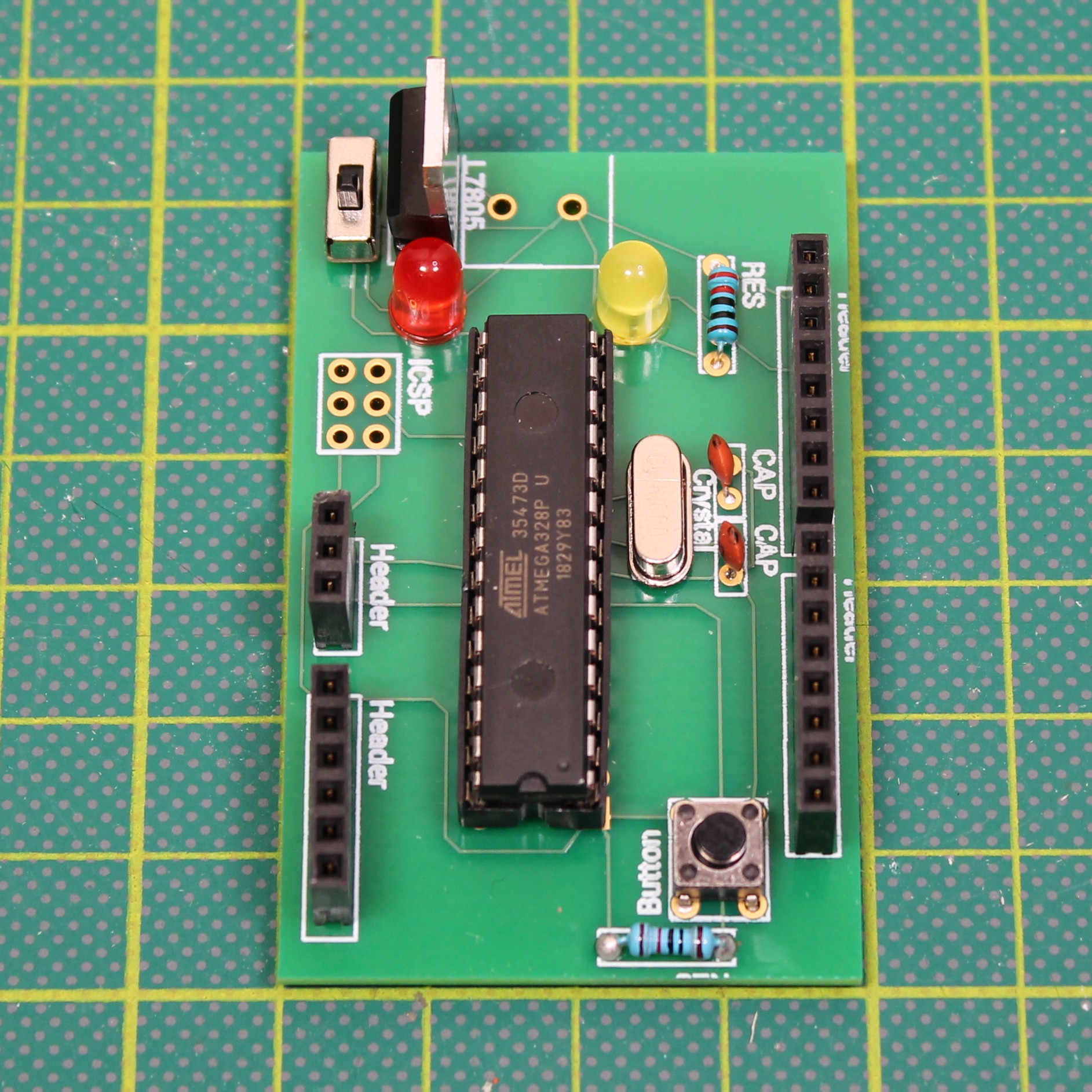
Once you've received your components and your PCB, you're ready to assemble them. There are a lot of configurations that can work, so keep in mind the final shape of your PCB is entirely up to you and the project you are building!
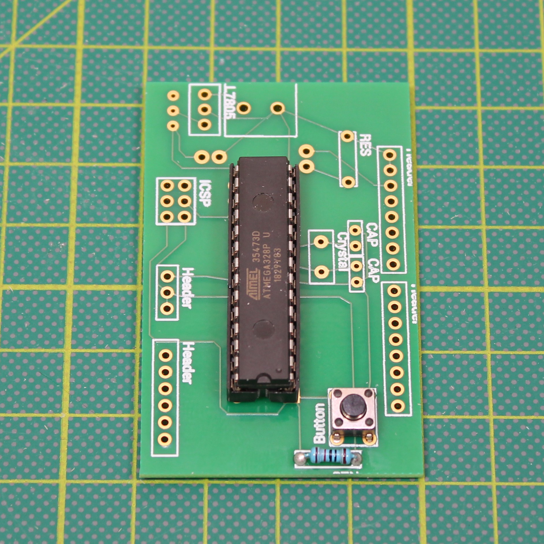
Let's start with the core of the Explorer Uno, the ATmega328, the brains. This is what tells your project what to do and when to do it.
![]()
Tip: Make sure that the indent on the top of this chip is facing down. You can also use a 28 pin IC socket to make it a bit easier to program and flip in case the ATmega328 is upside down.
![]()
Button & Resistor - This helps reset your project once the software has been uploaded into the ATmega328.
![]()
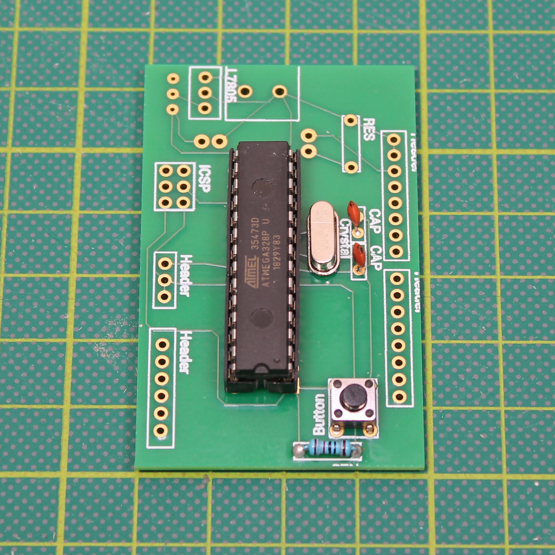
Clock & Capacitors - Time! This 16 MHz beauty counts the seconds so you don’t have to.
![]()
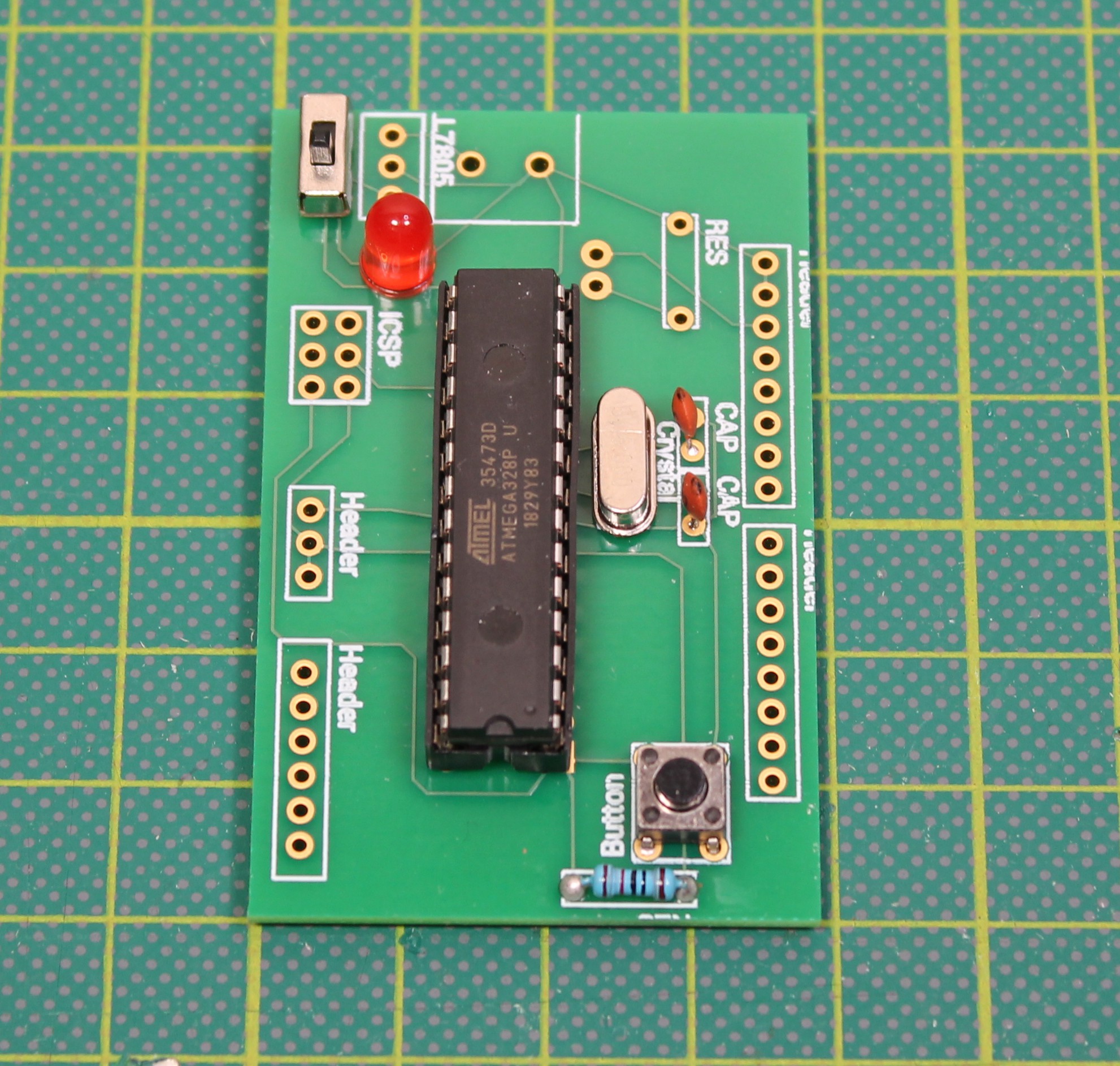
Switch - On and off, on and off, on and off. We added a red LED so you can tell when the Explorer is on.... or off.
![]()
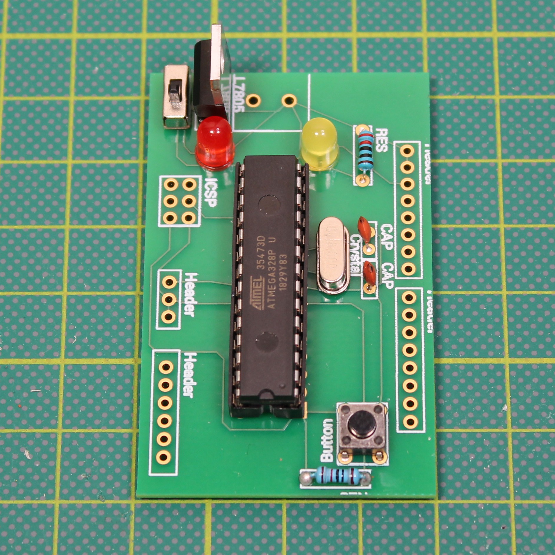
LED Pin 13 + Resistor - This is your proof of life light when uploading software or running simple sketches look at this light to be sure everything is running smoothly.
![]()
Voltage Regulator - This bad boy helps make sure the only thing you are blowing is people’s minds… and not the components on your PCB. We like to use a 9V battery to power our projects, and this will drop it down to 5V to keep everything running smooth.
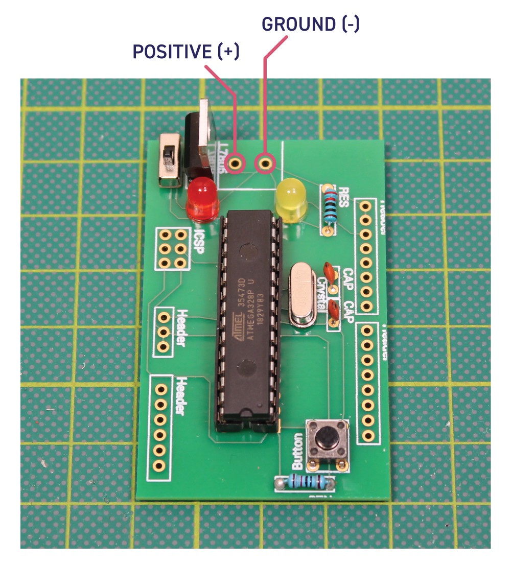
![]()
Power - There are so many options here. You can use anything that supplies 5V or more. Just connect the positive and negative leads to the through holes as shown in the diagram above.
![]()
Headers: These are totally optional — we like to keep them open to solder directly to or you can use jumper cables and female headers to prototype with.
-
3Programming Your Explorer Uno
So here’s the fun part. Let’s upload your sketch to the Explorer Uno. We suggest you do it in one of two ways. The first is to place your ATmega328 in an empty Arduino Uno and upload how you would normally upload to your Arduino.
The second is to use an empty Arduino Uno as a bridge to the Explorer Uno to program it. You will want to wire up the Arduino using this diagram:
![]()
-
4Party Time!
We hope this helps you create exactly what you’ve imagined! Please don’t hesitate to reach out with any questions! We are here to help.
Exporer Uno PCB Software Template
Go beyond the Arduino with this customizable Uno template. Take your prototypes to the next level!


Discussions
Become a Hackaday.io Member
Create an account to leave a comment. Already have an account? Log In.
Decoupling the Analog Voltage Supply
=================================
I have build an Arduino UNO on a breadboard before. When you look at the Vcc (using an oscilloscope) you will see that there is plenty of noise being generated by the chip. For this reason the the chip has a separate analog power supply (i.e. AVcc). If you check the datasheet for the ATmega328P you will see they recommend a 10uH inductor between Vcc and AVcc, and a 100nF capacitor between AVcc and ground, to decouple the analog circuitry from the digital circuitry. In my case I used a 10R resistor for the inductor and a 1uF (monolithic) capacitor, instead to decouple AVcc. In my case I connected Aref to AVcc as well.
As you probably know, you can also use a USB2TTL Serial adapter to both power and talk to the board as well.
Anyway, please take my comments in a positive way.
Regards AlanX
Are you sure? yes | no