Close
0%
0%

SPST Relay Logic

SPST relays are cheap and easy to make. But they're not as intuitive as SPDT/DPDT relays for logic purposes.

Similar projects worth following

There have been a number of digital logic projects that use relays.  Most relay logic I've seen relies heavily on double-throw (form C) relays.  I'm interested in circuits that use the simpler single-throw kind of relay.  

SPST relays (1 form A) have a number of advantages.  They're the simplest, cheapest, and generally the most reliable kind of relay.  Also, most reed relays are SPST-NO relays, and reed relays also have some advantages for logic.

So, what can be built with just SPST relays?
  • the road to functional completeness

    retrac11/13/2019 at 03:28 0 comments

    In the previous post, I looked at ways to implement AND, OR and buffers with relays.  But a full logic family requires the ability to invert a value.

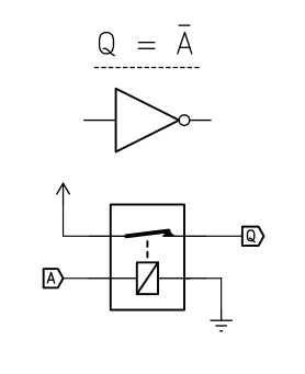
    With a NC relay this is trivial:


    When A is zero, Q is 1.  When current is applied to A, the relay opens and Q becomes logical 0.

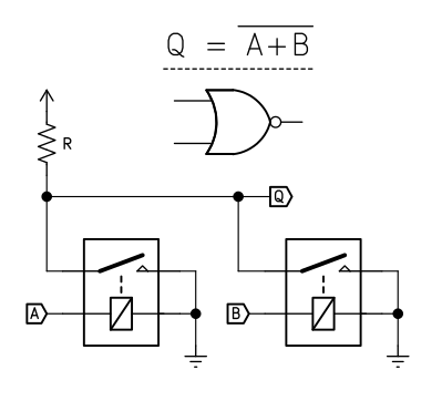
    This can be extended to produce a NOR gate:

    Q is 1 only when A and B are both 0.  

    Note how this circuit mirrors the AND gate.  Per DeMorgan's Law, AND is equivalent to NOR with both its inputs inverted.

    NAND can also be implemented by mirroring the previous OR gate using NC relays instead.

    Negation with Normally-Open Relays:


    With a little care, it is also possible to implement negation with a normally-open relay:

    When A is low, Q is pulled up to supply through R.  When A goes high, Q is shorted to ground and goes low.
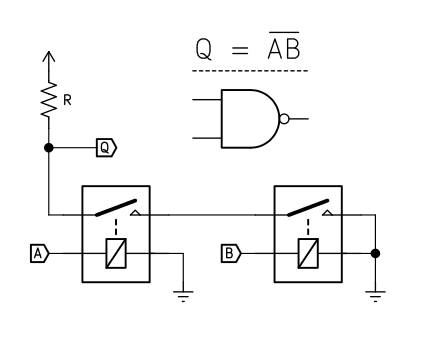
    Note that this gate has some properties different from the previous ones.  First, the output swings between supply and ground, not supply and not connected.  Second, the ability of this gate to drive further gates is limited by the value of R.  Finally, this gate will consume power, dictated by the value of R, every time the input is high, as power flows to ground through it. 

    R should be selected as a compromise between current use and ensuring that Q can drive inputs.  Too low a value of R and the gate will draw enormous power whenever the output is low.  Too high and it won't be able to drive any gates itself. 

    I suspect it will often be desirable to follow this gate with a regular buffer, to provide isolation, normal supply/NC levels, and higher fan-out.

    Despite these drawbacks, this gate does work and it proves that SPST-NO relays are capable of functional completeness.

    This can be extended to implement NAND:

    As well as NOR:

    At this point, we have functional completeness and combinatorial and sequential logic can be implemented with these gates.

    But that's far from the end of the story.  It's often possible to implement a function with far fewer relays than a naive Boolean equivalent might suggest.  A D-latch normally requires 4 NOR or NAND gates which would be 8 relays.  But I've got a circuit that can do it in just a few relays.  More on that later.

  • relays, logic levels, and basic gates

    retrac11/08/2019 at 02:43 0 comments

    Before I get into the circuits, I should talk about logic levels.  In most transistor-based logic circuits, Boolean 0 and 1 are conveyed with high and low voltage levels, such as nominal 0 V and +5 V in TTL. 

    This convention works fine with relays too.  However, leaving the coil not connected (NC, high impedance, high-Z) is logically the same as connecting both sides of the coil to ground.  This is sometimes called a floating zero. It turns out that implementing logic with NC and supply rather than ground and supply is a bit simpler, at least for SPST relays. 

    Mixing ground and supply as inputs to relay logic is also a great way to accidentally create a short-circuit.

    These facts encouraged me to take an approach where logic outputs are either NC or connected to a source.   Inputs are usually a single coil and are sinks.  This isn't the only approach, and circuits can be simplified by violating this rule of thumb.  It still seems a good idea to adopt a floating zero.

    So, let's begin. 

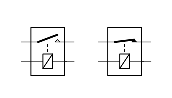
    The relay: 

    On the left we have symbols for a normally-open (NO) relay and on the right a normally-closed (NC) relay. 

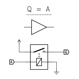
    The non-inverting buffer:

    The coil is connected to ground and input A.  The switch is connected to supply and output Q.  When the coil is energized by current from A flowing to ground, the coil energizes and closes the switch.  Supply voltage is then available at Q.  Summarized, when A is NC or ground, Q is ground.  When A is source that can drive a coil, Q is that source.

    This buffer has two useful properties.  First, the circuit's input and output are always electrically isolated, preventing a supply connected to Q further down the circuit from flowing back into input A.  It is also an effective "amplifier".  When connected directly to supply voltage, this circuit can drive any number of relay coils in parallel, up to the amp rating on the relay's switch.  This is necessary for some circuits which can only source a limited amount of current.

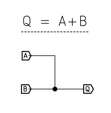
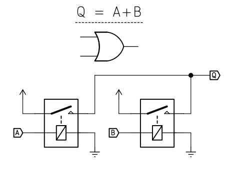
    Logical OR:

    In many cases, a simple wired OR suffices.  If all the inputs are not connected, the logic level is 0.  If any are connected to +V then it is logic 1:

    Sometimes it is necessary to isolate the prior stages.  The above buffer can easily be chained to provide an OR gate:

    An arbitrary number of inputs is possible here.

    Logical AND:

    With this circuit, if Q is only true when B and C are both true as well. This circuit can also be chained for an arbitrary number of inputs.  Note that A is simply switched through, which is a potential hazard.

    In the next post, I'll look at inverters.

View all 2 project logs

Enjoy this project?

Share

Discussions

Ken KD5ZXG wrote 11/19/2020 at 03:09 point

Mechanical is fun, but transmissions gates are worth at least being aware of.

Dual SPST, 3 Ohms when closed, 4.5nS to switch, 250pS to propagate.

ti.com/lit/ds/symlink/sn74cbt3306c.pdf

Provides no easy way to fake a diode bridge XOR across the coil though.

DPQT like 74CBT3253 provide a straighforward way to fake that bridge.

More throws than you were after, but no obligation to connect all of them.

  Are you sure? yes | no

Dr. Cockroach wrote 09/07/2020 at 10:37 point

You have had this project up for 10 months and I just now have seen it. Same thinking as with my Light Logic :-)

  Are you sure? yes | no

retrac wrote 11/17/2020 at 01:05 point

Yes, your Light Logic is definitely one of the inspirations.  I have neglected it for a while, but I've got some notes.  I should type them up.

  Are you sure? yes | no

Dr. Cockroach wrote 11/17/2020 at 10:35 point

I really would like to see what you continue to do with it. My LL processor is on a short hold and currently working on a LL sound synth idea.

  Are you sure? yes | no

Similar Projects

Does this project spark your interest?

Become a member to follow this project and never miss any updates