Close
0%
0%

HiCuDriver

convert a BLDC driver in High Current Driver. Provides a Step/Dir interface like DRV8825 A4988 and converts 12@1A in coil current up to 70A

Public Chat
Similar projects worth following
The aim is it to convert a BLDC driver which is compatible with BLheli_32 software in a High Current Driver. Only some capacitors, a coil and a software update should be enough. The project will consist of three steps

1. figure out controller pinning of a cheap 35A BLheli_32 ESC
2. build a buffer circuit to supply the current peaks
3. build a firmware for the controler

First Step
figure out the schematic for a PCB compatible to BLHeli32 firmware
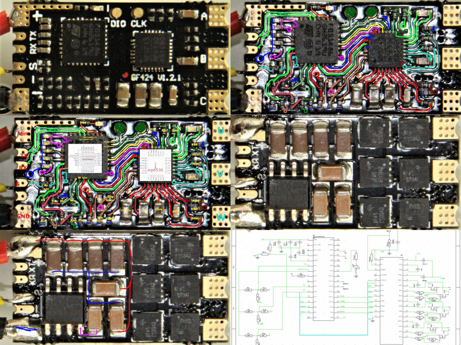
The image above shows the pictures used to figure out the pinning

  • Top side to see the components
  • Top side with bight flash to see the traces
  • Top side with  hand colored traces
  • Top side with some notes from datasheets
  • Bottom side to see the components
  • Mirror bottom with bight flash to see the trace
  • Bottom side with hand colored traces
  • Bottom side with some notes from datasheets
  • The finish schematic


Second Step

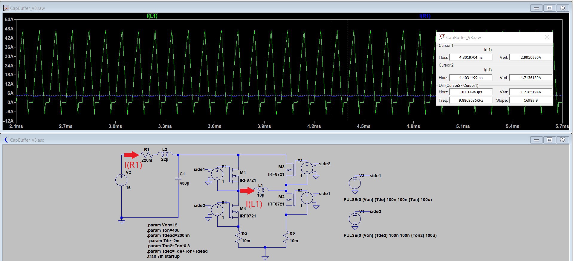
The image above shows the a H-Bridge simulation with a single motor winding and the buffer circuit. The current in to the buffer circuit is shown in blue  I(R1) and about 4.7A. At the same time the green current I(L1) in the motor winding is up to 45A. The inductance L2 (22µH) and the capacitor C1 430µF is needed to reduce the ripple current I(R1) to about 1.7A. The resistor R1 limits the current at startup when the capacitor is empty. 
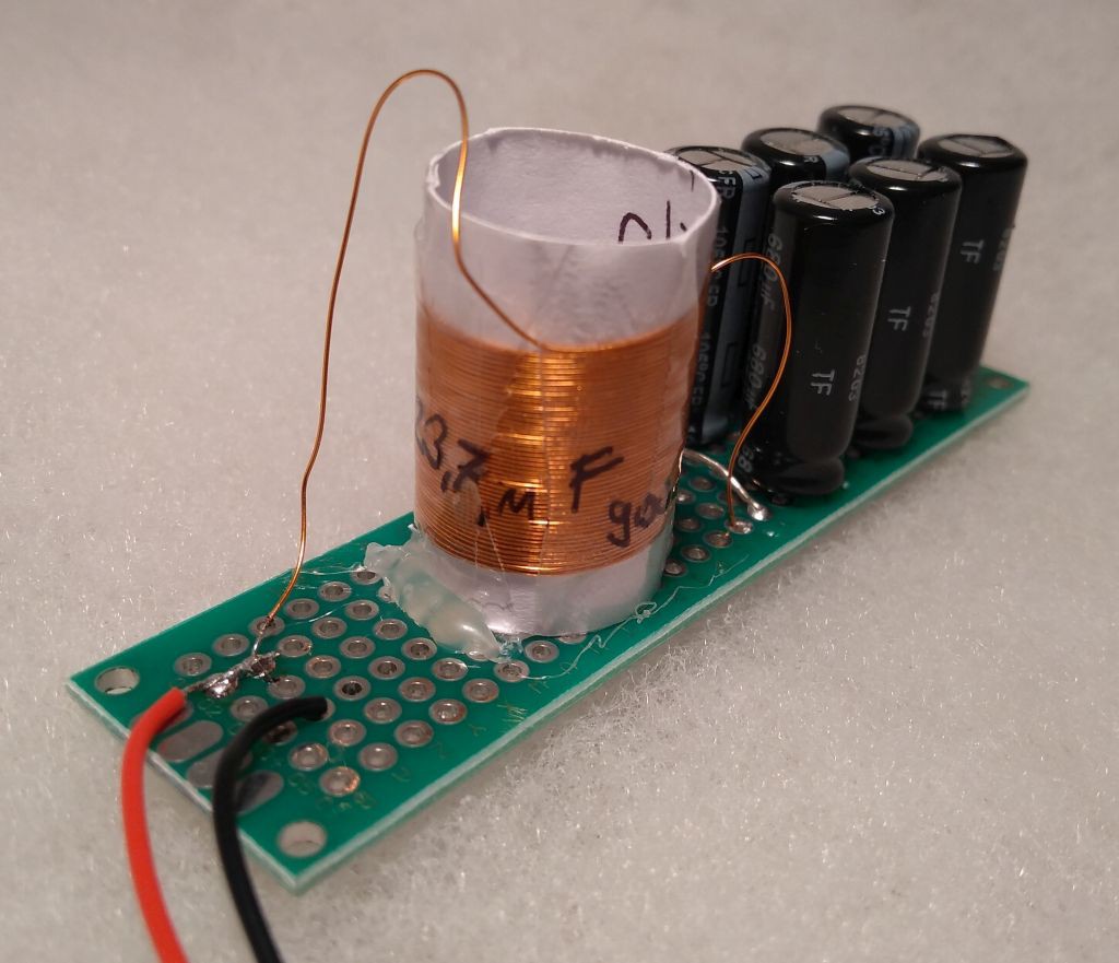
On the image above is the prototype of the buffer circuit shown. The coil has 23µH and consist of 45 winding of 0.3mm wire with a coil diameter of 15mm. I used 6 x 680µF / 25V low ESR electrolytic capacitor in parallel. I used these big capacitor because the electrolytic capacitors have to provide the ripple current of the motor winding with about 45A. The current rating of on capacitor is 1.7A therefore all 6 in parallel can sustain 10.2A. I hope that with 4 time overload the capacitors will not be too hot.

Third Step
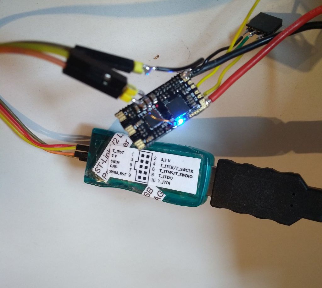
"Hello World" the LED works. For further detail see the log

BufferCircuit.asc

LTSpice simulation of a H-Bridge with a single motor winding and a buffer circuit

asc - 2.96 kB - 11/27/2019 at 21:39

Download

HiCuDrive_Schematic.pdf

Schematic of a BLHeli 32 ECS

Adobe Portable Document Format - 81.82 kB - 11/17/2019 at 12:25

Preview

l78l.pdf

Datasheet to the linear regulator

Adobe Portable Document Format - 1.56 MB - 11/08/2019 at 16:52

Preview

stm32f051k8.pdf

Datasheet to the micro controller

Adobe Portable Document Format - 1.95 MB - 11/08/2019 at 16:52

Preview

mp6530.pdf

Datasheet to the 3 phase full bridge mosfet driver

Adobe Portable Document Format - 1.23 MB - 11/08/2019 at 16:52

Preview

View all 6 files

  • "Hello World"

    Chris.deerleg12/07/2019 at 11:37 0 comments

    For establishing a connection to the PCB are following steps required:

    • Connect ST-Link to PCB
    • Remove the write protection (not sure if required)
    • modify Arduino IDE
      • reduce flash speed
      • create a board variant
      • add a board in Arduino IDE

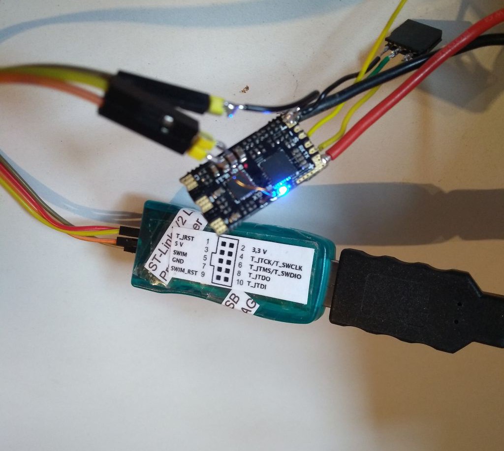
    On the image above is a picture of the ST-Link programmer connected to the PCB. The ST Link programmer pin "T_SWSCLK" is connected to testpoint which is marked as "DIO"  and "T_SWDIO" is connected to testpoint which is marked as "CLK". If the pin are interchanged, it will not be possible to get a connection to the PCB.

    As Next remove the write protection.

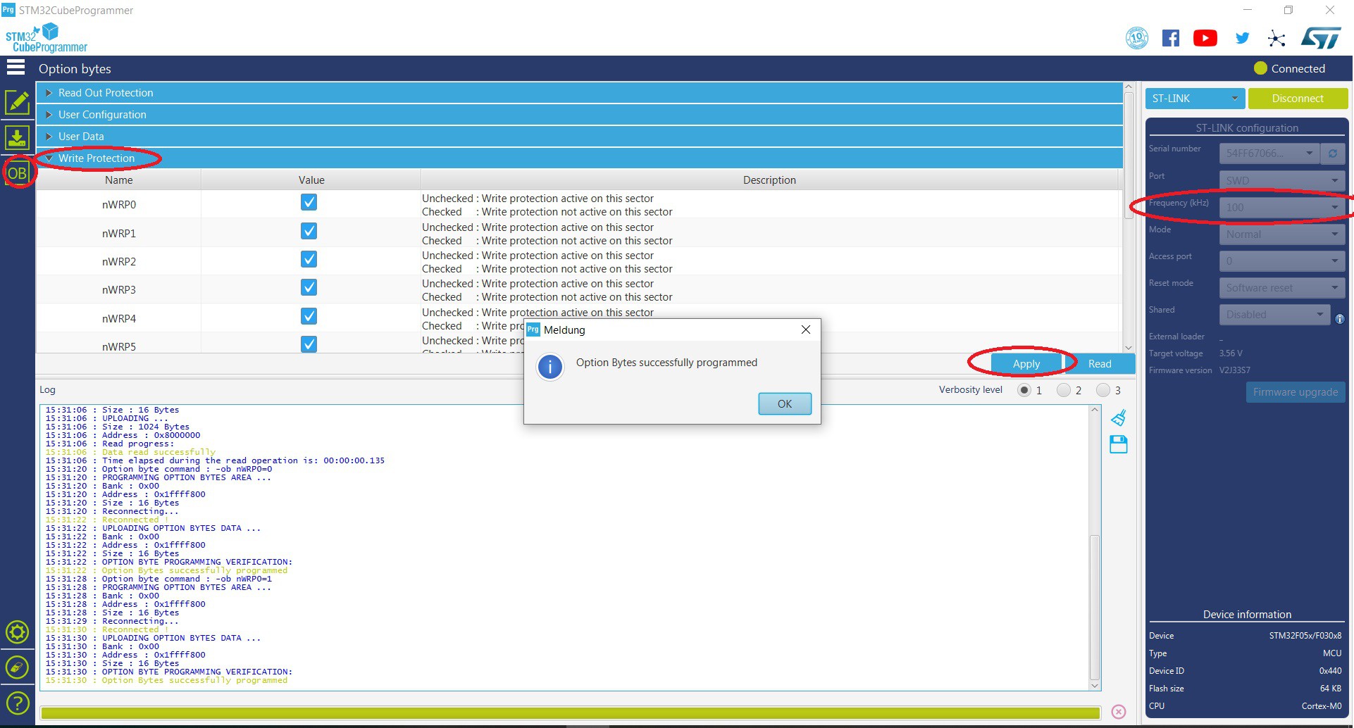
    Above is the STM32 cube programmer shown. The tool is available on the STMicroelectronics home page. After the successful installation it should be possible to establish and connection to the PCB. The default communication frequency of  4000 kHz  don't work for me. I used 100 kHz as frequency to get a stable connection. In the OB menu under sub-menu "Write Protection" tick all boxes and apply.  Once done the write protection is successfully removed. 

    To run a blink sketch the following is to do.
    • reduce the flash frequency
    • create a board variant
    • add a board in Arduino IDE

    Reduce the flash frequency

    the following show how to change the programmer frequency in a Arduino IDE with a STM32F.

    ..\ArduinoData\packages\STM32\tools\STM32Tools\1.3.1\tools\win

    in the Arduino path shown above is the stm32CubeProg.bat to modify.

    :prog
    %STM32CP_CLI% -c port=%PORT% %MODE% %ERASE% -q -d %FILEPATH% %ADDRESS% %OPTS%
    exit 0
    
    :prog
    %STM32CP_CLI% -c port=%PORT% freq=480 reset=SWrst %MODE% %ERASE% -q -d %FILEPATH% %ADDRESS% -v %OPTS% 
    exit 0

    at the end of the stm32CubeProg.bat add "freq=480 reset=SWrst" to reduce the frequency and change to software reset. Further add "-v" to verify the code after flashing.

    Create a board variant
    The following shows how to create a own board variant for the Arduino IDE.

    ..ArduinoData\packages\STM32\hardware\stm32\1.7.0\variants

     in the folder variants (path above) are all board listed which are usable in the Arduino IDE .

    to create a new board variant for the HiCuDriver copy the DISCO_F030R8 folder and renamed it to HiCuDriver_Dshot.

    Add a board in Arduino IDE menu

    the following shows how to add the own board variant to the tool menu in the Arduino IDE.

    ...ArduinoData\packages\STM32\hardware\stm32\1.7.0

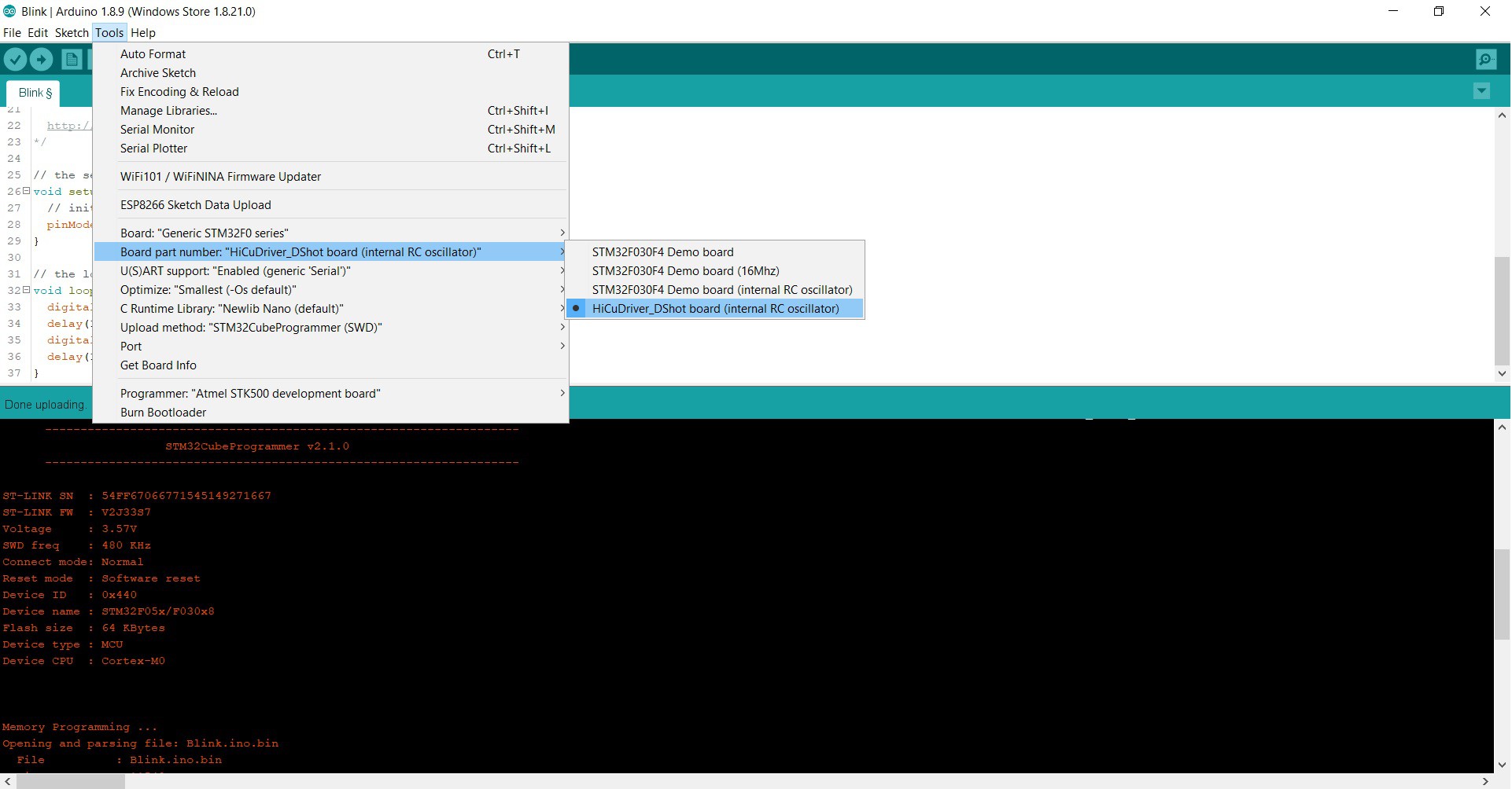
    it is necessary to change the "boards.txt" which is to find in the path shown above. add the lines of "# HiCuDriver_DShot" in the section "# Generic F0".  Further details see below.

    ###############################
    # Generic F0
    GenF0.name=Generic STM32F0 series
    
    GenF0.build.core=arduino
    GenF0.build.board=GenF0
    GenF0.build.mcu=cortex-m0
    GenF0.build.series=STM32F0xx
    GenF0.build.cmsis_lib_gcc=arm_cortexM0l_math
    GenF0.build.extra_flags=-D{build.product_line} {build.xSerial}
    
    ....
    
    # DEMO_F030F4_HSI board
    GenF0.menu.pnum.DEMO_F030F4_HSI=STM32F030F4 Demo board (internal RC oscillator)
    ....
    
    # HiCuDriver_DShot
    GenF0.menu.pnum.HiCuDriver_DShot_HSI=HiCuDriver_DShot board (internal RC oscillator)
    Disco.menu.pnum.HiCuDriver_DShot.node="No_mass_storage_for_this_board_Use_STLink_upload_method"
    GenF0.menu.pnum.HiCuDriver_DShot_HSI.upload.maximum_data_size=4096
    GenF0.menu.pnum.HiCuDriver_DShot_HSI.upload.maximum_size=65536
    GenF0.menu.pnum.HiCuDriver_DShot.build.mcu=cortex-m0
    GenF0.menu.pnum.HiCuDriver_DShot_HSI.build.board=HiCuDriver_DShot
    GenF0.menu.pnum.HiCuDriver_DShot_HSI.build.product_line=STM32F051x8
    GenF0.menu.pnum.HiCuDriver_DShot_HSI.build.variant=HiCuDriver_DShot


    The led is connected to pin PB3. Therefore to get a blinking led, replace "LED_BUILTIN" with "PB3"

    // the setup function runs once when you press reset or power the board
    void setup() {
      // initialize digital pin LED_BUILTIN as an output.
      pinMode(PB3, OUTPUT);
    }
    
    // the loop function runs over and over again forever
    void loop() {
      digitalWrite(PB3, HIGH);   // turn the LED on (HIGH is the voltage...
    Read more »

View project log

Enjoy this project?

Share

Discussions

Similar Projects

Does this project spark your interest?

Become a member to follow this project and never miss any updates