kylemonti
-
Troubleshooting (please help)
12/16/2019 at 08:49 • 0 commentsAs of now, I'm stuck troubleshooting the whole thing. If anyone knows about USB C, please help out with your suggestions.
When I plug the device into the phone, keyboard always lights up (ie the chip is powered), the phone either detects it as a keyboard, or as a device charging off the phone. More often than not, the latter one is what it is detected as and therefore the keyboard does not work at all. I have no idea at all what is going wrong at this point. As I said, there is power going to the chip (and the chip itself consumes very little). I've checked the data lines and they're fine as well (no resistance other than 22 Ohm for each line as suggested by the manufacturer). This problem repeated itself with both chips (one in the test rig and the other one in the prototype slider) and the chip works fine when I plug it into a regular computer.I feel like there must be some technical detail (regarding USB in General and USB C in particular) that I'm missing out on. And the fact that the fault is intermittent, makes the fault that harder to trace!
-
Prototype slider
12/16/2019 at 08:39 • 0 commentsFirst of all, thanks to all those showing interest in this project lately. Spoiler alert: I'm a bit stuck on troubleshooting at the moment and if anyone knows anything about USB, I'll be grateful for your suggestions. Here's what's happened so far:
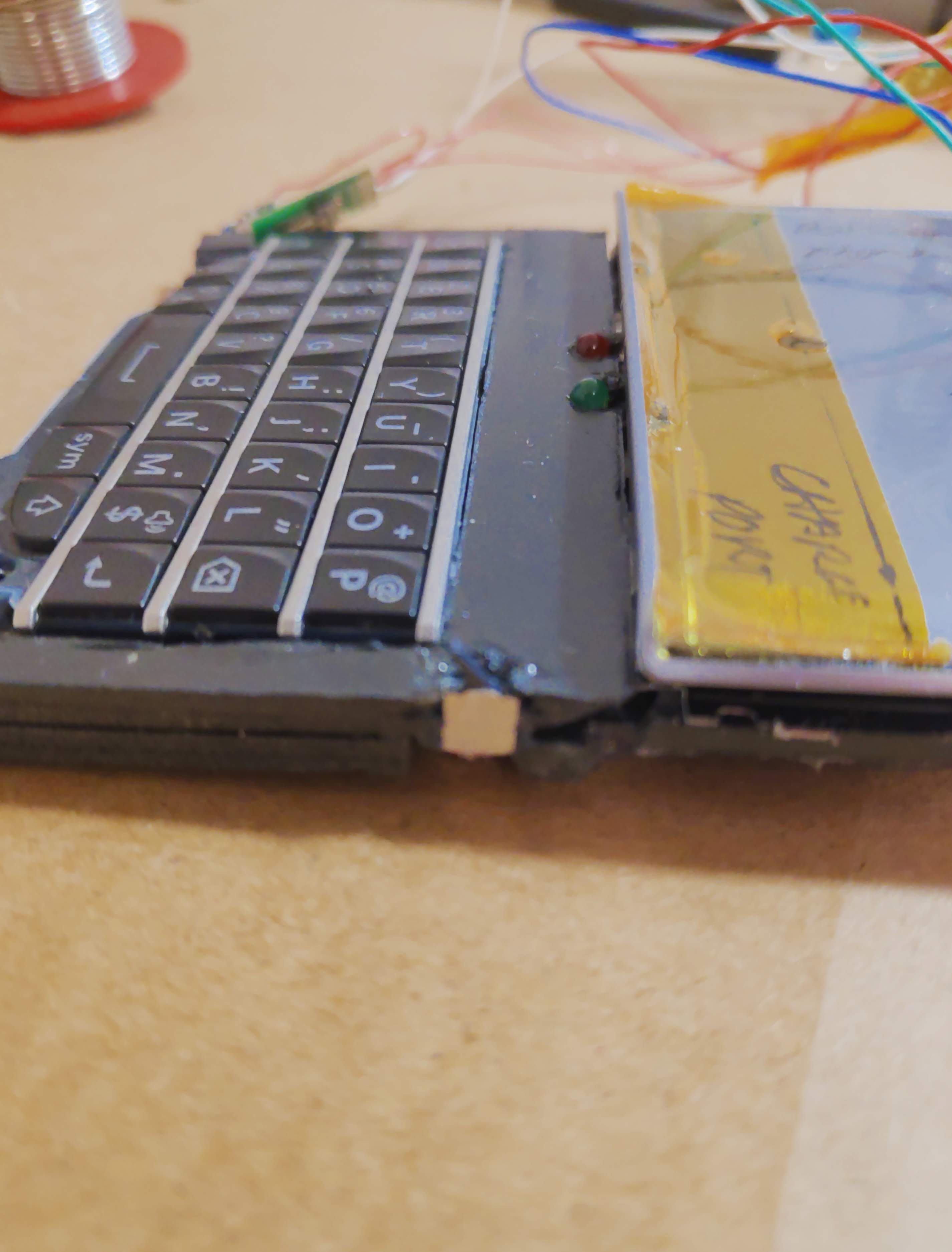
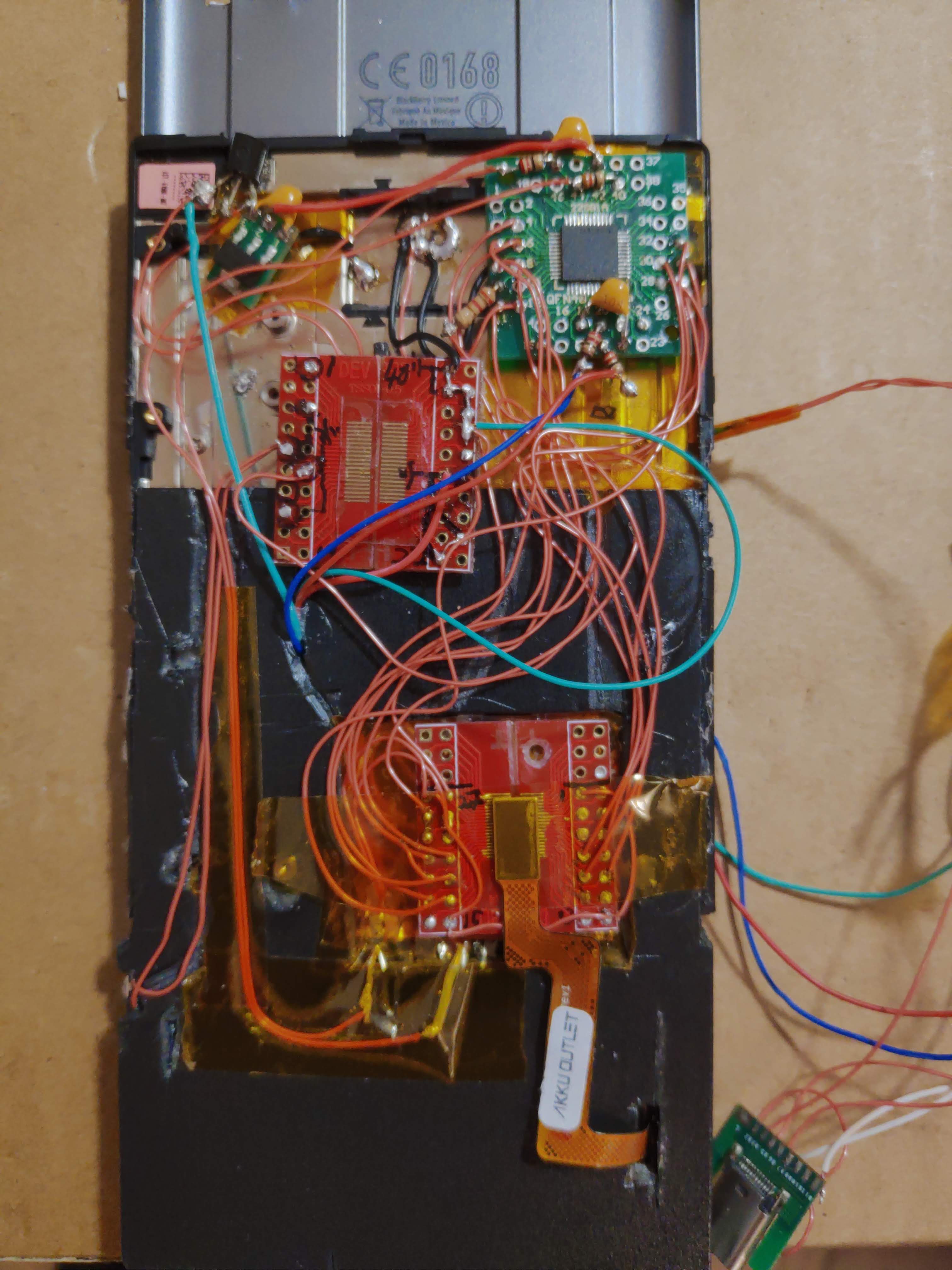
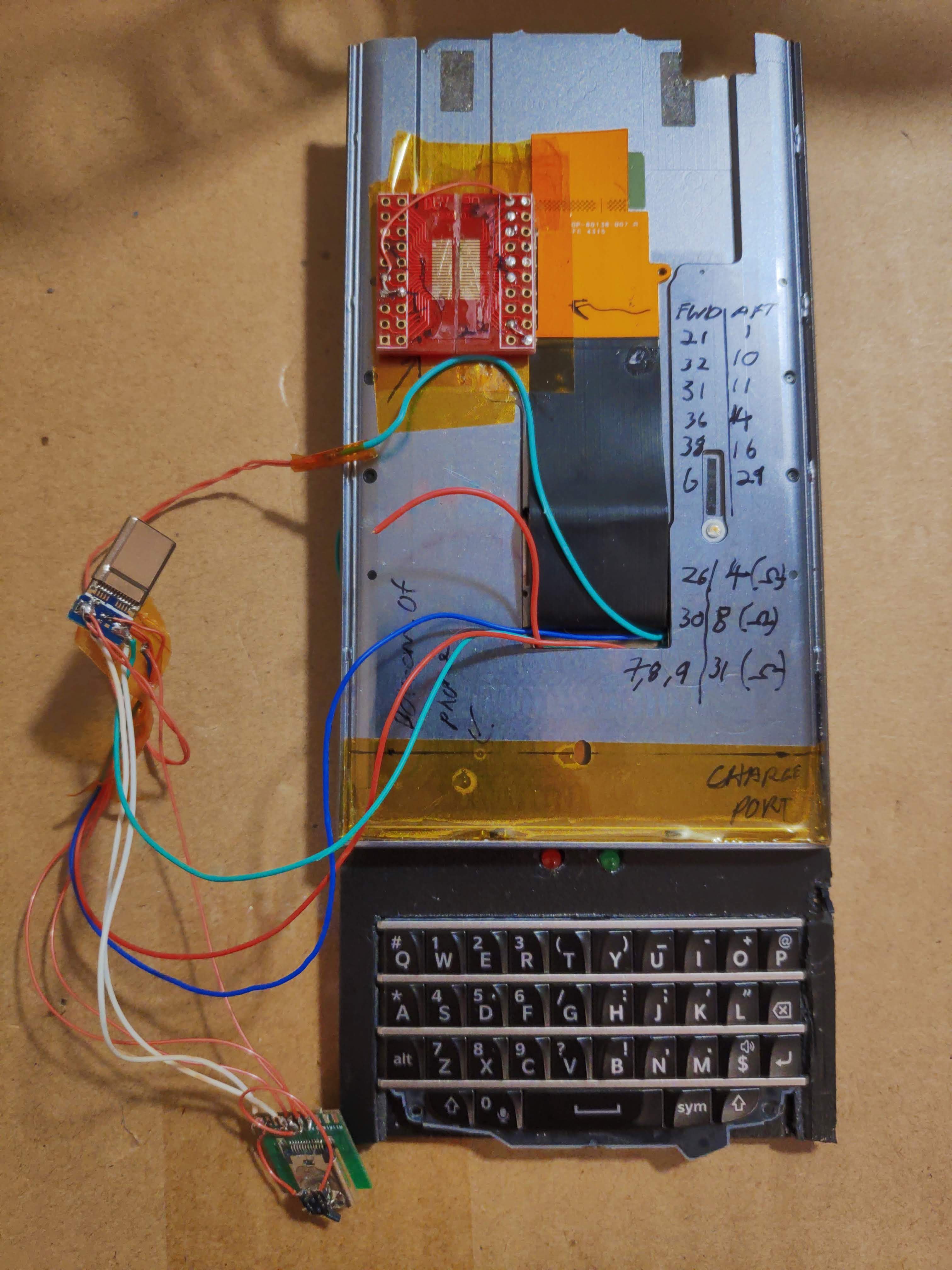
I have modified the sliding chassis to accomodate the Q10 Keyboard and a couple of LED's (FN and Caps) on the lower part. The lower part also accomodates the encoder chip as well as anything else it needs to work (pictured). The rest of the phone (except for the battery) will be mounted on the top part and therefore I tried using the provided ribbon cable, which turned out unsuitable to transfer power and data to the chip and keyboard, so in the end I passed my own wires and hope for the best.
The position of the slider is determined by a small sensor switch on the side (pictured below next to the keyboard). The switch is N.C. and when the slider is closed, it interrupts the power line from USB.
The device also needs to be able to charge the phone without having to disconnect it every time, so I added a USB C port (but only connected Power, ground, D+ and D- ). Another NC sensor switch senses when a charger is connected and disconnects the 5.1KOhm resistor on the Configuration Channel. Without charger, the Switch closes and signals to the phone (thanks to the resistor) that the device is an OTG device. When the charger is connected, the config channel is instead connected to the charging cable which signals that there's a charger available.![]()
![]()
![]()
-
Suggestions? Please let me know!
11/10/2019 at 15:15 • 0 commentsBefore I finalise the test phase. I had a few ideas I would like to include in the final project which make a lot of sense and provide much much more functionality.
1) The SK5126 chip provides 2 pinouts for a PS/2 mouse (1 clock, 1 data) which means that I can simultaneously, without changing the chip, have a small mouse/trackpad allowing for more precise control without having to reach up for the touchscreen. Blackberry's trackpads automatically spring to mind, but upon reading the pinouts online, I don't understand how I can interface this as PS/2 data. If anyone has any information or ideas on how to achieve this, please let me know.
2) As the keyboard occupies the only USB port on the entire phone, I am also thinking of adding a USB hub chip with power support. This will allow me to charge the phone and plug in all sorts of OTG devices without having to unplug the keyboard every time. I think this is relatively easy to achieve and there are many chips out there which facilitate this.
Let me know if you have any other relevant ideas I might try to incorporate into this project. -
Scope of testing and known issues
11/10/2019 at 15:07 • 0 commentsIn its current test-phase, the complete phone and keyboard assy are rather bulky (more precisely it's just too long to fit in any reasonable pocket). Also, the weight on the phone means the whole thing is a bit top heavy and makes typing on it a bit less comfortable. This has been forseen which is why in the final build (the slider) I intend to pull the battery out of the phone and stick the battery right behind the keyboard and then attach a flexible extension cable to the motherboard which allows power to be delivered via the slider mechanism together with D+ and D- cables from the SK5126 chip. The battery connector seems to be a Hirose BM25, which I cannot find from the same shop I bought the BM 14B connector. This is my next task as it is a showstopper until I'm able to provide power to the phone of course.
Another annoying issue comes from the BM14B connector which adapts the keyboard's I/O. due to the extremely small pitch of 0.4mm between each solder, the SK5126 sometimes detects a small amount of voltage between 2 adjacent pins and registers this as a keypress. This problem has been largely mitigated by putting resistors in line with the rows, this also resolves any capacitative effect happening between these extremely close pins. Nonetheless it still manifests itself from time to time and I intend to keep a close eye on it during this test phase. -
Practical test phase
11/10/2019 at 14:48 • 0 commentsAt this point in time, I have installed the keyboard and both PCBs on a sheet of PVC which I used to make a special cover for the phone. This allows me to test out the complete system in a practical manner without having to modify the phone at all. A switch on the side cuts off the power to the chip and will be connected to the slider in the final build to switch on the keyboard only when it is extended. The red and green LED's are indicators for ALT and Caps Lock respectively (they are driven directly by the SK5126 encoder which is another great reason to use that chip).
![]()
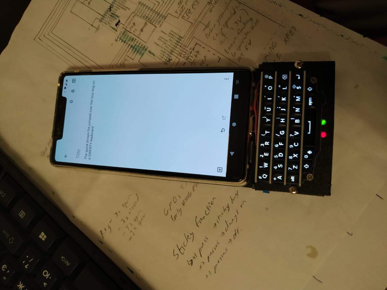
Physical Keyboard for any Android phone
This is my attempt at having an android phone of my choice coupled to a portrait Physical QWERTY keyboard off an old blackberry.