The board I'll be using to drive the megaDisplay is a Nucleo-F446RE, which sports a STM32F446RE chip, operating at a maximum speed of 180mHz, with 512 Kbytes of Flash memory and 128Kbytes of SRAM. Since I'll be sharing the A, B, OE, Latch, & Clock pins for each board, I'll need a total of (8 DR, 1 LAT, 1 CLK, 1 OE, 1 A, & 1B) 13 pins going to the Nucleo.
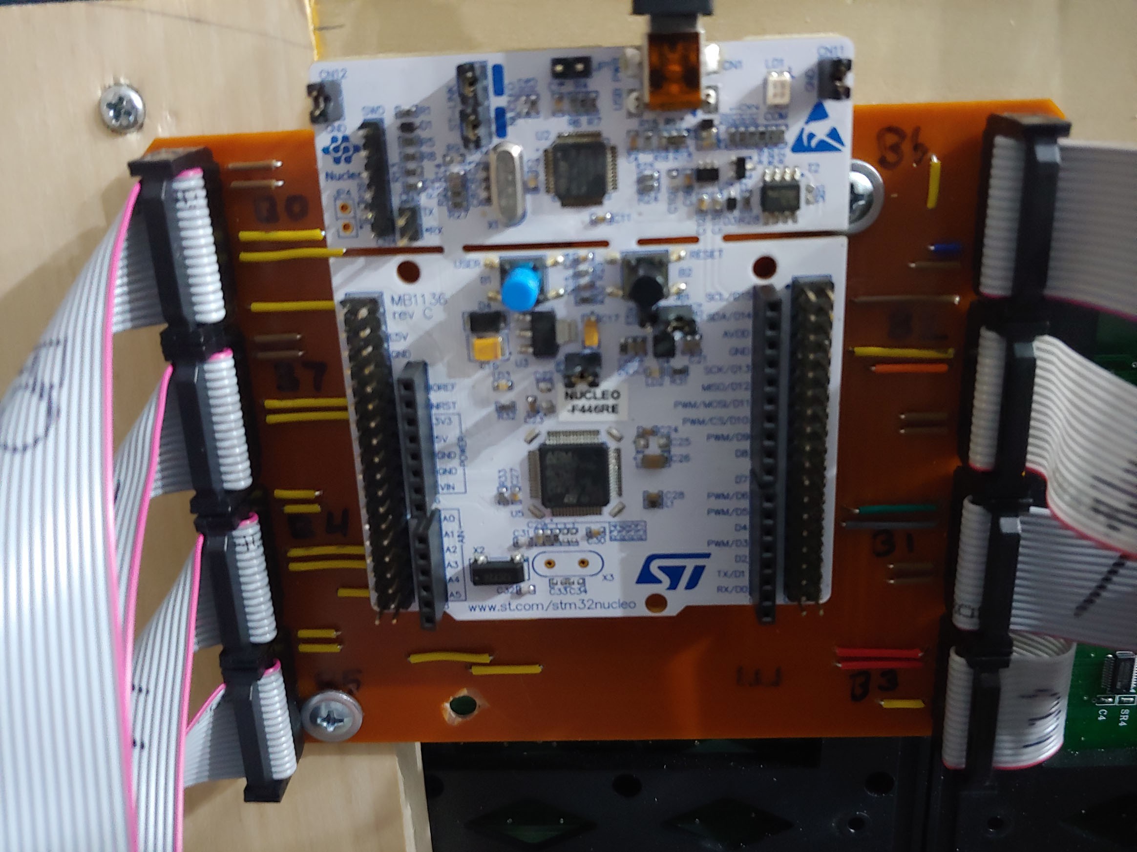
In an attempt to keep things tidy, I've opted to create a quick & crude PCB to accept all the inputs to the panels. I could have ordered a PCB to keep things neater, but this was the quickest solution. Many jumpers abound.
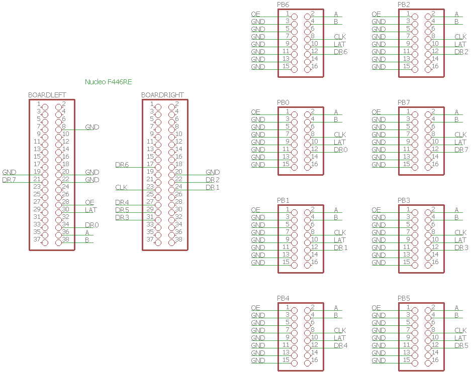
After quickly adding pin headers in Eagle, I compiled the board layout below
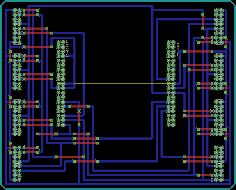
Then it was out to the garage to mill it on the CNC.
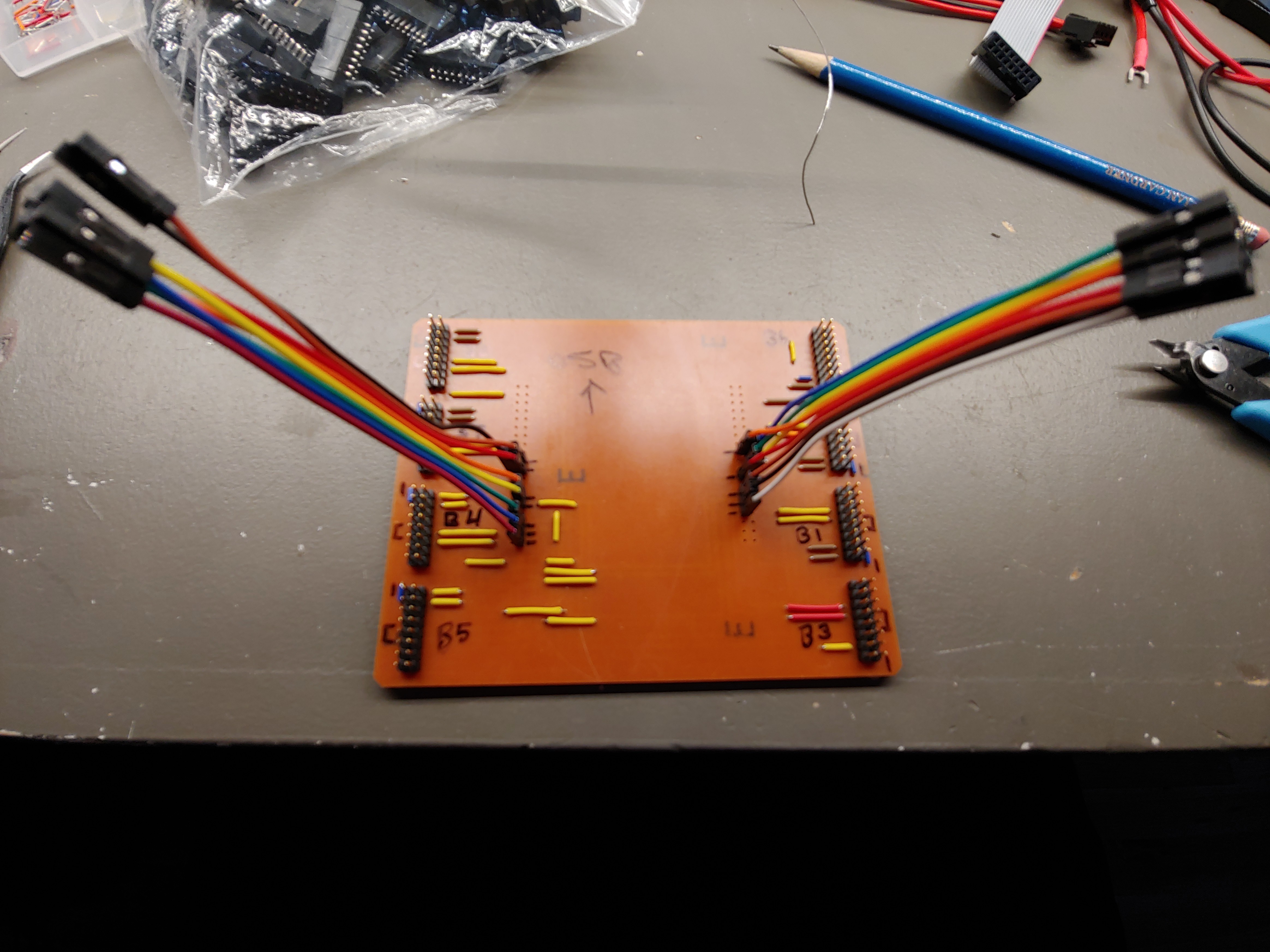
The jumpers were a temporary solution until the female pin headers I ordered came in. The Bx numbers represent the port numbers on the STM32F446RE, which each panel will have its own specific DR pin for the transmission of the display data. Note B0-B7 were used since it's been decided to use DMA for the data transfers.
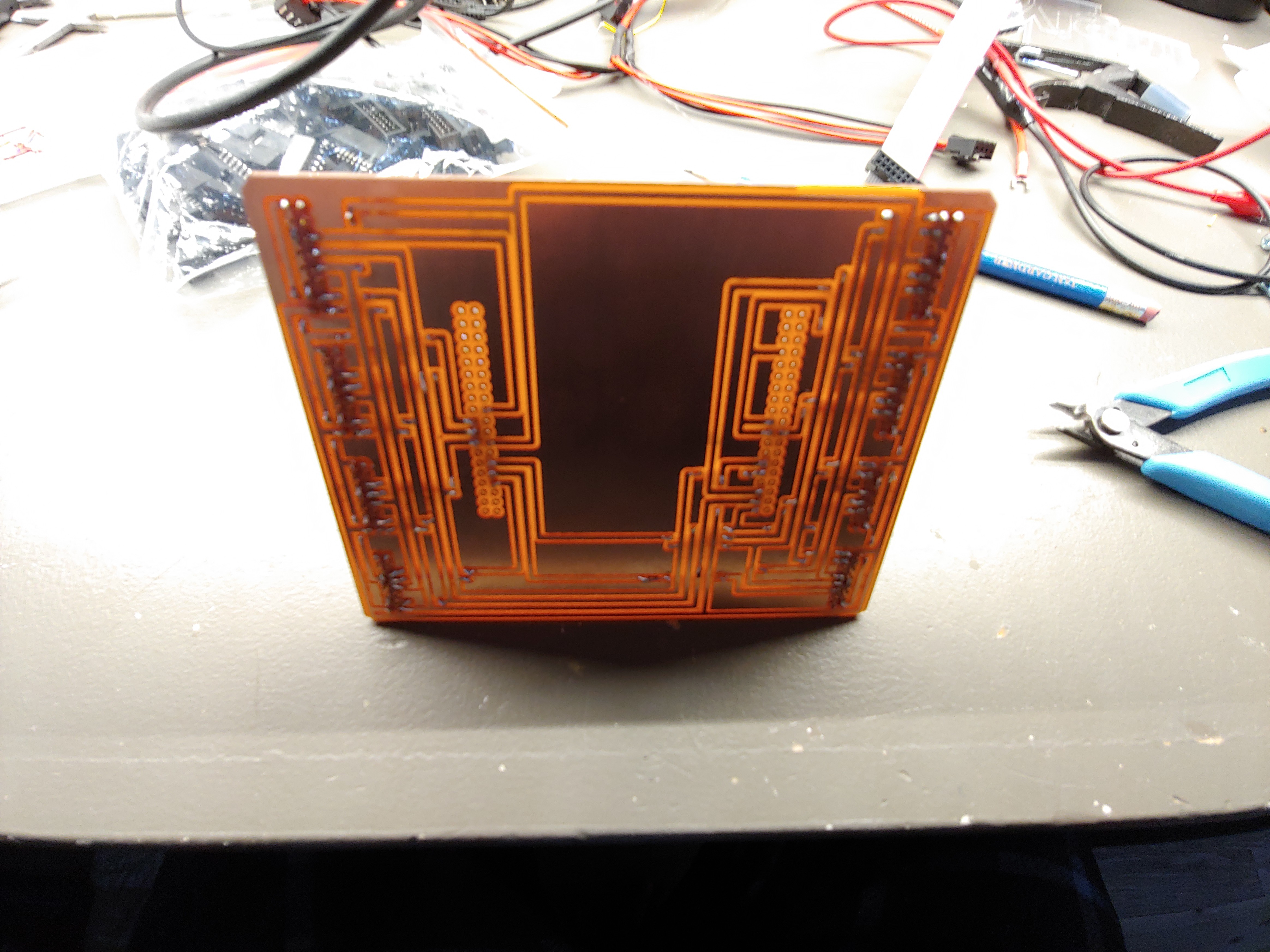
The final board can be seen below with all the jumpers, female pin headers, and Nucleo board installed.
 George Gardner
Discussions
Become a Hackaday.io Member
Create an account to leave a comment. Already have an account? Log In.