-
RetroPie setup
11/17/2019 at 21:10 • 0 commentsI chose to use Raspberry Pi 3B with RetroPie as the permanent source of video signal.
There are several reasons for this:
- I have already used it for my large 55" screen
- it should be small enough to fit in the available space (if not, I can switch to RPi Zero)
- it has GPIO that I might need in the future to connect custom controllers (paddles, spinners, etc.)
The analog audio-video signal is available from 4-pole 3,5mm jack. Until I have everything mounted inside I will use a cable with 3.5mm jack on one side and three cinch connectors on the other side.
It's important to buy correct flavour of such cable. You need the one that has its second ring connected to the ground of cinch connectors.
Consult with helpful documentation where each signal should go.
This is not a place to descibe the installation process of RetroPie, it is already done in great detail in RetroPie documentation. However you should do it with keyboard and HDMI display available. There is too much flicker to do anything in the text mode, even in 80x24 mode. There is a 320x240 mode added to /etc/fb.modes:
# added by RetroPie-Setup - 320x240 mode for emulators
mode "320x240"
    geometry 320 240 320 240 16
    timings 0 0 0 0 0 0 0
endmode
And you can turn it on with fbset:
fbset "320x240"This gives you quite stable 40-column screen. It is good enough for quick edits.
For me the most comfortable way was to setup network and SSH early and to everything through remote console.
There are two changes in the boot configuration to be done.
First thing is to enable composite video mode on RPi. I had to add these lines to /boot/config.txt
# this is to center the screen so that leftmost text column is visible
overscan_left=16
#overscan_right=16
#overscan_top=16
#overscan_bottom=16

# uncomment for composite PAL
sdtv_mode=2
# uncomment for monochrome
sdtv_disable_colourburst=1
# uncomment 1=4:3, 2=14:9, 3=16:9
sdvt_aspect=1
The second thing was needed after installing Kodi. It turned out that the analog audio was slowed down and sounded as if wrong sampling frequency was used.
This line was also needed in /boot/config.txt. It fixed all the audio issues.
audio_pwm_mode=2
With this, my first goal was achieved - I was able to run retro games and youtube using nothing more than a cheap USB joypad.
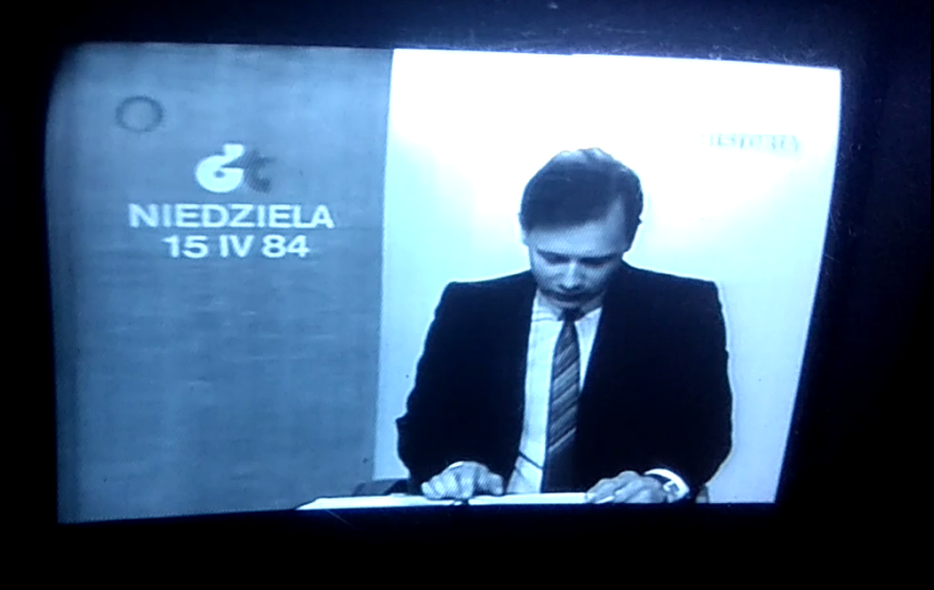
News recordings from deep Cold War (and my kindergarten) times being watched on this device bring so much memories.
Raspberry Pi can run hot when running all these services. The case I'm using has a fan and I wanted it to be sofware-controlled.
This description has the sofware side (script and systemd service) completely covered. Most of the hardware description too. However the ciruit to control the motor there is wrong. It lacks a diode to protect GPIO from currents induced by magnetic fields in the motor. This is the kind of cirtuit you should use. RaspberryPi is no Arduino, but the principle is the same. Just instead of D3 on Arduino connect the transistor's base to GPIO18.
![]()
Instead of 2N2222 you can use other NPN transistors, for example S8050.
Some other things to do using raspi-config:
- configure WiFi
- configure SSH server and add your public keys to /home/pi/.ssh/authorized_keys to be able to login remotely without password
- configure autologin to console, RetroPie emulation station will start from there
Some other things to do using retropie_setup.sh:
- update setup script and all emulators
- install kodi from optional packages (nb. they are not in alphabetical order)
- enable or remove usbromservice and/or samba if you need such things
-
Adding composite input
11/16/2019 at 00:30 • 3 commentsLast time I learned that the TV part of this unit is powered by a single chip that has pretty much everything needed for audio-video decoding from RF signal integrated.
This particular device has AN5151N inside and according to several webpages all I had to do was to cut the trace with video out signal and feed external composite video signal in its place. To make it look like this:
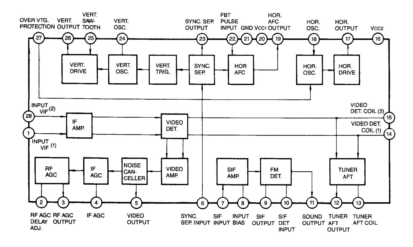
---------- more ----------Here is the block diagram from a helpful datasheet:
![]()
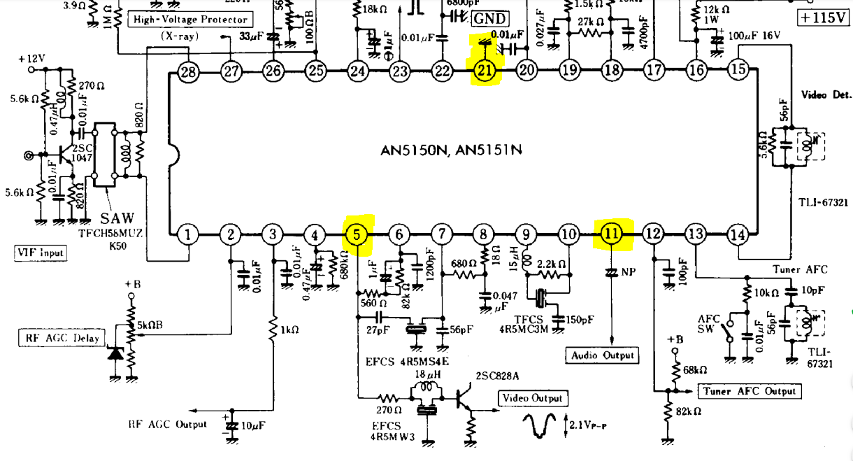
We are interested in pins: 5 - video output, 11 - audio output and 21 - ground. Browsing through forums about hacking CRT TV sets I learned a bit about various ways how they were constructed. For instance some of them had different grounds: signal ground and chasis ground. Tying external signal ground to wrong place could result in damage to one/both devices (in worst case) or degraded signal (best case).
Fortunately this modern design had external power supply or battery power options and I checked in various points that there was only one GND across whole control board.
This is the typical application cirtuit from the datasheet:
There is a common ground from pin 21. Audio from pin 11 goes through capacitor to an amplifier and speaker. Video signal from pin 5 goes through a transistor to amplify signal from 0-1V (composite) to video output feed.
I don't have schematic, nor service manual for this particular unit. I simply cut the trace near pin 5 and connected cinch socket center pin to the side of the trace that goes further into TV circuitry.
My easy way to cut the trace and not to damage anything nearby was to use a sharp pointed knife and slowly scrape a line perpendicular to the trace. Afterwards I confirmed with continuity meter that the connection was indeed cut.
Once cinch socket was connected and with an old Atari 2600 clone (with composite video mod) plugged in. I powered on the TV. I have waited several seconds for the tube to warm up and... nothing happened.
I have reconnected the signal from pin 5 and saw TV snow back, so it wasn't like I broke the device in the process.
Minutes passed while I was puzzling about it.
It turned out that while disassembling the case I turned brightness way too low to have anything visible on the (mostly dark) initial game on that console.
My advice is to be patient and turn brightness and VHOLD potentiometers very very slowly.
The next thing to do was to connect audio. I have traced the signal coming out of pin 11 and with the unit turned on I tried various places on the way of audio signal until I got good sound from the speaker. Here I didn't cut any traces because when TV is not tuned to a station the tuner is muted.
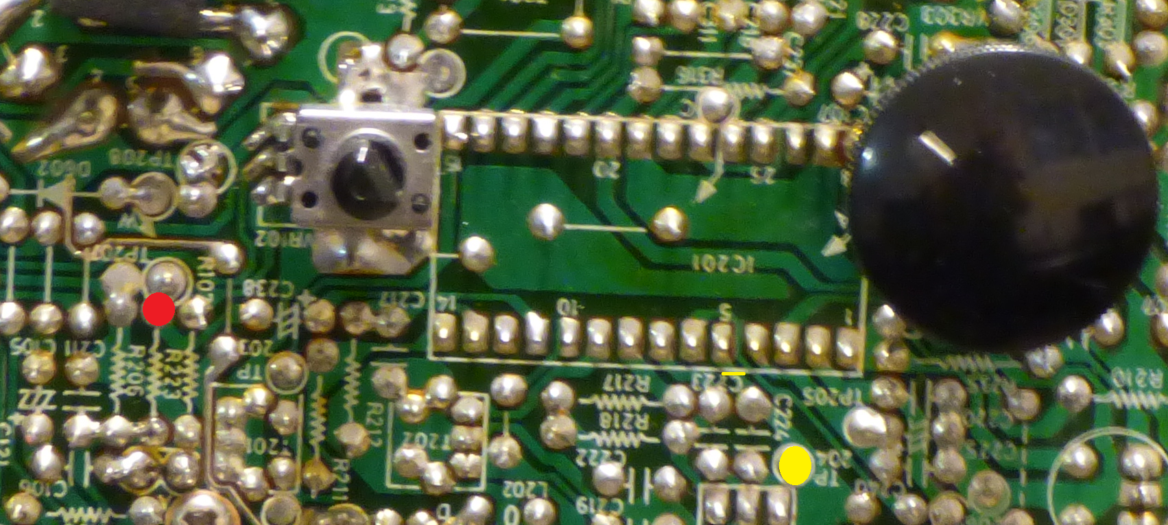
![]()
Video trace was cut on the yellow line just next to pin 5 and a new input feed was soldered to the yellow spot, a test point.
Audio signal comes through a wire soldered to the red spot.
The last thing to correct was to improve the geometry of the picture. Again, a schematic would be very helpful. I was able to find correct trimmer on the board. I could then move the picture to the right to make it more centered.
This improved the image. Unfortunately I don't see how to move it in vertical direction or how to control the width/height and correct for barrel distortion.
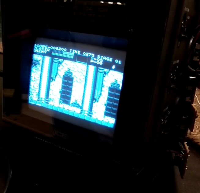
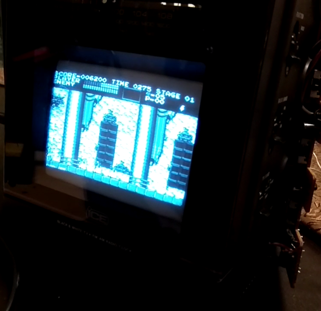
Anyway it looks gorgeous. Here is a screenshot of Castlevania from NES from an emulator running on Raspberry Pi.
More about it next time.
-
What's inside?
11/13/2019 at 22:45 • 0 commentsSince the unit arrived in such good condition I took great care to disassemble it without damaging the soft plastic or scratching the front transparent cover in the process.
There are two screws on the top back and two more under the front.
After removing them it's easy to take out the top cover and it should be easy to separate the shell into two halves. But there was a clear obstruction on one side and I didn't want to break anything by using force.
After several minutes of trying, it turned out that it was the big wheel for tuning that has been keeping the parts together. After removing that obstacle, I was finally able to open the device. The cables are long enough that I could open it completely without the need of disconnecting anything.
![]() ---------- more ----------
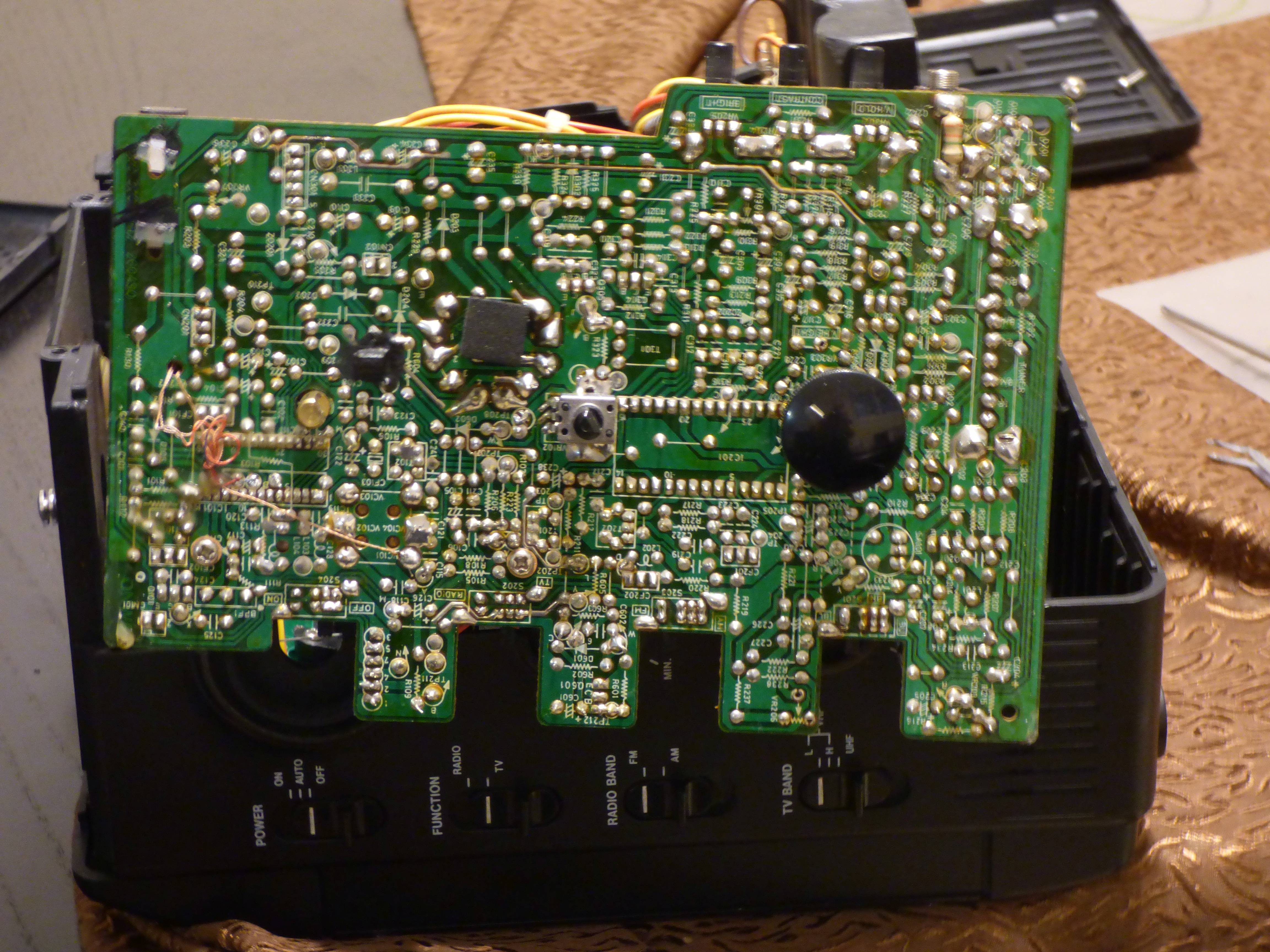
---------- more ----------There is one control board responsible for radio and TV. Power supply is completely separated in the back part of the enclosure. The third PCB is responsible for the alarm clock and is quite independent from the other two. It even has its own AA battery.
There is one more thing that I would have known about, had I read carefully the Radio Museum page about the device: it's actually battery operated. The battery compartment is at the bottom and occupies whole length and width. I'm not going to use batteries at all, but this gives me some room for any extra electronics, like Raspberry Pi.
I didn't disconnect any leads, so it was quite difficult to make a good photo of the inside.
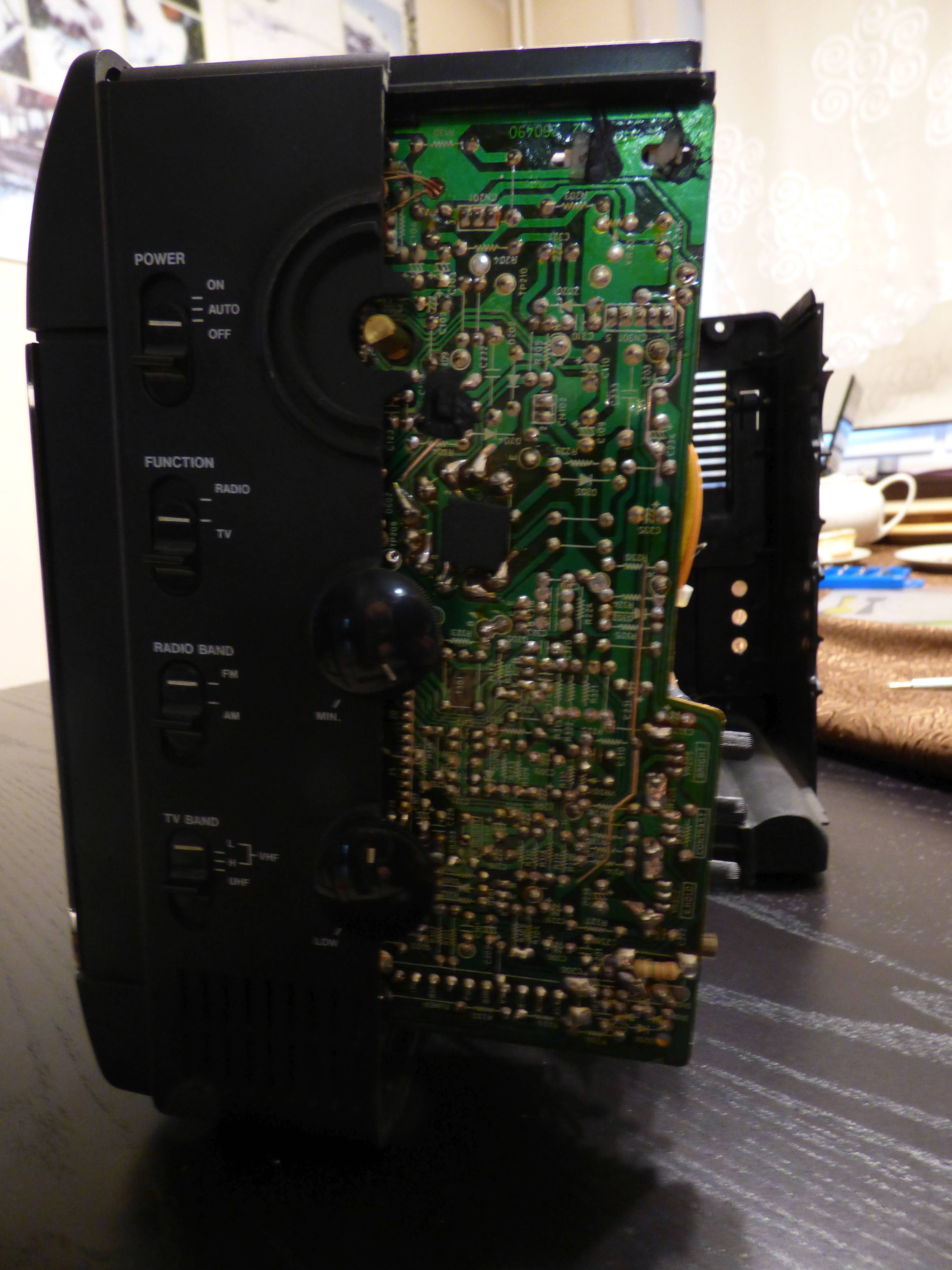
![]()
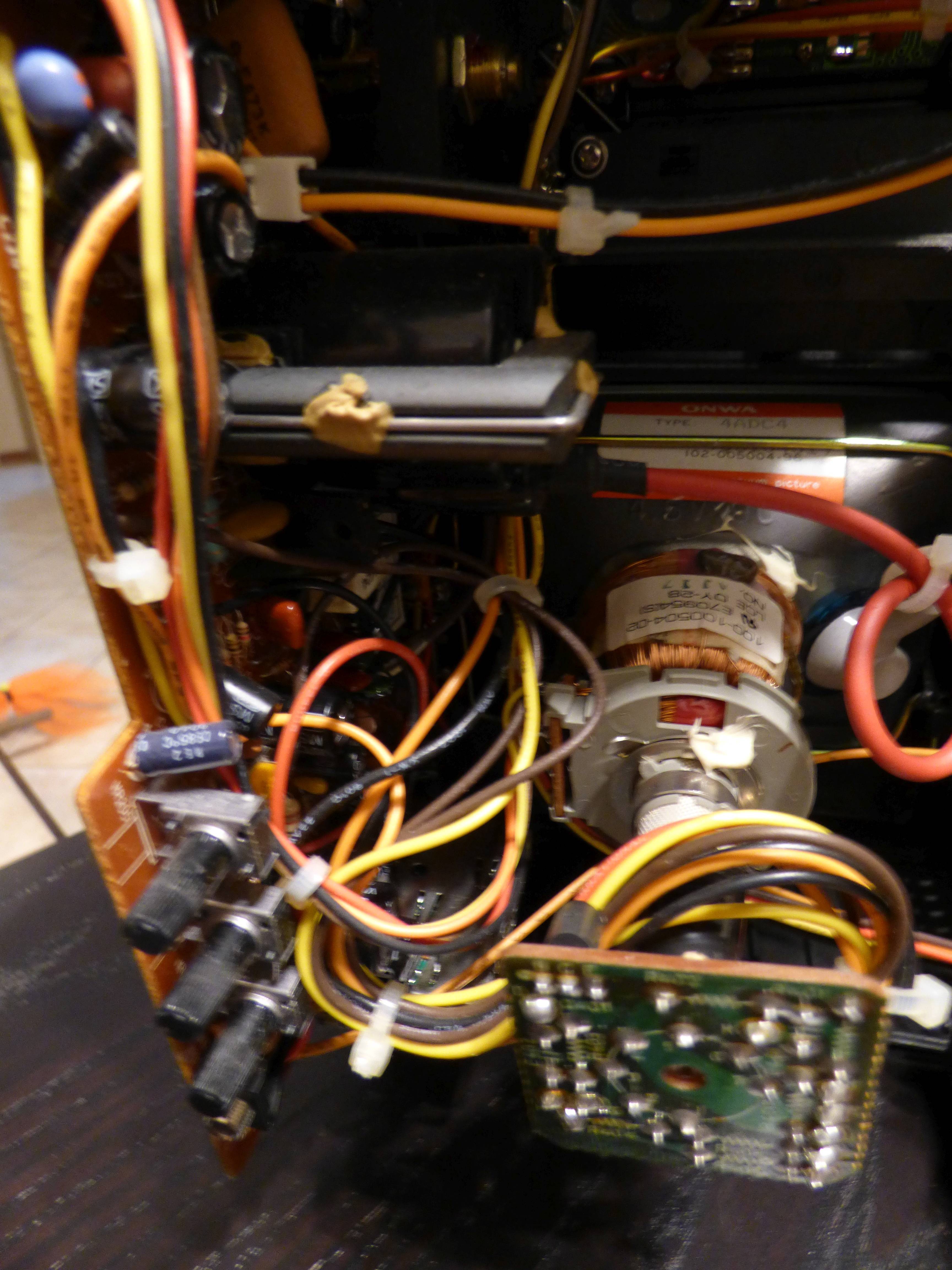
The TV and radio control circuit is on a single sided board. There is a lot of information on the silkscreen, including test points.
![]()
Too bad I was not able to find neither schematic, service manual or even user manual for that thing.
When putting everything back together it's important to set the sliding switches into correct positions.
I have done some research while waiting for the package to come and I was happy to see more or less what I was expecting: RF modulator in a can and a single largish DIL chip as the heart of the PCB.
Black and white TV coming from this era used one kind or another of integrated video IF processor. There were several clones: CD5151GP, AN5151N and KA2915. With relief I found that this particular TV has AN5151N inside - the only one which has datasheet with legible typical application circuit.
More on that next time.
-
What is this thing?
11/12/2019 at 23:33 • 0 commentsI started this project in late October. First few log entries will cover what has already happened.
The item arrived in late October 2019. I was very suprised by its excellent condition. It was spotlessly clean, with no accumulated dust or grease. Only few scratches here and there. As if it was almost never used, even though it came without original packaging.
Seller was truthful - it was fully functional and in working condition.
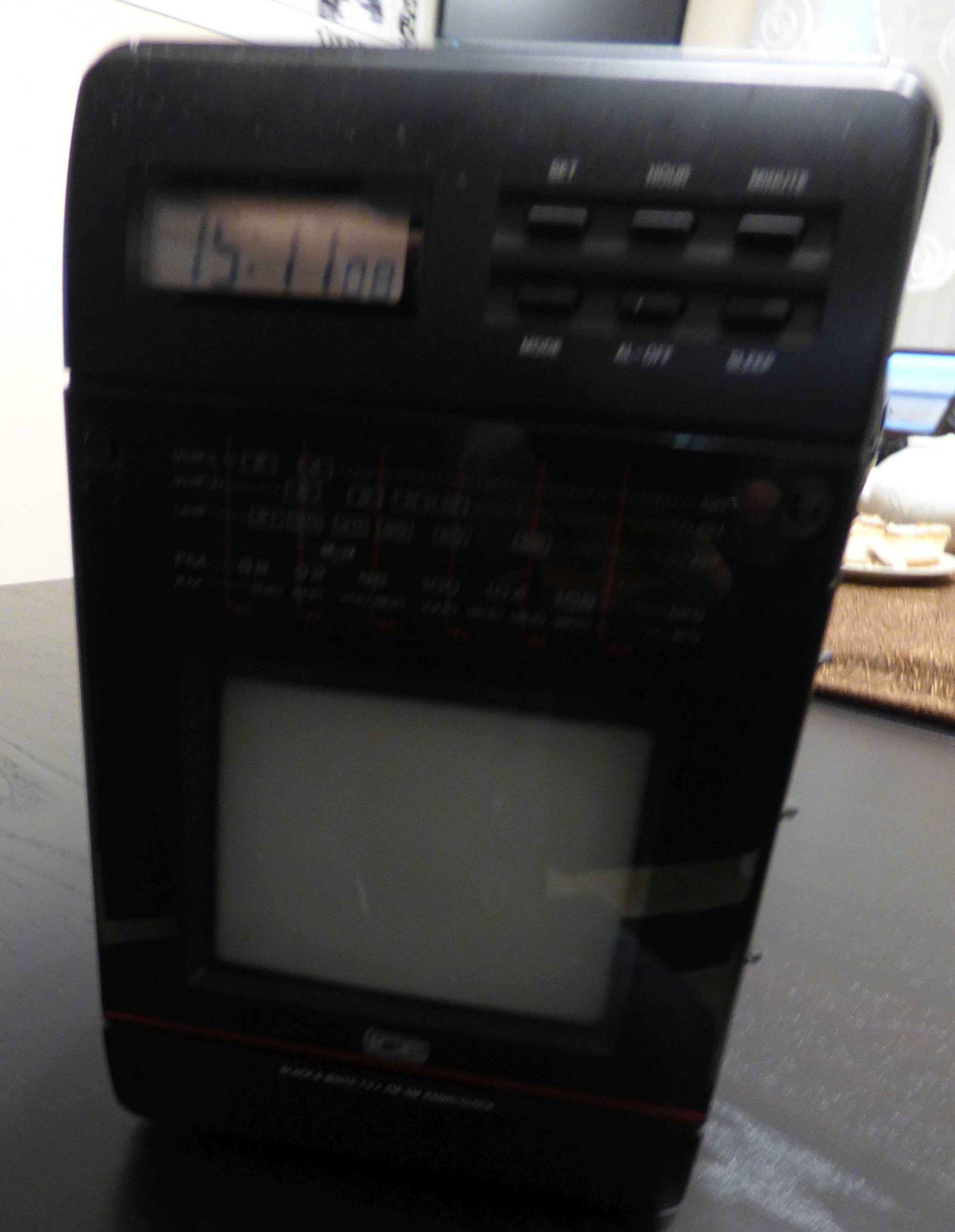
On the front there is a 4,5" black and white CRT tube. There is a scale for radio and analogue TV tuning and set of six buttons to set time and alarm. I don't have any user manual, but seller was kind enough to set correct time for me before shipping.
![]() ---------- more ----------
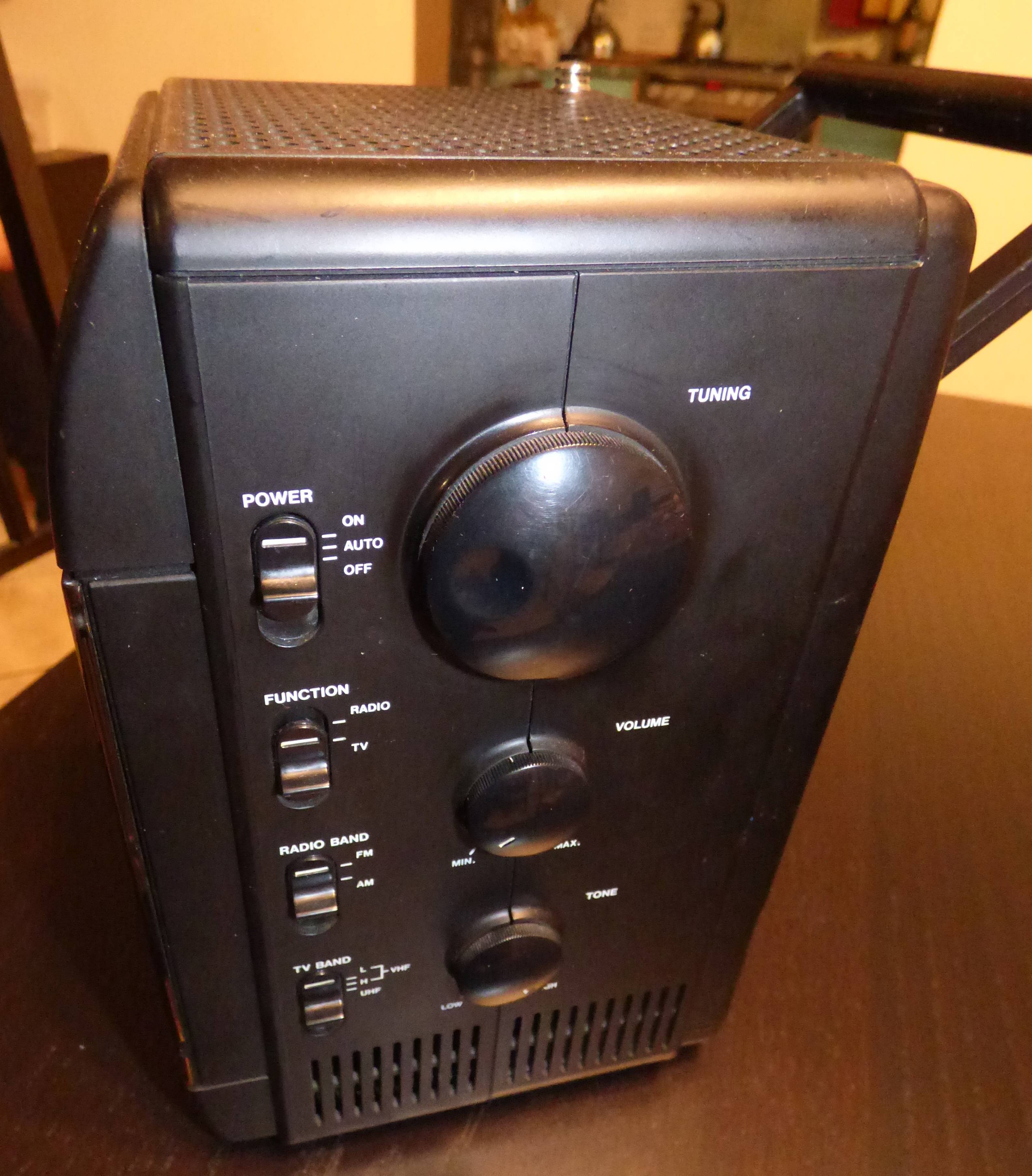
---------- more ----------On the side there are potentiometers for volume and tone, as well as a wheel for tuning both radio and TV at once. So if you tune into a FM station and then want to go back to TV you would have to find the station again. There are also sliding switches to choose the power mode, TV or radio function and bands. The speaker is on the top and in one corner of the top cover a telescope antenna is hidden.
![]()
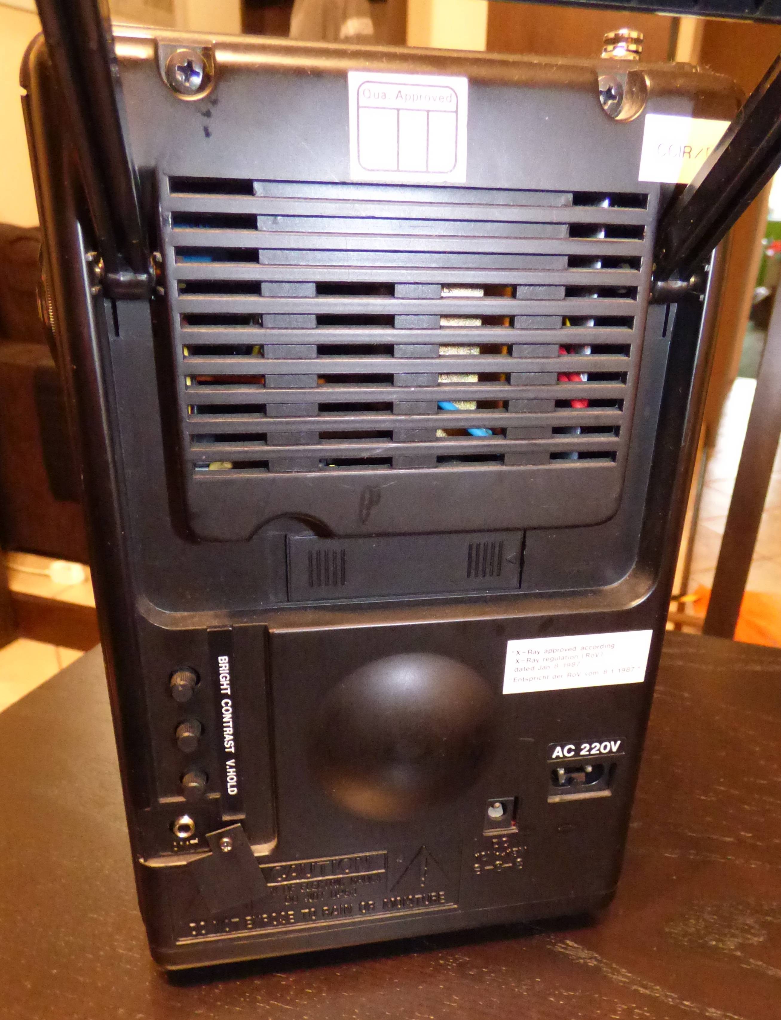
On the back we have brightness/contrast and VHOLD potentiometers. The device is powered either by 220VAC or 12-15VDC. The power consumption is supposed to be 20W. Under a little cover there is also a 3.5mm jack for external antenna.
![]()
So there it is. I was quickly able to check that radio works. I confirmed that the external antenna jack sleeve is connected to the ground and that I could just use stereo audio cable 3.5mm jack to cinch to connect it with C64 or Atari 65XE. This way I confirmed that TV bands and tuning selection also works.
I'm sorry I don't have any pictures of that. The image was as expected through RF modulation-demodulation - a little bit fuzzy and noisy. There is quite large distortion of the geometry, but I don't know yet how to correct that.
But it was glorious on that little CRT. This amount of contrast between almost total black and very bright white is something that I completely forgot about after years of using LCD monitors.
As you see there is no composite video input. I will have to add it somehow.
But first - how to open this thing and what's inside?
Portable CRT TV with Retropie+Kodi combo
So I bought this old portable black & white TV. What next?
 Maciej Witkowiak
