 Frank
FrankThe design goals for revision 4 was to achieve dual-axis control. A second motor controller was added together with a 16 dual-color LED row for Zenith angle display and positioning. A TFT display should improve data feedback, and onboard solar position calculation called for a means to aquire location information, adding a GPS receiver.
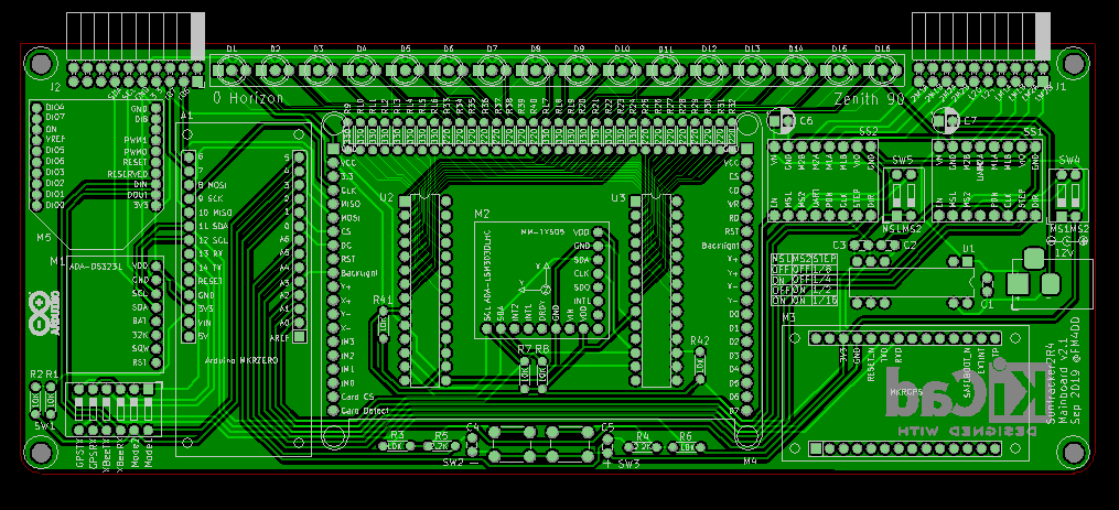
Routing the components is going to max out all available pins of the Arduino MKRZero. 4 pins were freed up by moving the StepStick speed control to external DIP switches. So far the default speed was sufficient and I had no need to control it from the MCU.
It was also a challenge to maintain the intended mainboard space. For manufacturing cost, the PCB should be dual-layer only. The solution was to stack components, and use the space below the TFT to place the magnetometer and zenith row IO expander IC without a socket. They are sufficiently cheap to make this trade-off here. Finally, I had to move the displayboard connectors further out, I think I can compensate on the displayboard for the extra connector offset.
For space and simplicity, I planned to route the I2C bus to the displaybard, and handle the port expansion there. This saved the biggest space and reduced the connector size.
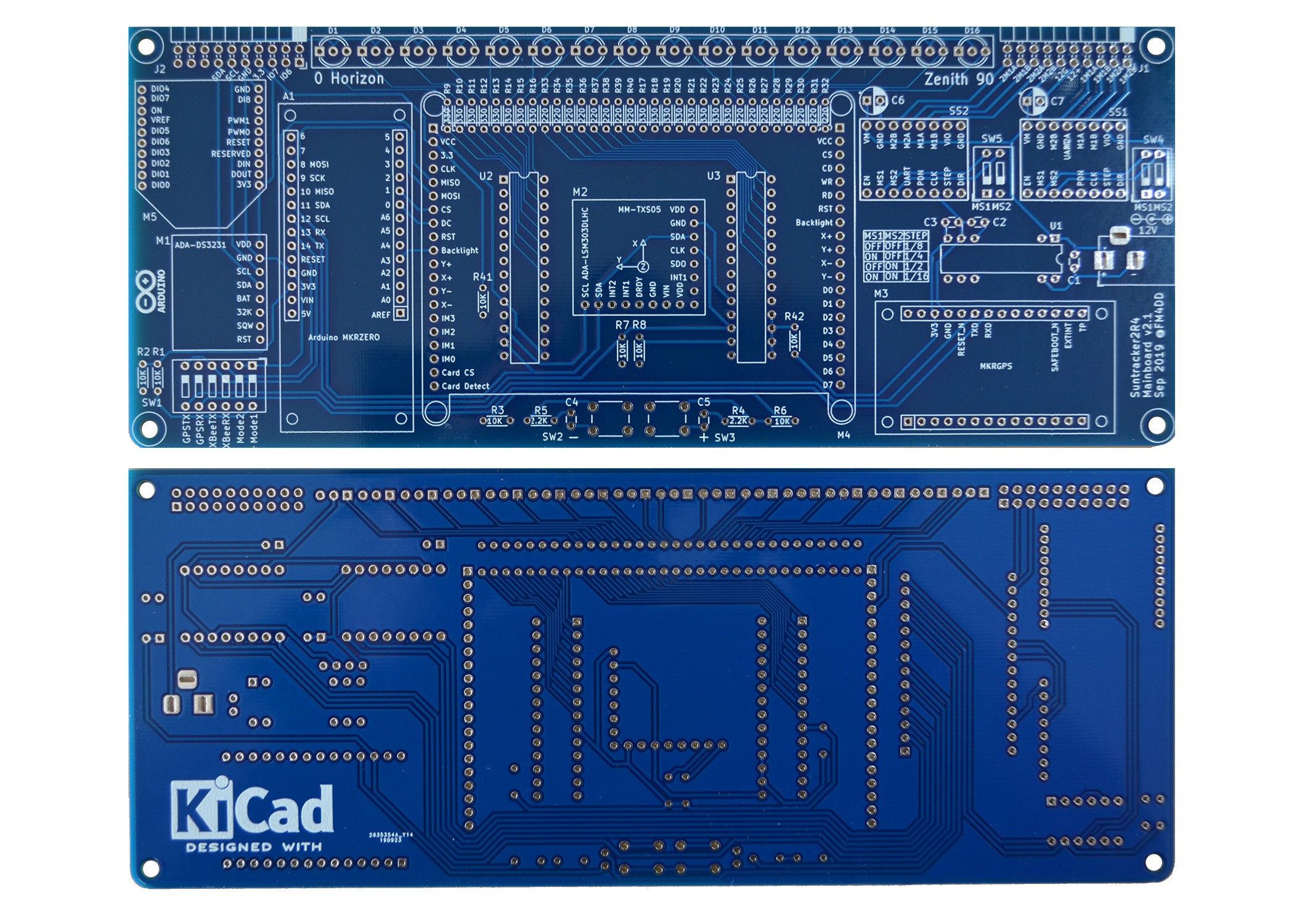
For PCB manufacturing I wanted to try the blue color instead of standard green, and the result looks neat.
Another first for me is to drop pre-fabricated power converter modules, and make use of the Texas Instruments DC/DC converter chip DCR01 for the first time. Its a risky move since I haven't even tested them yet. The specs look great, and the packaging in a DIP IC format is just perfect.
Discussions
Become a Hackaday.io Member
Create an account to leave a comment. Already have an account? Log In.