-
Test Setup
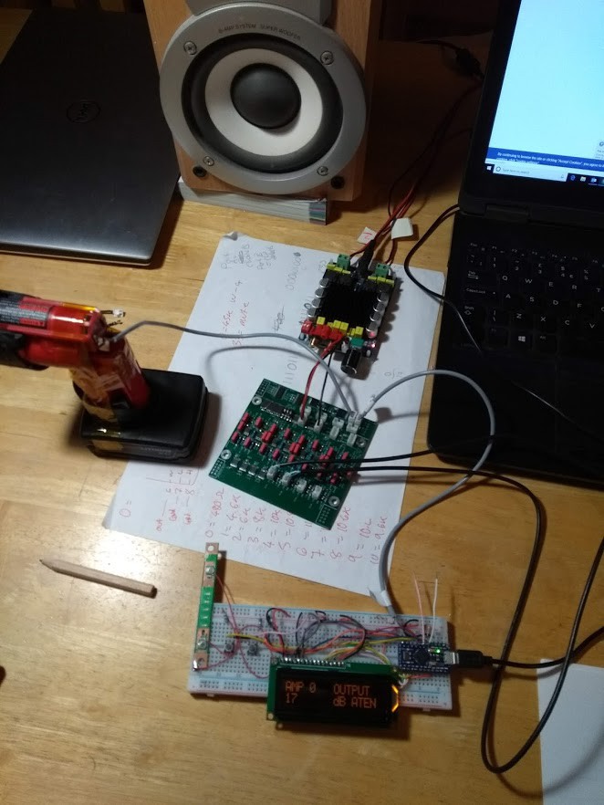
11/18/2019 at 17:34 • 0 commentsAn Arduino was used to send I2C commands to a single board for testing. The Ardunio has 4 buttons and an 2 line LCD. You will be able to work out the connection details quite easily from the sketch.
Here is the setup running from 2 12V drill batteries for the dual supply:
![]()
Above: Test setup of a single output channel. The sketch allows the selection of the input of the amp (zone) and the attenuation of the input. 33 = off and amp disabled. 0 = maximum volume.
I discovered that the digital pots take 20ms to be ready to receive data from the CE being flipped. The majority of the sketch is a basic task handler which writes any changes required to the audio settings into a 32 bit value which is stored in a buffer array. The task handler then sends these every 20ms.
The interface is clunky but was only for testing. In the final setup I will probably create a web based interface on a raspberry pi that will talk to the boards.
Whole House Amplifier
I2C Audio Switcher & Volume Control for up to 16 Bi-Amped zones
 Rory
Rory