Andy
Andy-
First Data Visualization
01/03/2020 at 16:42 • 0 commentsI've set up an integration with TTN (The Things Network) and Tago. I don't know that much about Tago, nor do I endorse it in any way. It simply was the easiest to setup so I can show what was one of my goals of this project: sensor data on the cloud.
Here's a link to the public view of the dashboard I've setup for the project. Right now, it's basic and just shows some battery data. I need to update the device (I'm away now) to output the current and charge %, but voltage data is real
-
Project updates
01/03/2020 at 15:29 • 0 commentsCouple of project updates:
Hackaday has officially closed the Take Flight with Feather contest, they have said that they will notify winners near the end of January, so I'll continue on working away at it.
I'm still working on getting a useful demo up and running. I've currently got the LoRaMac-node code taking battery voltages, I'm just working on setting up the TTN based backend and data visualization part.
I've made another small change to the PCB. Offically it is at REV C0. Initially, I thought it would be cool to have the hard secure element on the board as I really haven't seen anyone working on it. Much later in the design process, I came across the MCCI Catena 4612. One of my first goes at a LoRaWAN Feather was very similar to this board using the same module. I had trouble with toaster oven solder reflow yields, so I opted for a discrete solution like what I have now. On any note, they incorporate an FRAM device which can store provisioning and frame counters without any worry of EEPROM wear out or data retention loss. Looking at the SOIC8 versions of the ATECC608A crypto chip and really any I2C FRAM device, one can see that the supply pins and the I2C pins are all in the same locations. The remaining pins are NC for the ATECC608A and are the address pins for the FRAM (similar to any 24LCXX EEPROM). So by simplying grounding the A0-A2 and WP pins on the PCB footprint, you could fit an FRAM chip or the crypto chip as you see fit.
I have a couple more almost built boards and I'll probably build a few with FRAM on them and bodge wire the pins to ground. That way I could maybe put together some code for the hard secure element and maybe some that utilizes the FRAM.
I also still intend to test out USB on the boards. USB would be useful mostly for charging and firmware updating but maybe some debugging/diagnostic data could be useful as well.
I also updated some files here on the project page to reflect some of the project progress.
I'd love to hear from anyone interested in the project as where to go next!
-
LoRaMac-node running!
12/26/2019 at 05:31 • 0 commentsWith the hardware mostly squared away, it's time to finally see if the LoRaMac-node reference implementation from Semtech will run.
The overall approach will be to add in the LoRaWAN-Feather as a "board" in the reference implementation. This will require adding my own board support package. Since my board is based on the STM32L073 and SX1262 it's really just a matter of cobbling together existing pieces of the Semtech code.
First, I'll fork the repo. I'll pretty much be using the code from the B-L072Z-LRWAN1 board. The B-L072Z-LRWAN1 is based on the Murata CMWX1ZZABZ-091. This is an all in one LoRaWAN solution. By using this BSP, I won't have to deal with the concepts of shields and Nucleo boards. But since my boards are running STM32L073's, I'll borrow some parts from the NucleoL073 board support package. I'll also edit the CMakeLists.txt files to allow for my new platform. Once I get the new board support package to build and link, I'll move on to adding in the required app examples for my board support package. So far, all the apps with my board build (they are all copies of the B-L072Z-LRWAN1 apps with the references to extra LEDs removed), but only the classA app has been tested.
So, if you have the hardware you should be able to clone my fork of the official LoRaMac-node repo and flash it to the board and have it up and running to a gateway of your choice. If you have a gateway up and running with TTN, it should look a little something like this:
![]()
This shows my custom Raspberry Pi/RAK2245 gateway receiving uplink messages from both of the LoRaWAN-Feathers that are running.
Up next would be to create a somewhat useful example that maybe has the two LoRaWAN-Feathers uploading the battery data acquired by the on-board fuel gauge.
-
PCB Change
12/21/2019 at 18:29 • 0 commentsNoticed while reading over the STC3100 datasheets that I made a hardware layout mistake. The first revision boards will function, but accuracy is reduced. According to AN3395 Section 4, Number 2. The GND pin of the STC3100 should be directly connected to the CG- pin of the current sense resistor and not through the ground plane. The PCB layout around the STC3100 is pretty open, so the change was easily made. The board version has been bumped to B0 and all fab files updated in the GitHub repo. I also changed R16 and R17 to be DNP by default.
-
Testing the STC3100 on the LoRaWAN Feather Board
12/15/2019 at 20:09 • 0 commentsSo I put together a simple project using the *.ioc file that I created for the Feather board, CubeMX and the driver I just put together and the results are good.
First up is to get rid of the FreeRTOS calls:
//buf = pvPortMalloc((size_t)(ByteCount + 1));
buf = malloc((size_t)(ByteCount + 1));

//vPortFree(buf);
free(buf);
and replace them with the standard library calls.
Also, of course the I2C handle changes too:
halRet = HAL_I2C_Master_Transmit(&hi2c3, STC3100_SLAVE_ADDRESS_8BIT, buf, ByteCount+1, HAL_MAX_DELAY);
becomes
halRet = HAL_I2C_Master_Transmit(&hi2c1, STC3100_SLAVE_ADDRESS_8BIT, buf, ByteCount+1, HAL_MAX_DELAY);
Here's the relavent portions from main.c
/* USER CODE BEGIN 2 */
  printf("MCU Init Complete\r\n");
  assert_param( STC3100_Startup() == STC3100_OK );
  printf("Fuel Gauge Init Complete\r\n");
  /* USER CODE END 2 */
and
while (1)
  {
    /* USER CODE END WHILE */

    /* USER CODE BEGIN 3 */
	  HAL_GPIO_TogglePin(USER_LED_GPIO_Port, USER_LED_Pin);

	  assert_param(ReadBatteryData() == STC3100_OK);

	  printf("Battery Data (%d):\r\n", s16_BattCounter);
	  printf("\tVoltage(mV)\t%d\r\n", s16_BattVoltage);
	  printf("\tCurrent(mA)\t%d\r\n", s16_BattCurrent);
	  printf("\tTemp(0.1degC)\t%d\r\n", s16_BattTemperature);
	  printf("\tCapacity(mAh)\t%d\r\n", s16_BattChargeCount);

	  HAL_Delay(1000);
  }
Again, pretty simple. I wrap the STC3100 library calls in assert statements for debugging purposes. That way if there is an error, it ends up in the assert failed handler and I have some basic debugging clues left behind.
Anyway the result runs (capture from PuTTY):
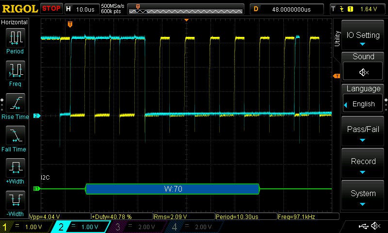
Battery Data (29691):
        Voltage(mV)     4186
        Current(mA)     -1
        Temp(0.1degC)   213
        Capacity(mAh)   401
Battery Data (29693):
        Voltage(mV)     4186
        Current(mA)     -1
        Temp(0.1degC)   213
        Capacity(mAh)   401
Battery Data (29695):
        Voltage(mV)     4186
        Current(mA)     -1
        Temp(0.1degC)   213
        Capacity(mAh)   401
Battery Data (29697):
        Voltage(mV)     4186
        Current(mA)     -1
        Temp(0.1degC)   213
        Capacity(mAh)   401
and the I2C waveforms look good on the scope:
![]()
![]()
So I'm happy about the hardware and software around the fuel gauge IC. I don't plan at the moment to look at the crypto chip. Instead, I'll switch now testing the radio or getting a whole LoRaWAN project up and going on it.
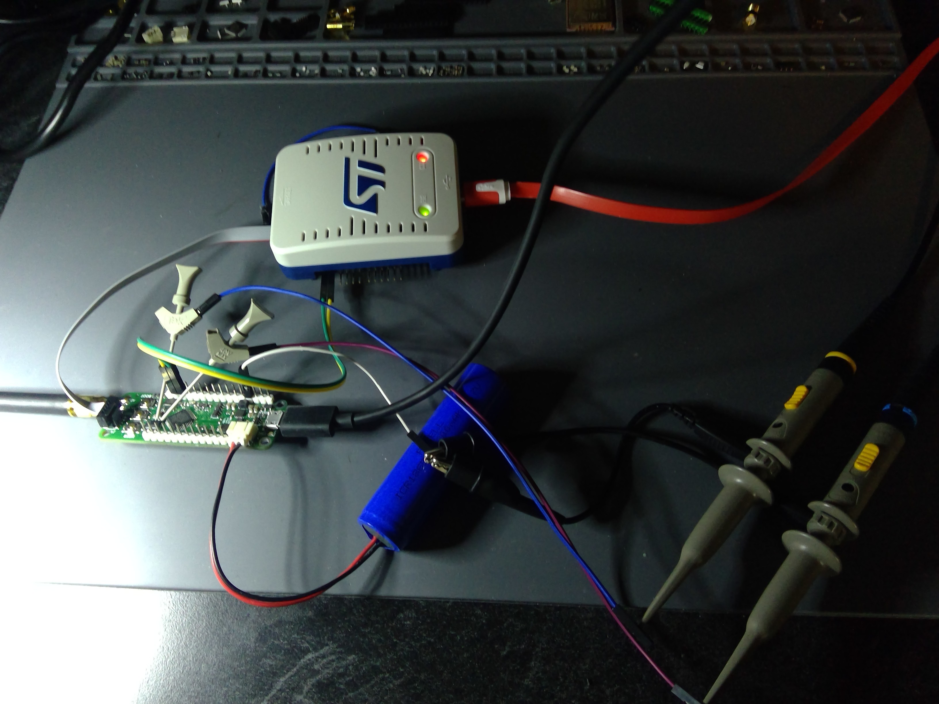
For reference, here's my debug setup:
![]()
I've got the Feather board with the Tek probes grabbing on to the I2C pins of the crypto chip (the only place I can easily grab the I2C bus), the ST-LINKV3, a battery and the scope probes off to the side. The yellow and green wires are the LPUART connected back to the VCP pins that give me a Virtual COM Port from the ST-LINKV3. The black USB cable was charging the battery
-
More STC3100
12/15/2019 at 19:48 • 0 commentsNow onto the STC3100_Read method:
int STC3100_Read(unsigned char ByteCount, unsigned char RegisterAddr , unsigned char * RxBuffer)
{
	HAL_StatusTypeDef halRet = HAL_OK;

	if(!RxBuffer)
	{
		return( halRet = HAL_ERROR);
	}

	halRet = HAL_I2C_Master_Transmit(&hi2c3, STC3100_SLAVE_ADDRESS_8BIT, &RegisterAddr, 1, HAL_MAX_DELAY);

	if(halRet != HAL_OK)
	{
		return halRet;
	}

	halRet = HAL_I2C_Master_Receive(&hi2c3, STC3100_SLAVE_ADDRESS_8BIT, RxBuffer, ByteCount, HAL_MAX_DELAY);

	if(halRet != HAL_OK)
	{
		return halRet;
	}

	return halRet;
}
Pretty simple and straightforward stuff.
The code works on the Charger 2 Click and I get back readings that seem to look just fine. Now onto adapting it run on the LoRaWAN Feather board.
-
More Testing...
12/15/2019 at 16:32 • 0 commentsTime now to take a look at the STC3100 fuel gauge IC. As a starting point, I'll be using this library on GitHub. I'm not sure if it is an official ST repository/account, but the driver looks useable. It just needs an I2C implementation added to it. I've pulled the 4 required files out and put them into my own repository. To initially test the code, I'm using the Charger 2 Click from Mikroe in my Clicker 2. The Clicker 2 uses an STM32F4 but that will allow me to reuse the code on the STM32L0 on the LoRaWAN Feather thanks to CubeMX. The STM32F4 project is based on FreeRTOS and CubeMX. Of course, FreeRTOS isn't required as we'll see on the code that runs on the Feather. Here are the I2C methods I wrote to talk to the chip:
First, STC3100_Write
int STC3100_Write(unsigned char ByteCount, unsigned char RegisterAddr , unsigned char * TxBuffer) { HAL_StatusTypeDef halRet = HAL_OK; uint8_t *buf; if(ByteCount == 0) { return(halRet = HAL_ERROR); } buf = pvPortMalloc((size_t)(ByteCount + 1)); if(!buf) { return(halRet = HAL_ERROR); } buf[0] = RegisterAddr; for(int i = 0; i < ByteCount; i++) { buf[i+1] = TxBuffer[i]; } halRet = HAL_I2C_Master_Transmit(&hi2c3, STC3100_SLAVE_ADDRESS_8BIT, buf, ByteCount+1, HAL_MAX_DELAY); if(halRet != HAL_OK) { return halRet; } vPortFree(buf); return halRet; } -
Forgot to show you the bottom
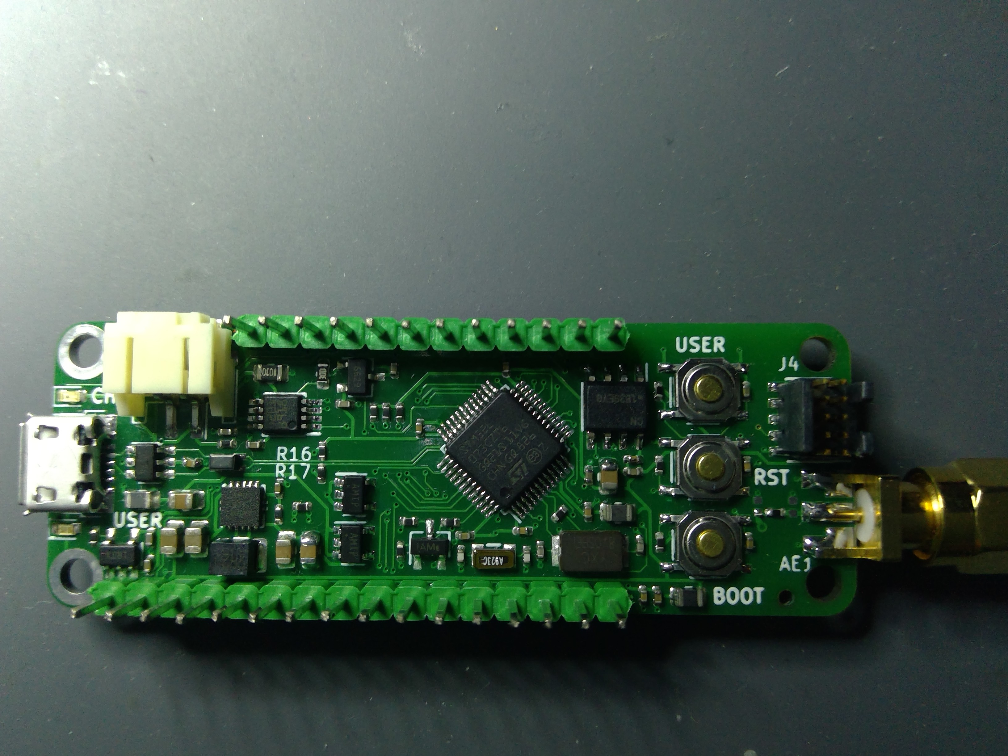
12/04/2019 at 23:08 • 0 commentsJust realized I didn't snap a photo of the underside with the radio module. So here is yet another crappy photo
![]()
-
Update!
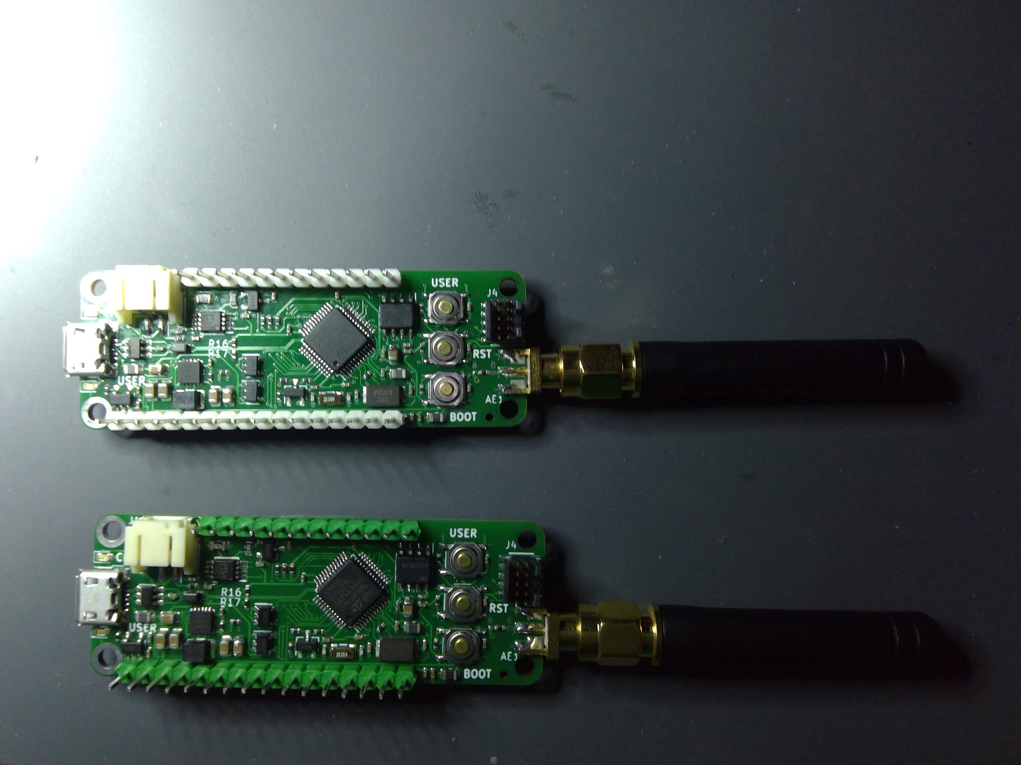
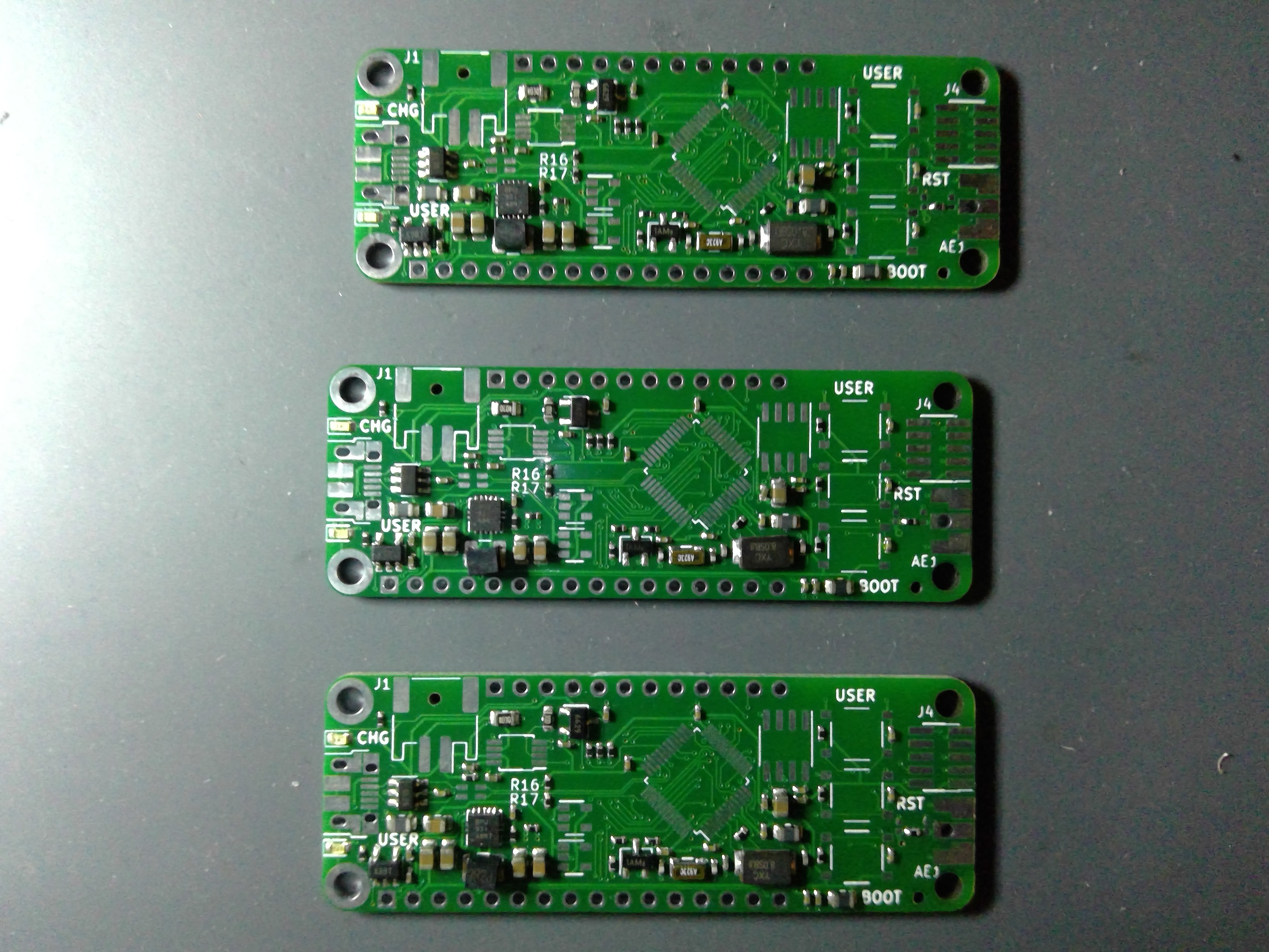
12/04/2019 at 23:02 • 0 commentsUpdate on the project after the holiday! I got in the semi-assembled boards from JLCPCB. I'm very happy with the quality and speed of the assembly process. The boards look great:
![]() Sorry for my crappy photography skills. JLC doesn't have any connectors in their SMT assembly library which is strange, so they aren't assembled. The three user buttons were supposed to be assembled, but that was an error on my part. I did not select a part on the BOM selection step of the process. Oh well, Digikey to the rescue. The rest of the parts were either not in stock or not available for assembly. Time to get out my iron!
Sorry for my crappy photography skills. JLC doesn't have any connectors in their SMT assembly library which is strange, so they aren't assembled. The three user buttons were supposed to be assembled, but that was an error on my part. I did not select a part on the BOM selection step of the process. Oh well, Digikey to the rescue. The rest of the parts were either not in stock or not available for assembly. Time to get out my iron!![]()
![]()
I decided to start with two so that I can run the LoRaWAN stack's ping pong application as a test as well as get them connected to my Raspbery Pi based LoRaWAN gateway for testing. However, some initial testing is in order first!
To date, I've done a basic power on test using the 3.3V from a bench supply, the battery and 5V via USB and all function as designed. This tells me that my DC-DC is working, as is the rest of the power system. Battery charging also works.
I loaded up a simple blinky application and it runs, proving my SWD and crystal circuits are working. Only snafu there is that the LED is green instead of red! Probably an error on my end again, but a minor one.
Only issue I've noticed so far is that I populated R16 and R17. With the STM32 USB FS Phy, pullups on the D+/D- line aren't required, but I wanted to have the pads there just in case. I'll have to desolder those when it comes time to test the USB.
My next step is to write some basic code to test the battery fuel gauge and at least make sure I can communicate with the crypto coprocessor.
So far, off to a good start!
-
PCBs
11/19/2019 at 14:15 • 0 commentsLooks like the missing parts were errors on my end (go figure). The common mode filter for USB was out of stock and I didn't select a suitable replacement (which was available). The switches were in the CPL file, but not the BOM so they won't be placed. I've ordered the balance of parts from Digikey and should be able to finish off the boards by hand. As of this morning the PCBs are almost done with production. I've updated the schematic with part numbers from Digikey for all the parts.


 Sorry for my crappy photography skills. JLC doesn't have any connectors in their SMT assembly library which is strange, so they aren't assembled. The three user buttons were supposed to be assembled, but that was an error on my part. I did not select a part on the BOM selection step of the process. Oh well, Digikey to the rescue. The rest of the parts were either not in stock or not available for assembly. Time to get out my iron!