Alexis
-
Motor’s First Turns
06/13/2021 at 18:06 • 0 commentsIn order to determine how much current the motor pulls, we had to make it turn with a load and monitor its consumption. The perfect load was in hand, we took last year’s LED pannel, as ours will have approximatly the same weight and dimension, therefore giving a good estimate on our power consumption.
We took the same brushless motor as last year, a MEGA Acn 22/20/4. Which is connected to a motor controller, a EZRUN Max 10 SCT. It is rated to be able to supply up to 120A, so we could not take this value to size our power supply. So I tested the whole system to see how much would it drain.
First I had to understand how the controller worked. The datasheet is not very helpful, as it only says to put a RC receiver on the input wires. So I emulated one with an arduino. A RC receiver uses PPM signal, and is waiting for a 1 to 2ms pulse every 20ms. 1ms being the command for neutral throttle and 2ms for full throttle.
In order for the motor controller to acknowledge that you sent a RC signanl, you need to start by sending neutral throttle command. It is a security measure to prevent the motor turning on when it has just been plugged in.
After came my first attempt with no load on the motor. It ran fine and the controller pulled around 1.5 to 2A. Then Itried with last year’s pannel, and it would not start rotating at the lowest speed, or be all jittery. My teacher told me that last year, in order to start the rotation, they sent a high speed command and backed down to lower one when it started. I did so and now the whole structure is rotating.
![]()
LED pannel rotating. Slowed down 16 times. I filmed it slow motion to be able to determine the speed it’s rotating at. With the almost lowest setting it is rotating just under 20rps. At this speed it is pulling 4A under 12V. I tried making it rotate faster, so I just left it at the high speed command I use to start it up. I did not go well. Leaving a high speed command made the controller pull more than 20A because it was unable to match the requested speed. So the power outlet shut down.
In order to get the whole system to high speed I proceeded gradually. Letting it establish at low speed for seconds and increasing the speed slowly.
An other problem rose up, at low speed it was not that wobbly. The structure was only a bit unstable. At high speed it is a whole different story. The metal structure would move around the table and produce more noise. We will have to be very carefull about the placement of the component and plan to be able to put masses and the lower rotating part to balance the whole structure, as you would on a car tire.
-
DC-DC converters
06/13/2021 at 18:05 • 0 commentsOn the mobile part of our system, we need to convert 12V to 5V and 3.3V. Each conversion has its constraints:
- Both need to be able to start slowly enough in order to limit the inrush current from the 12V rail to a minimum.
- The 5V rail needs to withstand the switch of its output current from almost 0A to 9A in a few dozens of nanoseconds, corresponding to the activation of a new LED scan line.
- The 3.3V rail needs to be able to start quickly enough for the FPGA to startup properly.
I looked at the TI modules for our application. I chose the LMZ22005 for the 12V->3.3V@5A conversion, and the LMZ12010 for the 12V->5V@10A conversion because of the low count of external components required to make the design work. TI has an online tool (WEBECH Power Designer) allowing us to select a converter, choose the external components according to our output target voltage and current constraints and simulate its behavior (they have another downloadable program called Switcher Pro, but it is outdated and doesn’t have recent modules). It helped me confirm that the default 1.6ms of soft start time of the modules I chose was enough to limit the inrush current.
![]()
Inrush current at startup The second step is to check if we meet the FPGA requirements. The Cyclone V Device Handbook Volume I indicates the relationship between the rise time of the 3.3V rail and the Power On Reset (POR) delay. The Cyclone V Device Datasheet states that there are two POR delays that we can select: a fast one, between 4 and 12 ms and a standard one, between 100 and 300ms. In conclusion, the soft start time is quick enough for our FPGA to start properly.
Speaking of inrush current, we are in the worst case scenario for the FPGA inrush current at startup because we are powering all the banks with the same power rail (i.e. at the same time). But it translates to at most 2.92A for a maximum duration of 200µs (see table 10-1 of the Cyclone V Device Handbook Volume I), which is inside of our estimated power envelop.
Lastly, we need to be able to have very quick changes in current drawn on our 5V rail. The TI tool is a little buggy and depending on the component I choose in my design, the simulation can have voltage spikes (in the hundreds of volts, unrelated to the current being drawn). So I couldn’t simulate with higher output capacitor than the one selected by default (540µF), which would have probably reduced the output voltage variations (here: -4%, +2%). The current variation has been based on the rise and fall times of our LED drivers (TLC5957), which are respectively 40 and 16ns. The other interest of this simulation is the current actually used from the 12V rail: up to 12A.
![]()
Load transient However, I wonder if it wouldn’t be easier for the schematics to use the same module twice.
-
From architecturing to schematics
06/13/2021 at 18:04 • 0 commentsArchitecturing
Last Wednesday, we finished discussing about architecture. We made some major changes.
First, we discovered that we couldn’t use the TLC59582. We made some assumptions about the way ES-PWM works that aren’t specified in the Datasheet. We thought we could control the PWM width over one segment using the 8 MSB, and we could send a VSYNC signal in the middle of the PWM period. This would have resulted in an 8bit PWM, which is ideal. Without these assumptions, we only have a 12bit PWM which period is too long compared to the display time of a single point.
After checking a lot of LED drivers and PWM generators, I couldn’t find anything suitable except for the TLC5957. Most drivers are either using 12-bits PWM, or using an 8-bits PWM but with really insufficient data rates. The TLC5957 has the advantage of being configurable from 9 to 14 bits (resulting in small enough PWM period when used with 9 or 10 bits), and with a really high data rate.
We also had to think about how to configure the Wifi. After thinking about a bunch of scenarii, we went with the simplest solution since we are running late. We will use a button on the mobile part used to turn the Wifi module into AP mode. It will also start a web server that can be used to configure the Wifi AP to connect to.
Finally, and again for sake of simplicity, we decided that the fixed and mobile parts will not communicate since it’s not strictly necessary. The fixed part will use a switch to start and stop the motor, and a photosensor to get feedback on the motor’s speed. Since the motor is controlled with 5V logics, and we do not longer need Wifi or Bluetooth, we will use an Arduino Micro instead of the ESP32. It can be powered using 12V, provides a regulated 5V/1A pin, and PWM capable 5V GPIOs.
Schematics
I’m beginning to work on the schematics. For know, I designed one LED panel including its driver and column multiplexing.
![]()
-
More voxelizing and simulation
06/13/2021 at 18:03 • 0 commentsFor the past week, we have been discussing a lot the components we will have. We mainly focused on the power supply, our photosensor(s), our Wi-Fi module(s) and our LED driver.
For more information about our hardware decisions, you may look at Ambroise, Guillaume and Baptiste’s posts.
In my last post, I showed you how I created a vtkUnstructuredGrid that fits our display system. The past week, I managed to extract geometrical data and color from the meshes in Blender and I tried a lot of different ways to fit the mesh geometrical data into my grid representing our cylinder.
The voxelizing algorithm takes in input a list of colored meshes and outputs an image that is the slices of the scene containing the meshes.
As we have a 40×30 LED panel and 256 steps per rotation, I decided to output one frame as a 1200×256 image, where every row is a different slice of our scene and the 1200 pixels in each row represent the RGB components of the LEDs, going from left to right, top to bottom. This image is currently saved as .bmp and .raw (which is basically BMP without the header) files.
I created multiple scenes to test out our algorithm. Below, you can see the result of voxelizing different kind of meshes. The first picture will be the model of the mesh I tried to voxelize. The second one will be the output of the algorithm, which is the 1200×256 reprensenting the LED configurations at each angle. The third one is how the LED configurations should appear to our eyes with our real system (it is a simulator, written by Guillaume using Processing — it works pretty well!)
Voxelization results
Colored cube
![]()
Original cube model ![]()
Voxelizing algorithm output ![]()
Simulation of the colored cube display Green cylinder
![]()
Green cylinder model with 32 faces ![]()
Voxelizing algorithm output of green cylinder ![]()
Simulation of the green cylinder display Bi-colored Sphere
![]()
Bi-colored sphere model ![]()
Voxelizing algorithm output of bi-colored sphere ![]()
Simulation of the bi-colored sphere display Colored text
![]()
Colored text model ![]()
Voxelizing algorithm output of colored text ![]()
Simulation of the colored text display Results interpretation
As we can see, our voxelizing algorithm is not perfect but we can easily recognize the original meshes. Let’s see the pros and cons of the current algorithm.
Pros:
- A cylinder of diameter 4:3 and a height of 1 is perfectly mapped to our system.
- We can easily recognize shapes and texts although it does not feel perfectly aligned.
- The raw output is well-fit for our system : reading sequentially the output file gives the different slices of a frame, in the correct order.
- The algorithm can basically voxelize any colored mesh scene.
- Blender has an animation framework and it should not be too much work to make a video with our algorithm : by simply voxelizing every frame and displaying them one after the other, we can get a 3D video.
Cons:
- The algorithm is slow for now (1 second for a simple cube, about 1 minute for a scene with 500 polygons) but it is written in Python. It is not really optimized for now as I did this for prototyping but it can be rewritten in C and we can have Blender call the C program instead of having it to execute the whole algorithm in Python. On top of that, it can be rather easily multi-threaded. Indeed, the treatment of each slice is independent from the others.
- The complexity of the algorithm is linear with the number of polygons in the scene, making the voxelization of complex scenes in real time quite complicated.
- Straight lines aliasing can be seen when the faces are displayed on a big radius. But this is rather a resolution problem than an algorithm problem and there’s not too much we can do about it. If we have a big quad, it is best to show it in the middle of the scene and with a small scale as this is where the LED density is the biggest and there is not much aliasing.
- There is some noise in our sphere voxelization – but perhaps it is due to the fact that the sphere modeled in blender is an UV-sphere with not that many faces.
File size and compression
Ultimately, the frames or the video will be either put on the flash of our system or sent/streamed through the Wi-Fi. In such cases, file size is important. Here our models are pretty simple, but having a lot of unlit LEDs makes the output image of the algorithm a sparse image. When you have sparse data, it is easy to compress.
Below, you can see how much our out images are compressible. I used gzip -c6 to compress the raw files and see how much they could be compressed. Here are the results :
![]()
File sizes of our raw data and gzipped data As we can see, the compressed file is about 1% of the raw file. On top of that, gzip is quite easy to use (there are portable libs online of about 200 lines of code and this definitely runs on a Cortex-A9) – fast (and the speed/compression ratio can be set) – and efficient.
I do not expect to see a 100:1 compression ratio on every scene I could voxelize but it is rather comforting to see that we can ultimately use compression in our system if needed.
If you have any idea on how we could improve our results or any feedback to give, please comment.
-
Choosing components
06/13/2021 at 18:02 • 0 commentsRotation synchronization
For the rotation part, we were thinking of an IR LED on the fixed part, and an IR receiver on the mobile part. It turns out there are transmissive photosensors which are exactly what we need: an emitter and a receiver, isolated from outside world except for a small hole. The photosensor will detect when something passes through that hole. We needed the component to be easily placeable on the PCB, and with the right orientation. It turns out it was not that easy since most photosensors are either SMD or oriented in the wrong way. We managed to find a sensor with the 3 possible orientations, fixed by screws, and connected with wires: Omron EE-SX3164-P2.
We think we are going to use multiple “spikes” on the fixed part. This way, we will have a finer granularity to synchronize LED driving.
Multiplexing
We also needed to choose components for the multiplexing. Multiplexing each column will be done using a PMOS since our LEDs are high-side driven. Moreover, LEDs need to be powered with ~5V (due to the voltage taken by internal LED driver circuitry). Providing that we use 3.3V logic, we need a MOSFET driver to generate a signal capable of toggling a PMOS for which Vds = 5V.
I used the TI design note to see what components they were using. It turns out both there PMOS and driver where adapted to our situation (3.3V logic, 5V for LEDs, 5A maximum sink current, and quick commutations). This is why we are going to use the ISL55110 driver and the SI2333CDS (simple) or SI4953ADY (double) mosfet.
The LED drivers will be directly connected to the FPGA which will be in charge of the multiplexing logic.
Wifi
I’ve also been thinking about Wifi. We want to process data in the Cyclone V HPS. It has the advantage of being fast and directly connected to the FPGA and shared RAM (which we will be using for buffering).
Since we need to support quite high data-rates, there are only two HPS interfaces we could use: SDIO and USB. Since SDIO is already connected to eMMC on the SoM, only USB is left.
I’ve been looking at linux friendly 802.11ac module since it can handle greater throughputs. There are 3 drivers available.
- Broadcomm’s. I couldn’t find a place to easily buy their ICs so it seems it’s reserved for business buyers.
- Intel’s. All of there cards communicate through PCIe but we don’t have a PCIe interface on the SoM. There are variants of the SoM with PCIe but still we want to avoid extra complexity.
- Realtek’s. Feedback is that the driver is buggy and unstable. Again, unnecessary complexity.
For now, we think it’s better to stick to 802.11n and reduce the resolution or depth of our panel if needed. We’ve been suggested to use Acmesystem’s WIFI-2. It is a Wifi module based on a Realtek IC. It is compatible with USB IF so it can work out-of-the-box using default linux drivers.
We have all our “logical” components. We can then finish by choosing power components, now that we are sure of our needs.
-
Simulation and Dismantlement
06/13/2021 at 18:01 • 0 commentsSimulation
While Paul worked on producing images that are going to be displayed on our system, I used Processing to create a simulation of the rotating LED pannel. Processing is a Java based language made for easy visualisations. My simulation is able to load an image and then works simillarly to the LED pannel. It displays a slice, rotate a farction of an angle and displays the next one. Even if it is only showing a single image for now, it should be straightforward to change it to show a video.
![]()
Here is an image of two cubes made by Paul. Dismantlement
As we are using last year base, I dismanteled their project to find the inner working of their project. We knew that the power was transmited the revolution axis, but we were not sure how the connexion was made.
![]()
It turns out that a wire is connected to the top of the case of the motor, so to go through the axis the current needs to travel first through a ballbearing. We then learned that it did not make a perfect connection so the voltage would be unstasble. To counteract this problem we will use capacitors and also raise the voltage going to the rotating part in order to lower the current.
-
Power supply
06/13/2021 at 18:00 • 0 commentsI looked for the power required by the System on Module (SoM) we are going to use (MCV-6DB). We are using the LVCMOS 3.3V standard, so every FPGA bank will be supplied 3.3V. According to the Wikipedia page of another SoM manufacturer, the maximal power consumption is 8.5W for a very similar FPGA (5CSXFC6) to the one we will be using (5CSEBA6). With a supply of 3,3V, we then have 2.58A. This result doesn’t include the power consumption of the peripherals included in the SoM. With the Power Calculator provided by Micron, and using the DDR3 datasheet (K4B4G1646D), I find that a single module of 4Gb will not exceed 300mW. So 600mW for the two of them. The eMMC (MTFC4GLDDQ-4M IT) has a typical current consumption of 70mA when active, according to Micron documents (link).
![]()
DDR power consumption Compared to our last posts, we have updated our architecture. We realized that the only SDIO capable bank off the FPGA was used internally on the SoM to connect the HPS to the eMMC. This means that we can’t use SDIO to communicate with an SD card at high speeds. Fortunately, we won’t need high speeds from the SD card since we will be able to take our time at the start of the system in order to transfer the data to the much faster eMMC or DDR. So we will connect the SD card to the HPS through SPI.
![]()
HPS GPIO We wanted to supply the mobile part with 5V which could then be directly used by some of the components (LED and synchronization mechanism for example), and converted to 3.3V for the rest of them (SoM, LED driver, …). However, it appears that the voltage will be subject to instabilities because of the way the power is transmitted through the rotating part. We have to account for that by using large capacitors as well as a higher supply voltage: at least 12V. So we will have to convert 12V to 5V and 3.3V. We are not sure if the conversions 12V->5V and 12V->3.3V are better than 12V->5V->3.3V. In the latter case we would use the component we originally considered : PTH05060W from TI (under review by Alexis).
-
More work on 3D data streaming and display
06/13/2021 at 18:00 • 0 commentsOver this week-end, we finally agreed upon how we were going to deal with our big data throughput.
At first we wanted to take a MCU, but we noticed that if we use Wi-Fi and stream the data to our system, we needed to :
- Have a reliable Wi-Fi module that works properly in an environement where other 2.4Ghz frequencies are normally used. For instance, People usually carry their phones with Bluetooth a Wi-Fi connection active and this should not break our system.
- Be able to buffer the data before displaying as the Wi-Fi latency may vary. Without an external memory, an MCU cannot absorb much more than a few milliseconds of jitter.
Thus, we decided to take a System-On-Module instead. Ambroise talks about it in this post.
With now an FPGA, a dual-core ARM processor with FPU, embedded linux and 1GB of RAM, our system will be rather powerful. Thus, we are considering adding some drawing primitives directly on our system and not rely entirely on the computer to stream all the raw data.
Last time, I explained how I tried to make Blender work with VTK. I managed to voxelize a mesh and view every single voxel in the FIJI Visualization software. Unfortunately, the voxelization is done with a regular cubical grid, which is not what we want.
I succeeded into making a grid that represents our system : a cylinder which represents our 40×30 screen rotating on its Z-axis. On the cylindrical grid below, every white cell is meant to represent a LED on one of the 128 steps.
![]()
Custom VTK Grid used by our system Now, I am trying to fill this grid with our mesh color data. Then, we simply need to extract each slice of the cylinder to know our LED configurations on each step.
-
More architecturing
06/13/2021 at 17:58 • 0 commentsSince last week we’ve mainly done three things : defining formal specifications, upgrading the architecture, and start choosing components.
Formal specifications
We’ve created a spreadsheet that would compute some figures like the maximum power, the maximum bandwidth, the bandwidth per LED driver, etc. We can immediately see parameters effects by varying them.
We’ve chosen to use 1200 LEDs using a 4:3 format. This seems sufficient to get a nice result without creating unnecessary complexity.
We also wanted to check the maximal throughput because we think it’s our main bottleneck. Using 8 bits per color, and 25 revolutions per second we measured a total throughput of around 50 Mb/s. Again this seems reasonable since we can transmit that much data both through WiFi or SDIO.
Finally we needed to check how many drivers and multiplexers we should use. Using 16-LED drivers and 8-columns multiplexers, a block that is at the edge of the panel (thus we the higher update frequency) would have a maximal throughput of around 8 Mb/s. We saw several LED drivers made by TI which have at least 20 Mhz bandwidth (and approximately the same throughput).
With all this, we add our final setup : 40×30 LED pane, decomposed in 8×15 blocks each controlled by a LED driver and a column multiplexer.
Upgrading the architecture
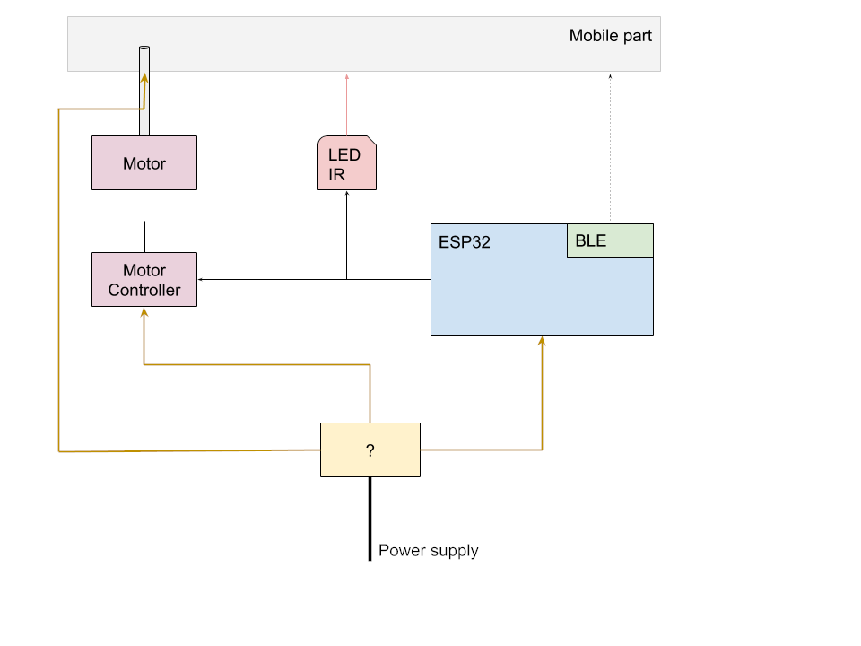
We’ve also been thinking about the fixed part of the project. We needed a way to control the motor and the IR LED used to synchronize the system. We tried to think about the usage flow, and finally came up with this :
- Push a button to turn the power on. This should power two BLE modules, one fixed and one mobile.
- When selecting or streaming a file through the WiFi interface, the mobile BLE module would communicate with the fixed part to start IR emission and motor rotation.
- When paused or stopped, the same process would happen to stop the motor.
It means that we’re going to have to design a (much simpler) circuit in the fixed part to control the motor and LED.
![]()
Choosing components
We’ve also started to choose components. In fact this is highly correlated to the architecture since we need to be aware of what’s existing to design the system.
Wifi
In particular, I’ve been searching for a WiFi module. After some research, I found the ESP8266 and its ESP32 family successors. These are particularly know, and adpated for our usage, because:
- The processor is dual-core, one core being dedicated to the IP stack, and the other being available for the user
- The processing power is sufficient for most usage. We are not going to do much work apart from forwarding data to the FPGA.
- It has 500 Ko of SDRAM and up to 16 Mo of external flash memory. This is clearly enough for our program and data.
- It is SPI and SDIO capable.
- It is cheap.
- It supports WiFi with an UDP throughput of 30 Mo/s
- It supports BLE
- It has a huge fan community, lots of tutorials and programming guides.
For all these reasons, we are going to use two ESP32 module. One will be used in the mobile part to handle the WiFi interface. It will also communicate through BLE with the second module on the fixed part. This is the module that will drive both the IR LED and the motor.
Moreover, the ESP32 is supported by, and mostly used with FreeRTOS. This is a sufficient reason for choosing FreeRTOS as our main OS.
Driver
I’ve been digging into TI website to compare their LED panel drivers. I noticed that two of their drivers are suited for “large high frequency multiplexed panels”. Furthermore, TI even wrote a document aimed at explaining the whole process of using those two drivers to build a panel. Since this is pretty much what we’re doing, it looked like a good idea to use those.
Ambroise checked the differences with other drivers that were available and noticed that, although the bandwidth is lower, they provide lower rising/fall time and most importantly have buffers to store the whole frame.
As a result, we are going to use the TI TLC59582.
-
Project design
06/13/2021 at 17:56 • 0 commentsIn this first post we would like to present the architecture of our project. It includes the choice of the type of components we will need, the way they are connected to each other and our estimations concerning their number.
Dimensioning
We will dimension our components to be able to handle a maximum specification, which we will very probably scale back according to the different bottlenecks we stumble upon during the duration of the project. Keeping last year’s project in mind, we are aiming at a maximum number of LEDs of about 2000, a rotation speed of 50 turns per second and a refreshing speed of each LED of 360 times per rotation. Knowing that and if we take 8 bits per color and 8 bits for brightness, we calculate a maximum bandwidth of about 150MB/s. In practice, we aim at an array of 40 by 30 LEDs in order to have a standard 4:3 display, given that we place the LEDs with the same pixel pitch in height and width.
We will control the LEDs by rectangular blocks. The size of each block is limited by both the number of PINs and the bandwidth of the LED driver we choose. We plan to choose a LED driver with at least the same characteristics as last year’s project: the ability to drive 16 LEDs at the same time with an input bandwidth of 33MHz.
![]()
Typical Application Circuit from TLC5957’s datasheet We estimate the Wifi throughput to be limited at 150Mb/s, which implies that we will need to implement a compression algorithm in our future file structure.
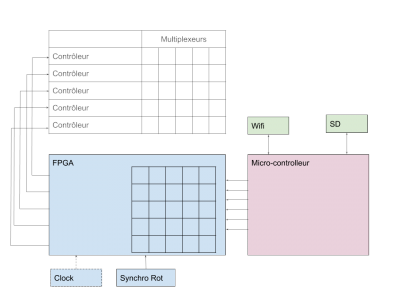
Elements choice
We will need:
- a Wifi module in order to stream data to the display
- an SD card reader
- a microcontroller unit in order to communicate with the Wifi and SD cartd reader modules
- an FPGA used to buffer the frames and driver the LED drivers
- a synchronization module in the form of an infra red sensor
- an OS to handle the modules
- voltage converters depending on the choice of components in order to supply accurate voltage to each one
![]()
For next time
We will choose the actual reference for each component.