-
New Boat, New Autopilot - using an old laptop mainboard!
08/09/2023 at 13:26 • 0 commentsFor quite some time I have been thinking about the possibility to using a laptop to run all the heavy OpenPlotter and OpenCPN stuff instead of using a Raspberry Pi. The performance of the RPi is... well it's usable but it's not a pleasant user experience. OpenCPN runs too slow and for anything else than what it's already doing (which, to be fair is a lot with GPS, AIS, Compass, Chart Plotting, Navigation, ...) it really is too slow.
I had an old Toshiba mainboard from my wife's old laptop flying around. It really fairly old but when I installed OpenCPN under the latest Ubuntu LTS for a test, I was surprised how well it handled the chart rendering.
I researched what is the main concern running a laptop for autopilot instead of the RPi and the only thing that constantly popped up was the compass sensor that PyPilot requires to do autopilot work. Fine, I thought, what are the options. Turns out, it's VGA.
What's VGA? It's an antiquated monitor port that no one uses anymore but it does break out an I2C port to read an eeprom inside the monitor describing what resolutions and frequencies it supports. It's wired straight from the CPU/IO buffer to the monitor. So can we use it for sniffing using the i2c-tools under ubuntu?
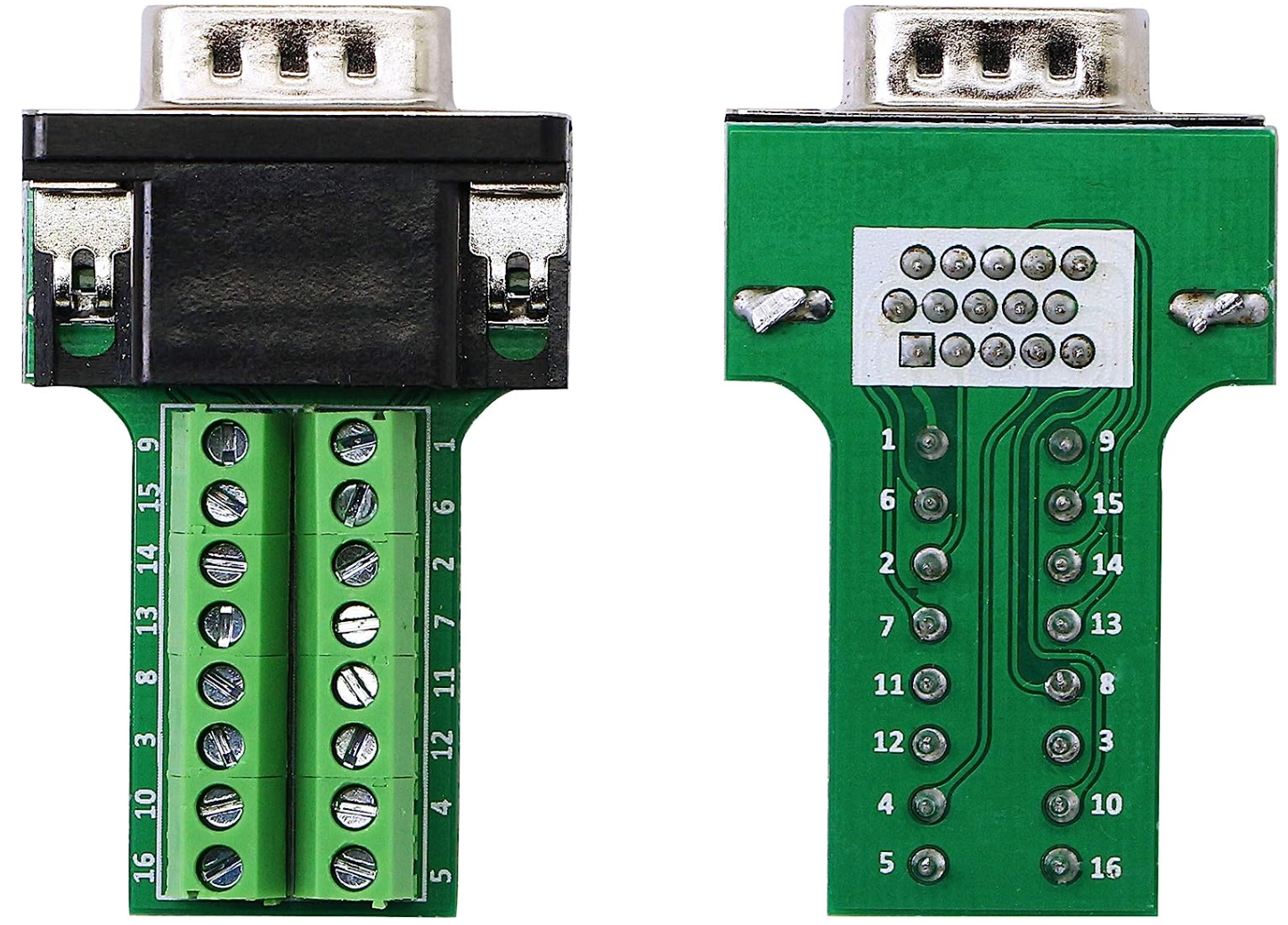
I got me one of these VGA breakout boards from Amazon:
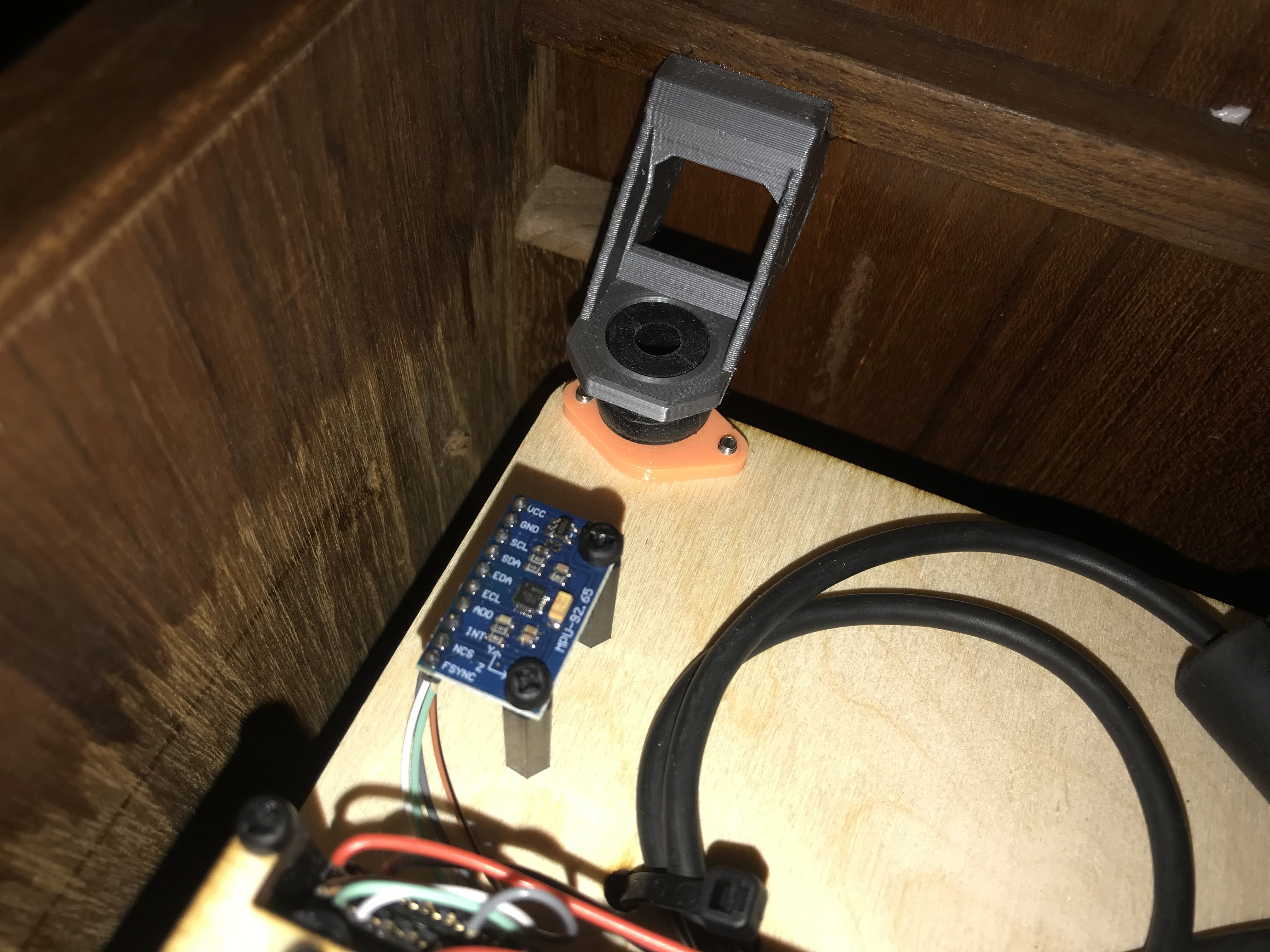
Hooked it up as follows to my IMU MPU9250:
- Pin 5 - GND
- Pin 9 - +5V
- Pin 12 - SDA
- Pin 15 - SCL
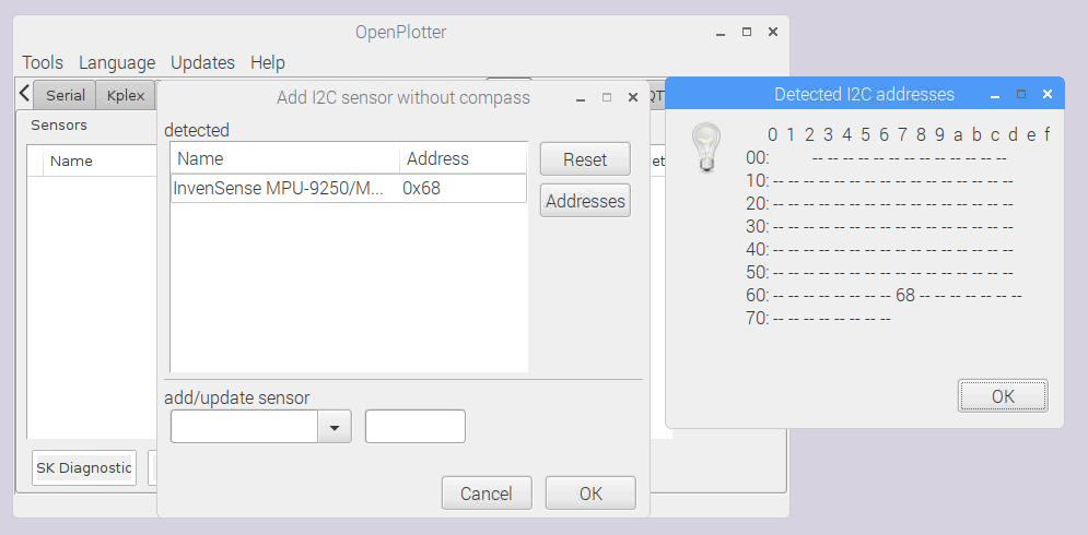
Then I ran the i2cdetect command to sniff what's connected to the port and voila!
chartplotter@chartplotter-Satellite-U505:~$ sudo i2cdetect -y 1
    0  1  2  3  4  5  6  7  8  9  a  b  c  d  e  f
00:                        -- -- -- -- -- -- -- --
10: -- -- -- -- -- -- -- -- -- -- -- -- -- -- -- --
20: -- -- -- -- -- -- -- -- -- -- -- -- -- -- -- --
30: -- -- -- -- -- -- -- -- -- -- -- -- -- -- -- --
40: -- -- -- -- -- -- -- -- -- -- -- -- -- -- -- --
50: -- -- -- -- -- -- -- -- -- -- -- -- -- -- -- --
60: -- -- -- -- -- -- -- -- 68 -- -- -- -- -- -- --
70: -- -- -- -- -- -- 76 --

chartplotter@chartplotter-Satellite-U505:~$ sudo i2cdump -y 1 0x68
No size specified (using byte-data access)
    0  1  2  3  4  5  6  7  8  9  a  b  c  d  e  f    0123456789abcdef
00: c2 d2 e3 f0 ab de 29 c0 08 29 04 03 00 69 61 70    ??????)??)??.iap
10: c7 ba ec 00 00 00 00 00 00 00 00 00 00 00 00 00    ???.............
20: 00 00 00 00 00 00 00 00 00 00 00 00 00 00 00 00    ................
30: 00 00 00 00 00 00 00 00 00 00 05 3d c0 f2 04 0b    ..........?=????
40: a8 0e b0 fd b0 00 52 ff e2 00 00 00 00 00 00 00    ?????.R.?.......
50: 00 00 00 00 00 00 00 00 00 00 00 00 00 00 00 00    ................
60: 00 00 01 00 00 00 00 00 00 00 00 01 00 00 00 ea    ..?........?...?
70: 00 00 00 00 00 75 00 e1 b6 00 ea 10 00 27 da 00    .....u.??.??.'?.
80: c2 d2 e3 f0 ab de 29 c0 08 29 04 03 00 69 61 70    ??????)??)??.iap
90: c7 ba ec 00 00 00 00 00 00 00 00 00 00 00 00 00    ???.............
a0: 00 00 00 00 00 00 00 00 00 00 00 00 00 00 00 00    ................
b0: 00 00 00 00 00 00 00 00 00 00 01 3d b0 f3 48 0b    ..........?=??H?
c0: 3c 0e 90 fd d0 00 83 ff dc 00 00 00 00 00 00 00    <????.?.?.......
d0: 00 00 00 00 00 00 00 00 00 00 00 00 00 00 00 00    ................
e0: 00 00 00 00 00 00 00 00 00 00 00 01 00 00 03 b4    ...........?..??
f0: 00 00 00 00 00 75 00 e1 b6 00 ea 10 00 27 da 00    .....u.??.??.'?.
Shockingly, this just worked and the IMU popped up!
Disclaimer: The dump here is not actually from that specific IMU but from another one but it's just an example that it works!
With the IMU connected, I installed Openplotter as usual. Download the Settings app and from there, install everything. Or at least so I thought. A couple caveats: PyPilot can only be installed on Raspberry Pi using the Settings app. Given the above appears to be no issue at all, this doesn't seem to make any sense anymore and should probably be changed if there are no other good reasons.
Instead, one has to hop over to the git repository and install PyPilot manually.
Right after, one can go ahead and install it as a service on the system so that it start automatically when the system starts. Since we didn't install it using the Settings app, it won't start otherwise as OpenPlotter doesn't know it exists. I followed this documentation to get the service installed but it would not start.
We have to go to the service script it installs and change a few things:
- By default, PyPilot assumes it runs on a Pi. So the user name the services uses is pi. We need to change this to whatever username we have chosen for the system. In my case simply chartplotter. With that change, PyPilot started but it grabbed all my serial ports and SignalK (which is the data distribution software OpenPlotter uses for communication of all the sensors on your boat) couldn't access any of them anymore.
- So I added a delay of 30 seconds after the system has booted to start the service. This service will also take care of auto-restarting PyPilot, should it ever crash.
- Additionally, I highly recommend creating two files within the ~/.pypilot/ folder. You want to add the ports you don't want PyPilot to see/probe to the blacklist and only add the ones you want it to use to the serial_ports file. Otherwise, whenever anything happens to SignalK (say a crash and restart) PyPilot will just grab the ports and not release them. I only wanted PyPilot to communicate with my motor controller and not the GPS sensor or anything else serial.
- blacklist_serial_ports
- serial_ports
My services file looks like this:
TODO: Add file contents
I'm not sure the last step is important, but I read somewhere that to run services that require a sudo/root password to do stuff as a user (for instance to access I2C ports, one needs to allow the user to run sudo commands without requiring a password. This is a highly questionable choice and depending on what else you are using the system for poses extreme security risks. So it it at your own discretion should PyPilot not start as intended.
Getting AIS to work reliably WITH an IMU connected to the I2C port:
Now that everything worked - including AIS, I restarted and... AIS stopped working. The reason turned out to be that once an RTL-SDR dongle is plugged in, the I2C multiplexer on the RTL-SDR that is not used by anything is registered by the system and a module is loaded for it. Once that happens, the I2C port 1 used for the IMU. In order to fix this, I found that blacklisting lots of RTL-SDR modules during boot is a usable solution. Luckily, someone already figured out what modules to blacklist so I was able to just follow this short guide:
-
Running a Test
12/16/2019 at 00:41 • 1 commentNothing is more exciting than the first time a system comes to life and can be tested. The last two weekends, I was fortunate to have great weather to be able to run a few tests! Last week, I got course keeping to work, this week I got waypoint following to work!
The first time, things came to life I had the suspicion that my rudder command might go into the wrong direction. And sure enough, even though the the buttons for "go a little port" or "go a little starboard" were functioning at the dock, the moment I started using the automatic course keeper, the boat always steered in the wrong direction! Not sure why but my solution was simply to swap the direction on the H-bridge to get around this. Now, the "steer more starboard" doesn't work anymore but course keeping and waypoint driving works. So I don't care much. It looks like a bug in PyPilot to me because no one is using those buttons anyways. Usually everyone either steers manual or sets a course. So that's fine.
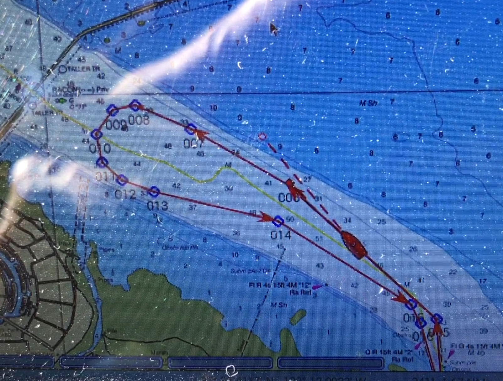
Today, I got the waypoint driving tested.
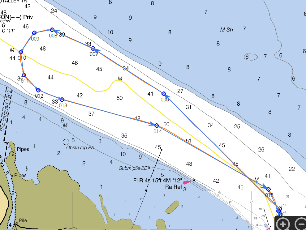
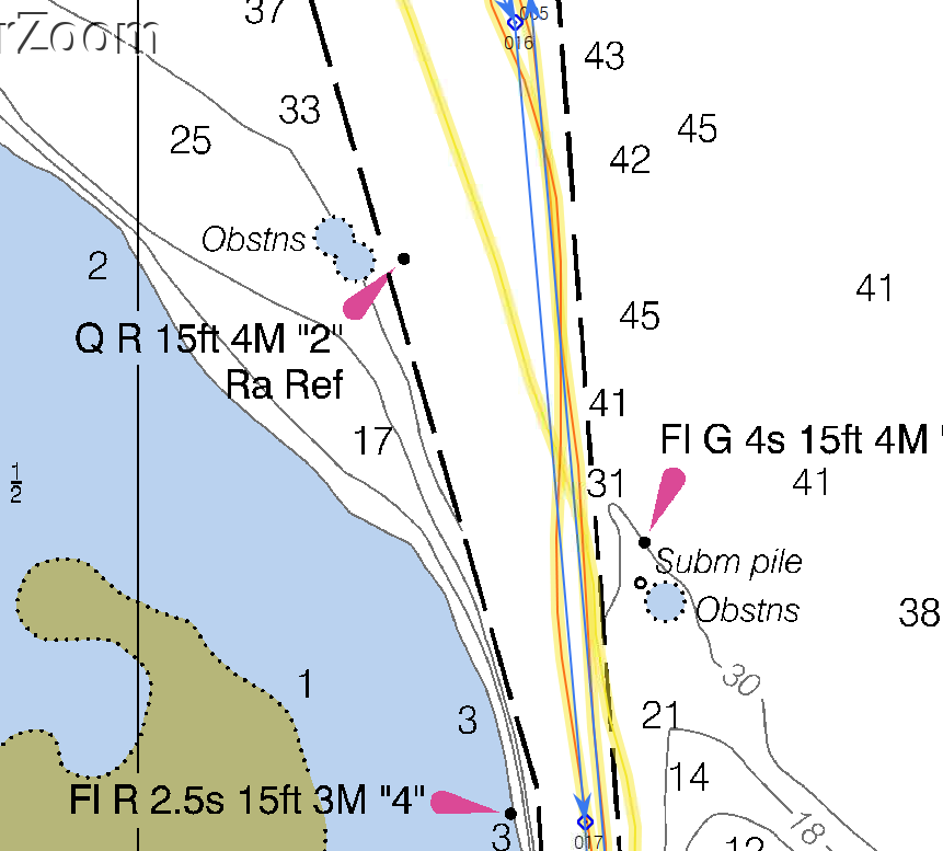
Above was the active route that I was driving at the time, below is a screen capture of the same, after the fact.
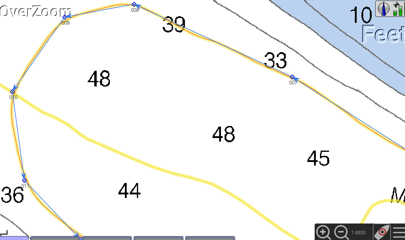
If we zoom in, you can see the boat is not following the course super accurately but it's definitely good enough to be on watch but not actively participating in the course correction of the boat:
It is really impressive how a 36 ton boat just drives from waypoint to waypoint without breaking a sweat or caring. The controller just does the job. Care must be taken, though, where to place those waypoints! DO NOT place the waypoints too close to land marks! Like buoys or similar. Since external factors will push the boat away from its desired path you will hit things if you're not careful. People have lost boats because of this! It's no joke! Watch the boat like a hawk and take over immediately the moment the slightest doubt comes up!
Here you can nicely see how my boat is still oscillating slightly and not actually going in a straight line:
I'm sure I can optimize this a little bit but I don't care much about this inconsistency right now.
-
Implementing the Motor Controller
12/15/2019 at 23:58 • 2 commentsWhen things are not so easy...
I ran into a trouble when I tried to understand what was required to get the motor controller to PyPilot to work. I thought, it should be easy to just hook up an Arduino to an H-bridge that you can easily obtain from Amazon or Ebay and have the system communicate happily. However, I ran into documentation issues right from the start, couldn't find a part-list, couldn't find schematics and so on and so forth.
Turns out code and schematics are available but it took me the better part of a week to understand what's going on in the arduino code and I didn't like the schematics.
Please do not get me wrong: What the original author, Sean, put together is amazing overall! But the motor controller, which was specifically designed to run a bare metal H-bridge at 16khz by doing bit banging on the Arduino, left much to be desired in terms of ease of use and serviceability. So I rewrote major parts of it and restructured others and I hope, this version is a bit easier to understand and to get to work.
Yes, I am aware of the "not invented here" principle but I also strongly believe in opensource and feel like I did contribute to the overall scheme of things by putting this together and publishing what I have learned in the process.
Let's talk about parts:
- IBT_2 fully integrated and protected H-Bridge I found to be very powerful and reliable so far
- Arduino Nano Clone
- 160x128 pixel TFT display
- Two NTC 100k thermocouples you would just order for your 3D printer
- A 5Kohm potentiometer as a rudder sensor
- Couple wired resistors to make a single sided board possible
- Some pin headers
- Several 3d printed parts
![]()
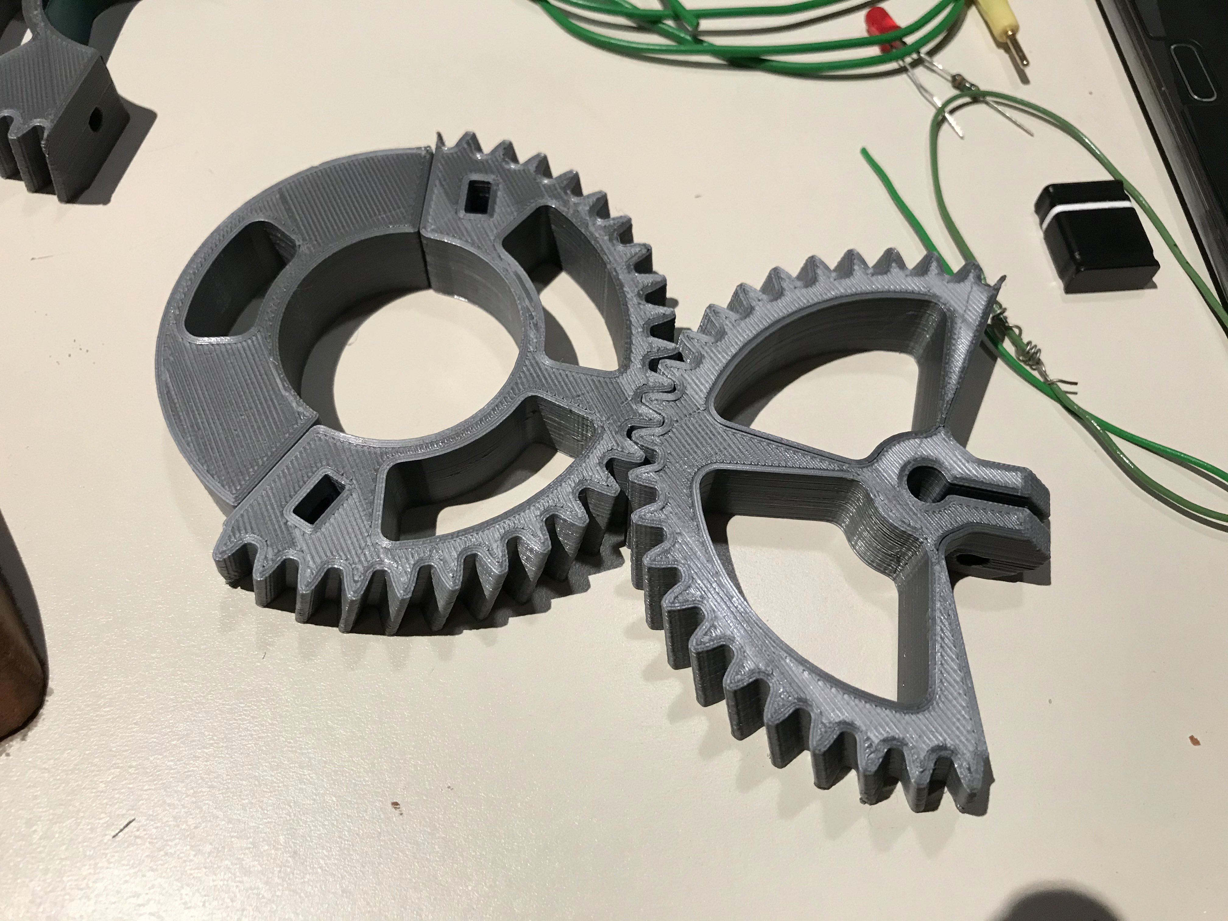
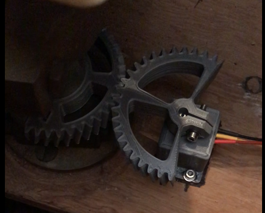
The parts above are for my rudder sensor. The gear on the left clamps around one of my two rudders, the gear on the right is bolted straight to my 5K poti.
This gives me a really nice rudder position feedback which is used for telemetry and to let PyPilot know that it shouldn't push into the MAX and MIN any longer using the rudder actuator.
![]()
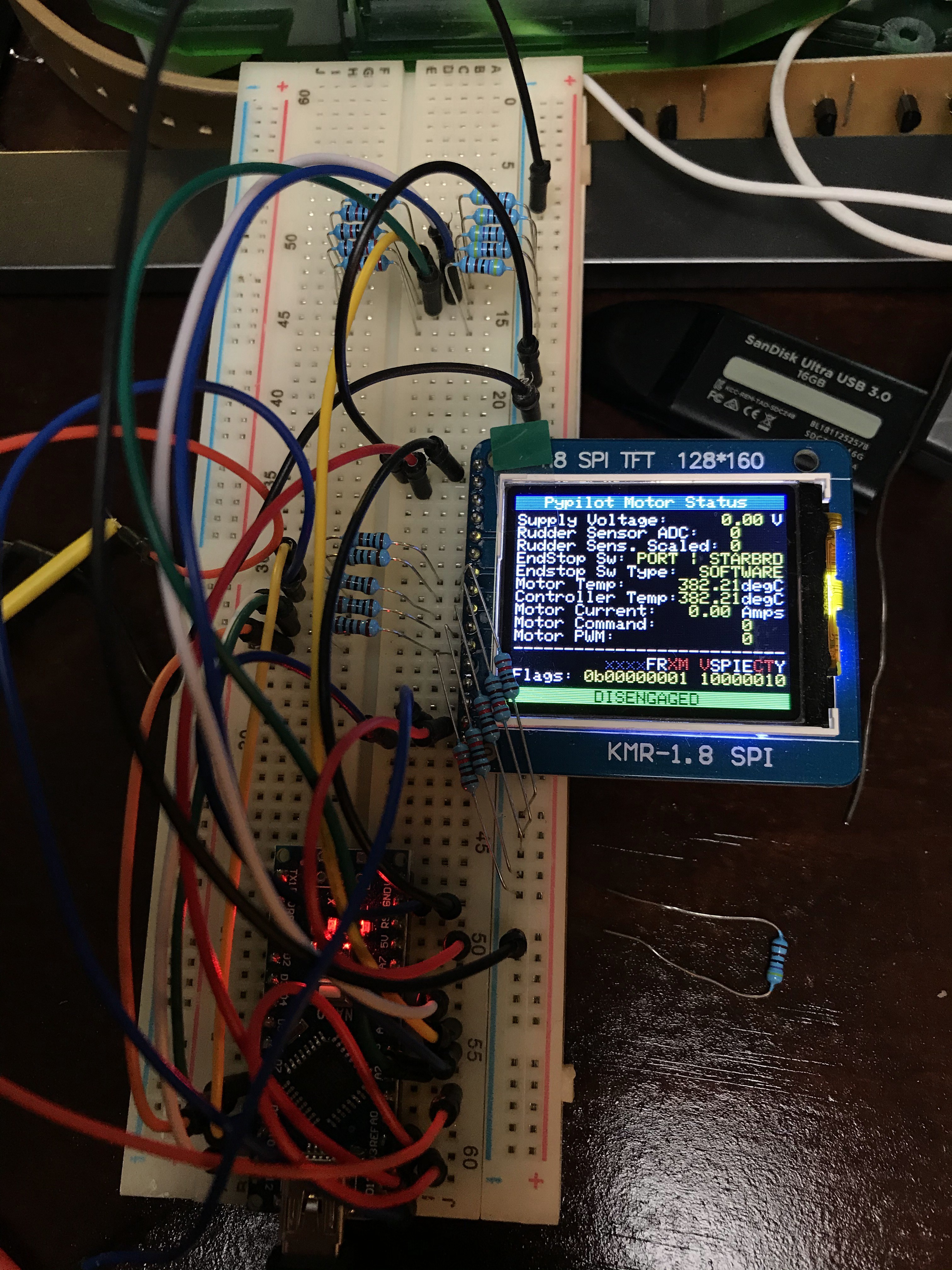
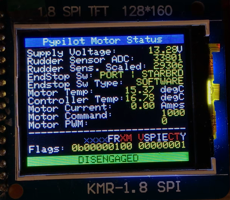
As with many other projects, I usually start with a breadboard. I like having a display to be able to quickly debug the system. Like in this case, the uart port is already in use to communicate with PyPilot and cannot easily be repurposed for debugging. So I added the super high performance TFT library ST7735 to my sketch and added the display functionality.
![]()
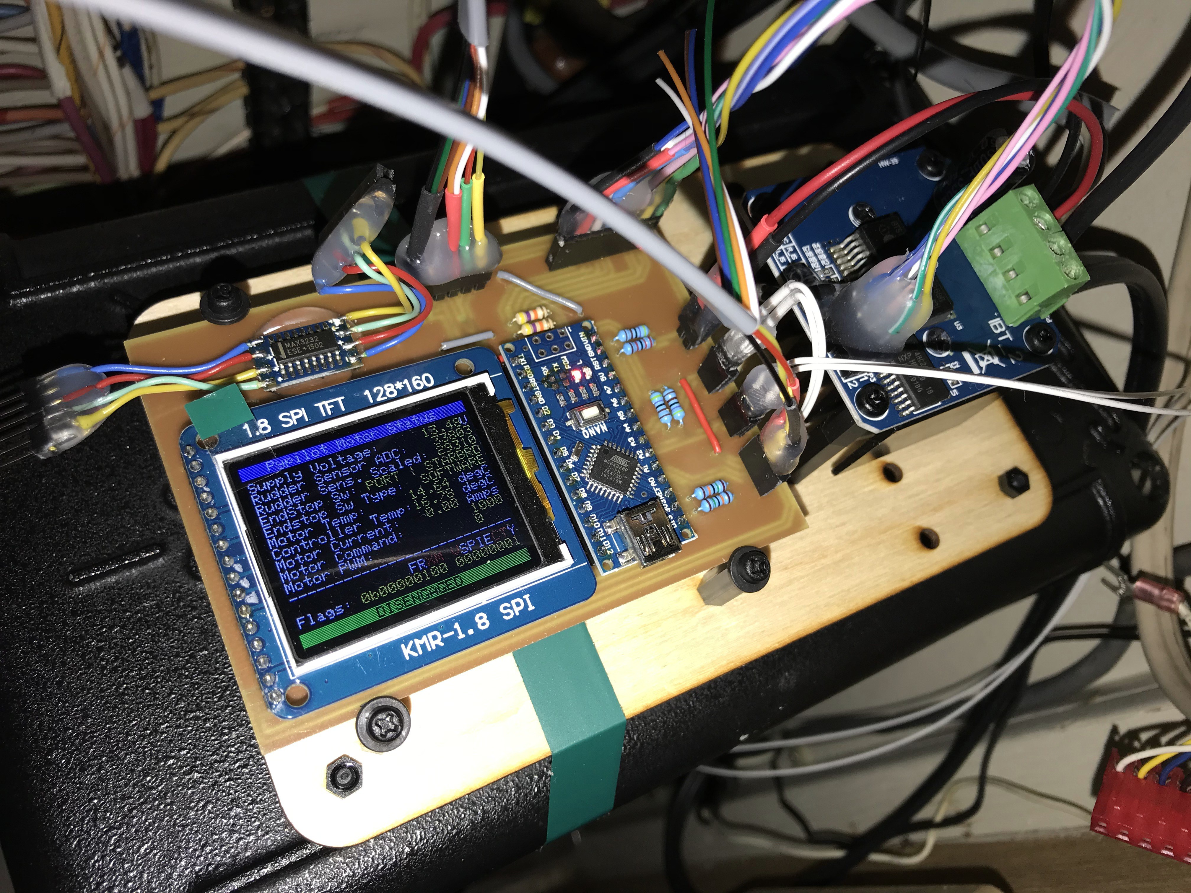
Now I needed to put everything into one device instead of flying wires and bread boards since I wanted a more permanent installation.
I used KICad to create schematics for the board and created a layout for a single sided, easy to make at home PCB which I then milled out on me $200 PCB mill that I still love to death:
![]()
![]()
The code for this motor controller branch can be found on my github page.
The motor controller code is located under Arduino/Motor/Motor.ino. Please let me know if you have any issues with the code. Please keep in mind that you will need the display library, unless you deactivate the display in the config.h header file.
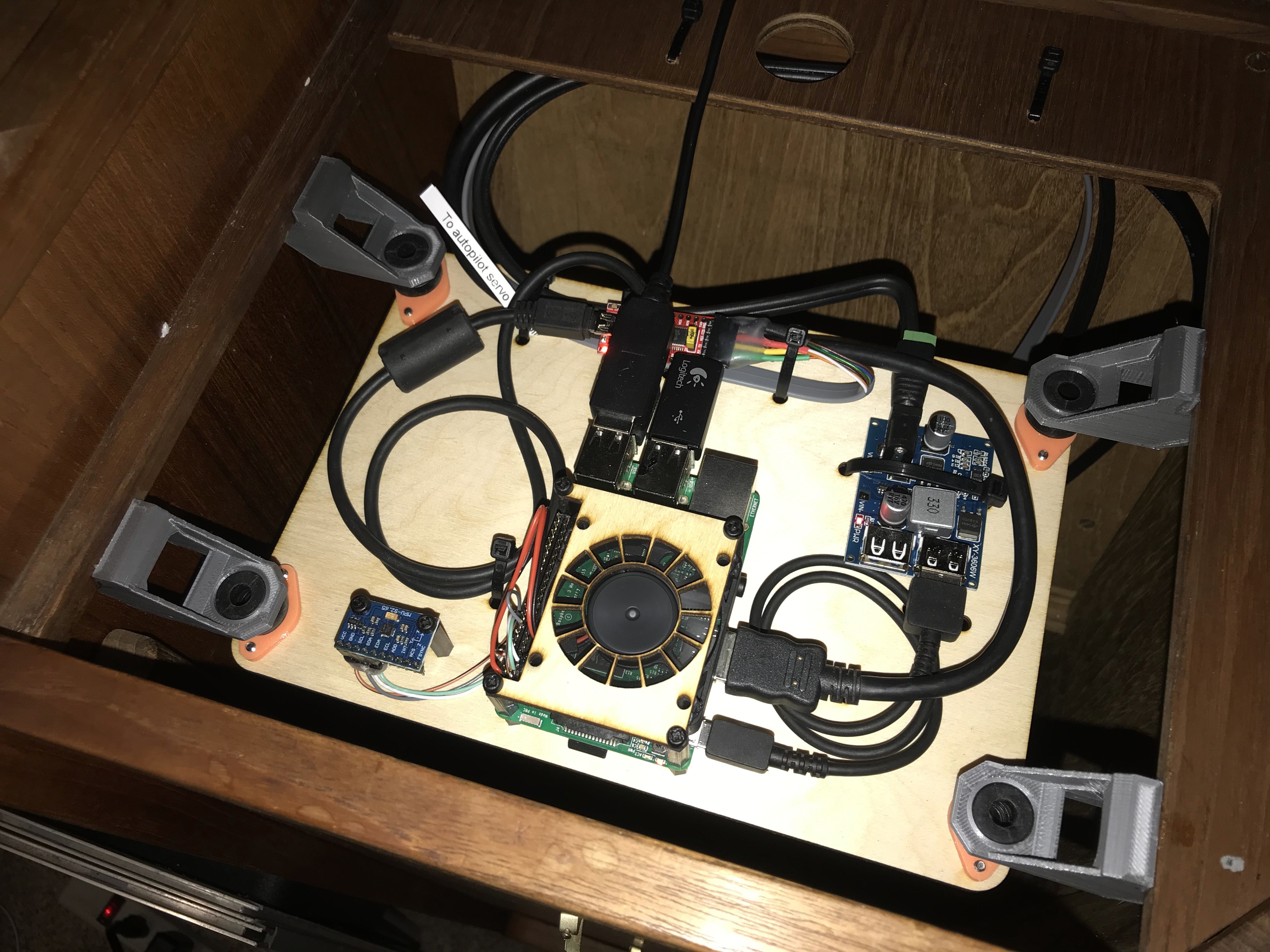
On the Raspberry Pi 3 side, the implementation looks as follows. I integrated it into one of two helms using rubber dampeners that one would usually use for vibration isolation on camera gimbals and the like.
![]()
![]()
As a power supply, I used a 12V to 5.2V high speed charging circuit. This thing is definitely able to drive the PI3 under load with no issues without showing the dreaded low power warning.
-
Things come together
12/15/2019 at 23:01 • 0 commentsFor a couple of weeks, I was in between jobs. I quit my old job and signed up for a new one. The time in between was a bit of an unpaid vacation and I used my time to pay myself. I always wanted to install a full blown autopilot on my boat because my girlfriend and I are boating in a nice area and either myself or her are required to be at the helm at all times. Even when there is absolutely no one around. The boat simply doesn't steer itself.
That needed to change, so I spend a couple days researching my options, initially bought an ArduPilot Rover kit and wanted to use that. However, it became clear, that ArduPilot kinda sorta uses google maps or similar to create missions but I needed something marine, like a chart plotter.
After some further googleing, I found OpenPlotter! An open source platform, compatible with the Raspberry Pi 3 - of which I have a bunch sitting on the self collecting dust. On top of the ecosystem this project created, they have an OpenCPNintegration and that has an PyPilot integration!
All together, this is a complete chart plotting, autopilot solution with the ability to integrate various sensors and other systems like AIS! Quite impressive, really, and supported by a large community - with varying success, as I will explain in a bit.
Installing OpenPlotter could not be easier as there is a NOOBS image available that contains everything needed to get things running. Just flash it to a microSD card like you would to install any Raspberry Pi OS and fire it up. Just follow the very good documentation.
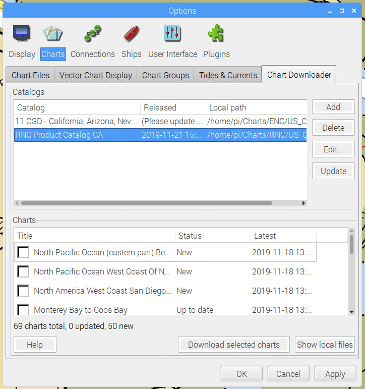
I then started OpenCPN and installed some charts. I'm not entirely sure which ones I installed but there are several.
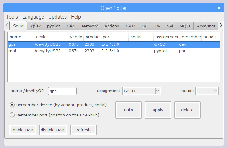
Once charts are installed and a GPS is plugged into the USB port, you need to configure it using the OpenPlotter application:
Please note, when you plug two of the same USB to Serial converters into the Raspberry Pi, you have to let the the system know to remember what port you plugged each one into. Otherwise, the system may wake up expecting the GPS to be where the PyPilot is connected.
I plugged each one in individually, configured it by giving it a name and an assignment and then hit apply. GPS will be detected automagically, PyPilot as well.
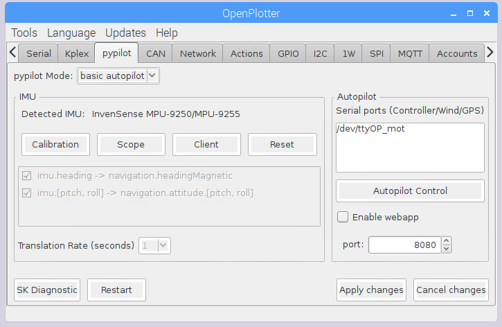
Next up is the IMU. I strongly recommend buying the suggested IMU:
I tried to get other ones to work but this one just works out of the box and need to further configuration. It's a whole $9 on Amazon so there is your big investment for this project!
It's a little funny that the IMU only shows up under PyPilot and not under I2C even though it is connected through I2C. However, if you go to I2C and then hit add, it will show it, once connected correctly, and it will also show the addresses:
There is no need to ADD the IMU to the I2C sensors. PyPilot will just take it once connected.
At this point, you have GPS and an IMU for the compass.
Now, we need to let OpenCPN know where to get all the sensor information. OpenPlotter uses an app/daemon called SignalK which is kinda like a hub apps can connect to to get access to all sensor data. This includes AIS, NMEA2k as well as NMEA0183 if all of that is actually connected to the Pi.
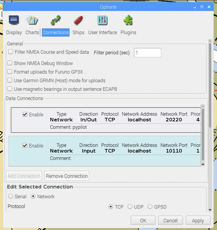
In OpenCPN, go into the settings and click Connections:
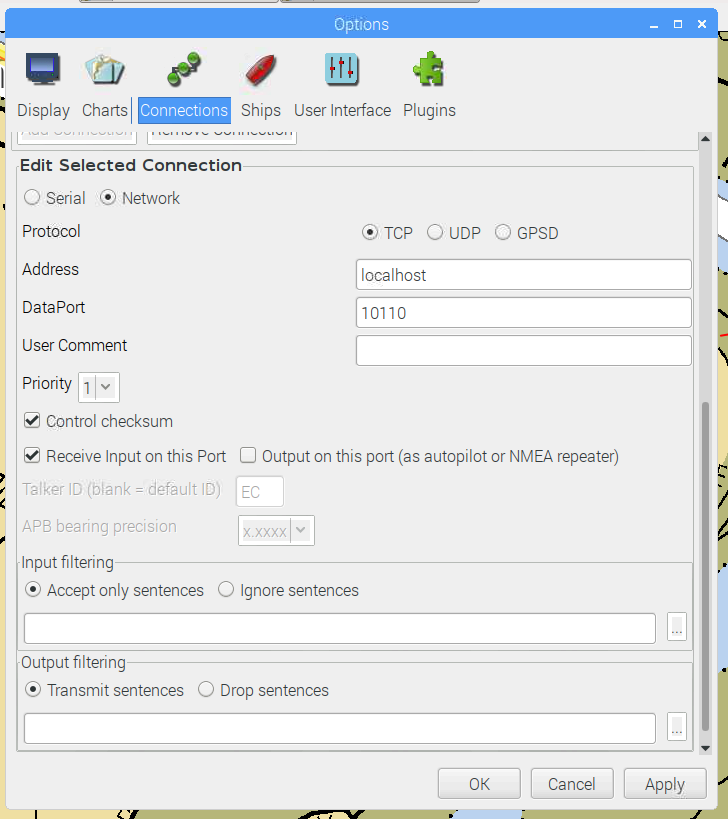
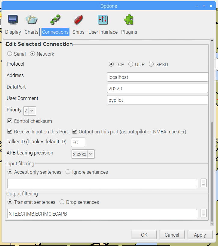
There are two things that you need to set up. The connection to port 10110 to gain access to the SignalK hub / multiplexer and the connection to PyPilot. In my case, everything runs on the same Raspberry Pi so localhost is the correct IP address.
Port 10110 supplies all the sensor data and needs to be configured as an input as we only want to receive information and 20220 is autopilot data (waypoints) going to PyPilot. Here, we should select the NMEA messages we want to send to PyPilot to reduce the amount of data that needs to be sent and processed:
That's kinda it! This is how I set my system up and so far it works like a charm.
What's really important is that you tune your PID controller. You probably only really need P and D and ignore the I-gain but they need to be tuned a little bit to not have the system freak out the first time you actually activate the autopilot / course keeping.
-
Implementing a Rudder Sensor
11/22/2019 at 00:50 • 0 commentsIn order to be able to safely control the servo pump for the steering system, I need a sensor to measure the rudder position.
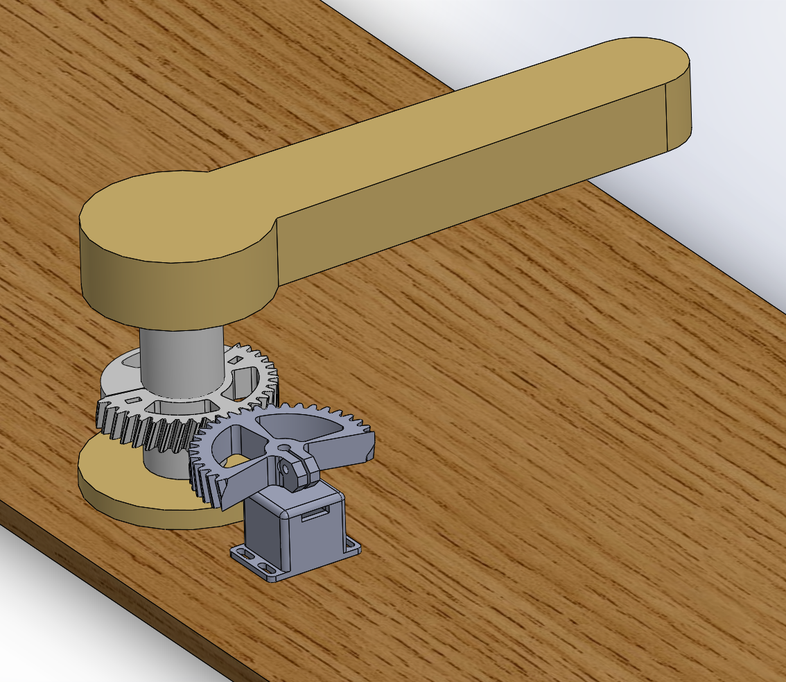
I modeled a simple representation of the steering system and them thought about how to add a sensor to the structure. I have seen multiple people adding potentiometers using some levers and joints but I concluded that this is too complex and non-linear.
So I selected and downloaded design files from my new favorite gear provider: KHKGears
I then modified those gears to my liking and through them onto my 3D printer. This is an amazingly simple way of getting compatible gears in almost all sizes and complexities.
The sensor is a simple 5KOhm potentiometer in a 3D printed bracket, bolted to a plywood board. If I want to, I can simply add another sensor 90degrees offset of the first one to get a differential, redundant sensor signal. This might be necessary to really be able to trust this in the long run.
Currently, these gears and brackets are printing. Unfortunately, my Chinese supplier for the potentiometer has not managed to send me the parts since FEBRUARY! So I just ordered new ones, shipped from the US.
OpenCPN Chart Plotter /w Autopilot and Waypoints
I am in the process of implementing an autopilot on my 42' Uniflite Aft Cabin Cruiser based on the original 1984 hydraulic steering system.
 Timo Birnschein