 Tom
Tom-
Hardware Overview
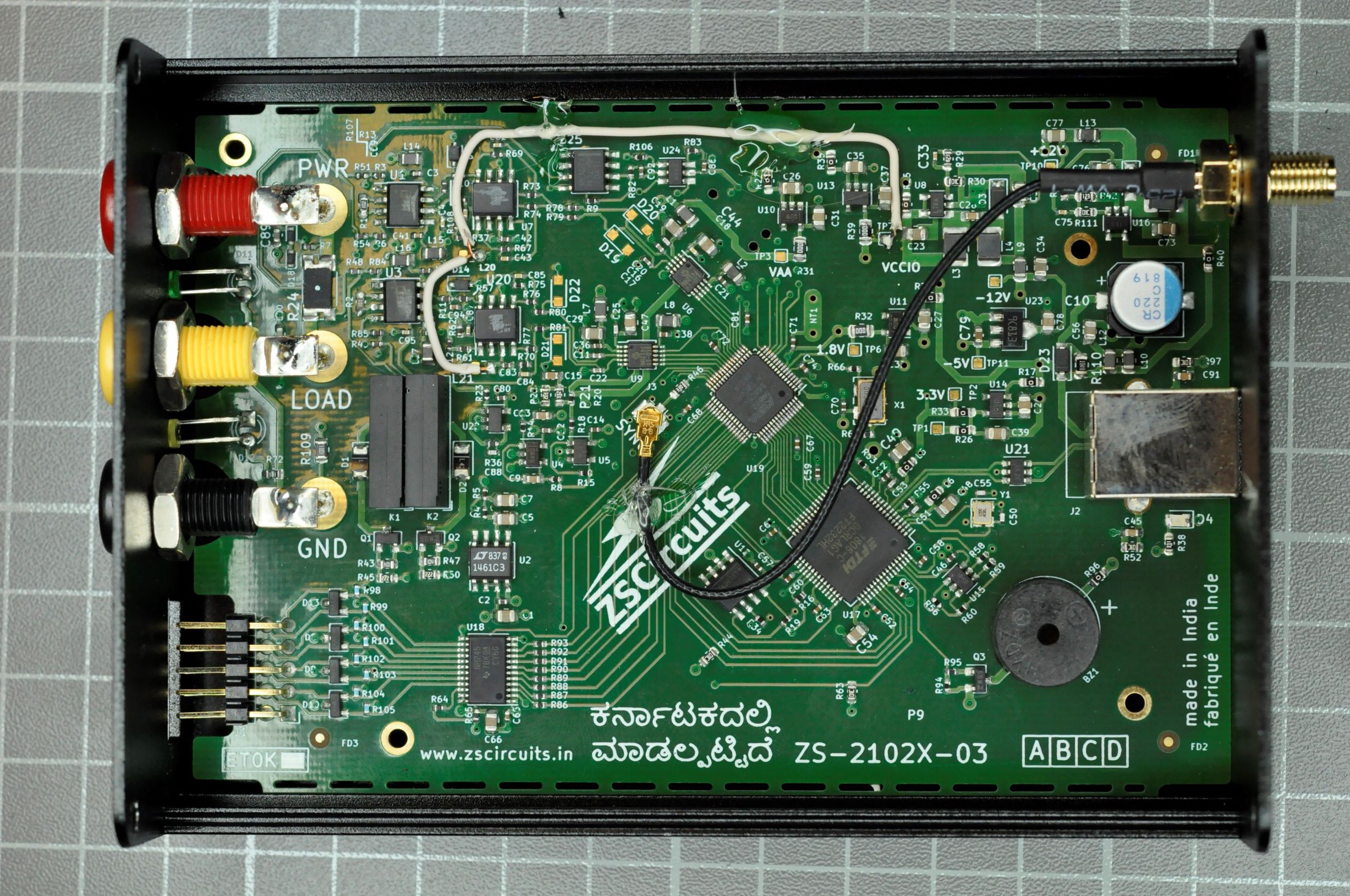
11/26/2019 at 17:40 • 2 commentsWhen opening the housing,
![]()
there are some eye-catchers:
- The part numbers of the instrumentation amplifiers and of the differential amplifiers are burnished away.
- The white wire which connects the negative supply of the differential amplifiers.
- There is no galvanic insulation between the USB port and the measurement circuit.
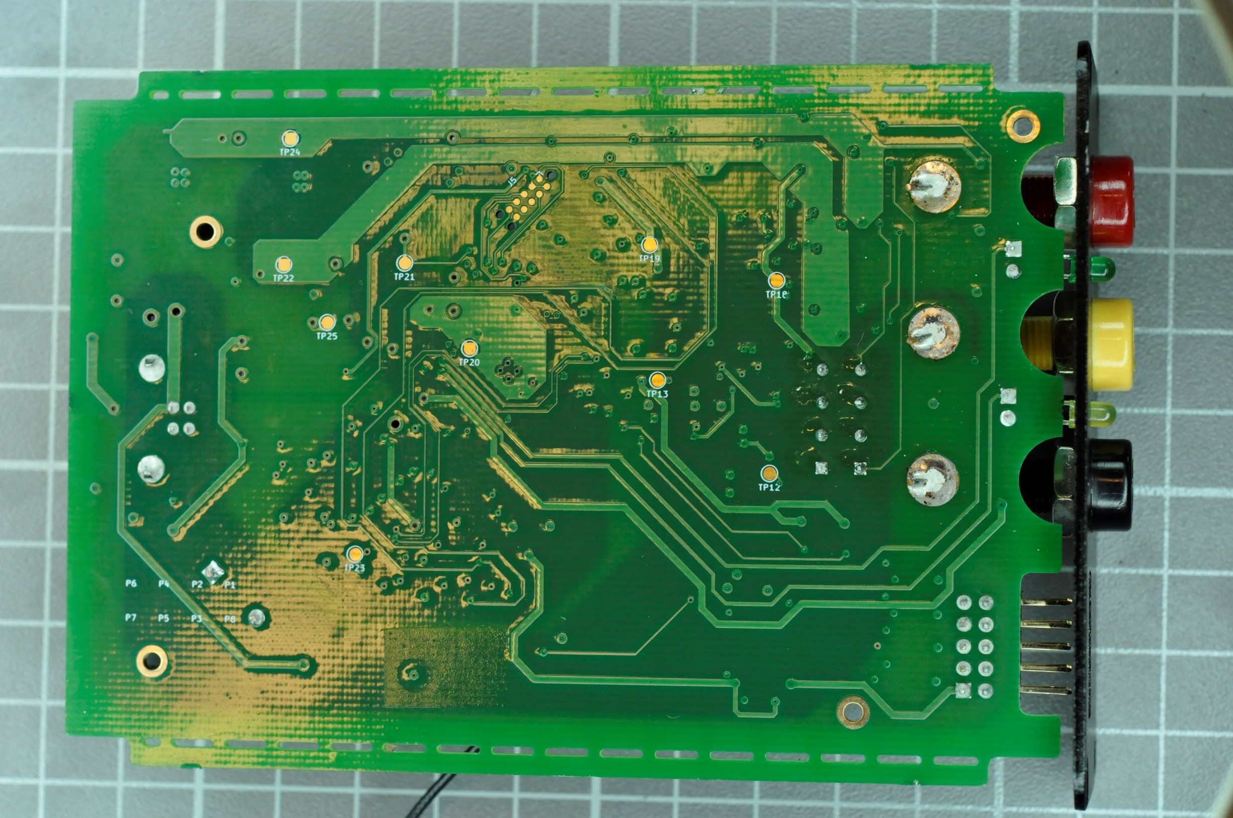
The PCB is assembled single sided, probably it is a 4 layer stack-up.
![]()
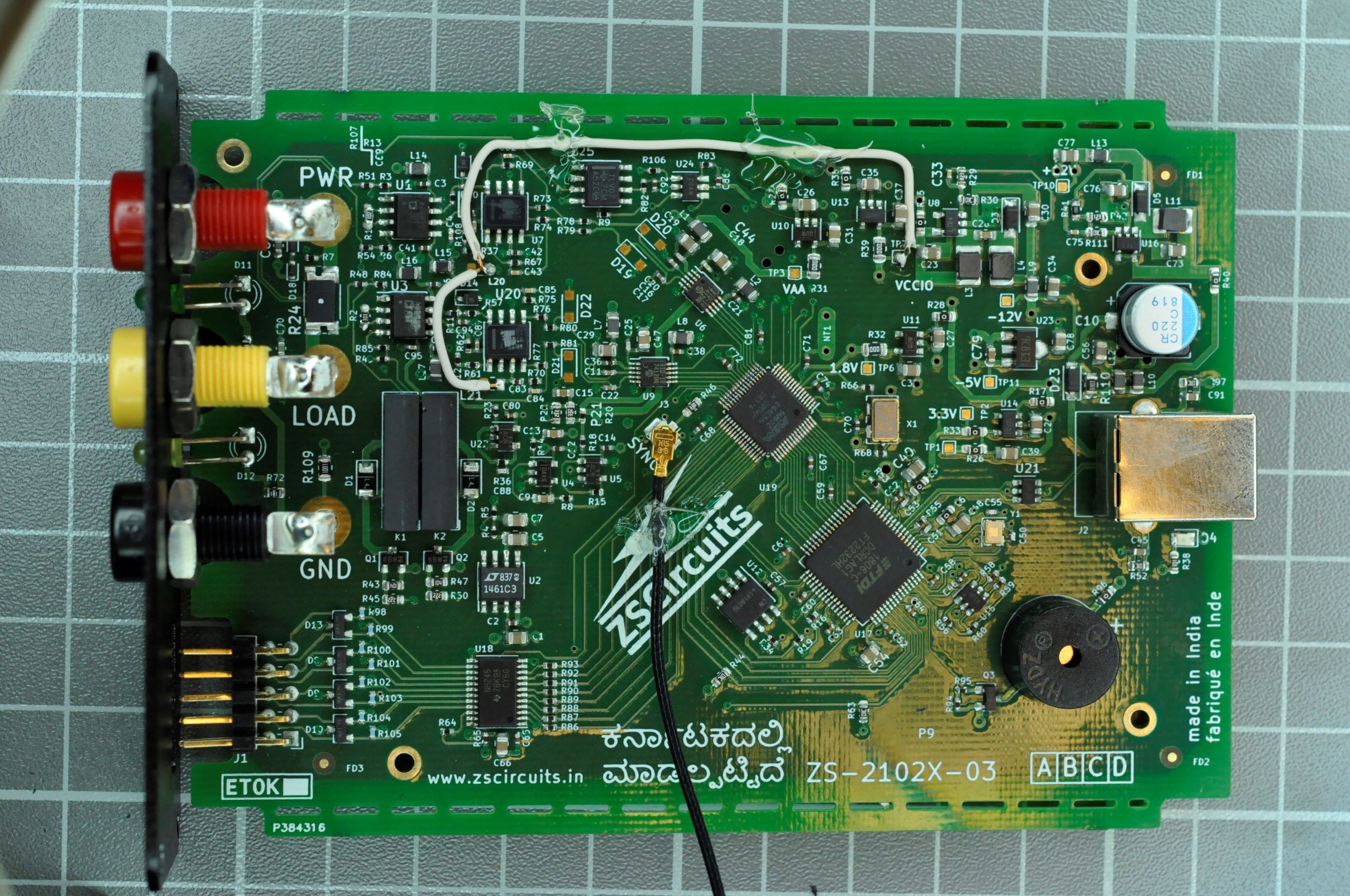
![]() Using a microscope i was able to read the part numbers of the burnished components. You find a list of the key components in the components list!
Using a microscope i was able to read the part numbers of the burnished components. You find a list of the key components in the components list!The clock output of the device is connected directly to the CPLD pin using a 33 ohm resistor.
From the hardware perspective this devices looks well designed with little discomforts:
- The 4mm banana connectors do have a very bad quality
- There is no galvanic insulation between the measurement circuit and USB
Teardown ZS-2102-A
As I actually had the chance to use and test this device, i couldn't resist to open it.
 Using a microscope i was able to read the part numbers of the burnished components. You find a list of the key components in the components list!