-
Mk III
04/10/2020 at 01:18 • 0 commentsUpdates
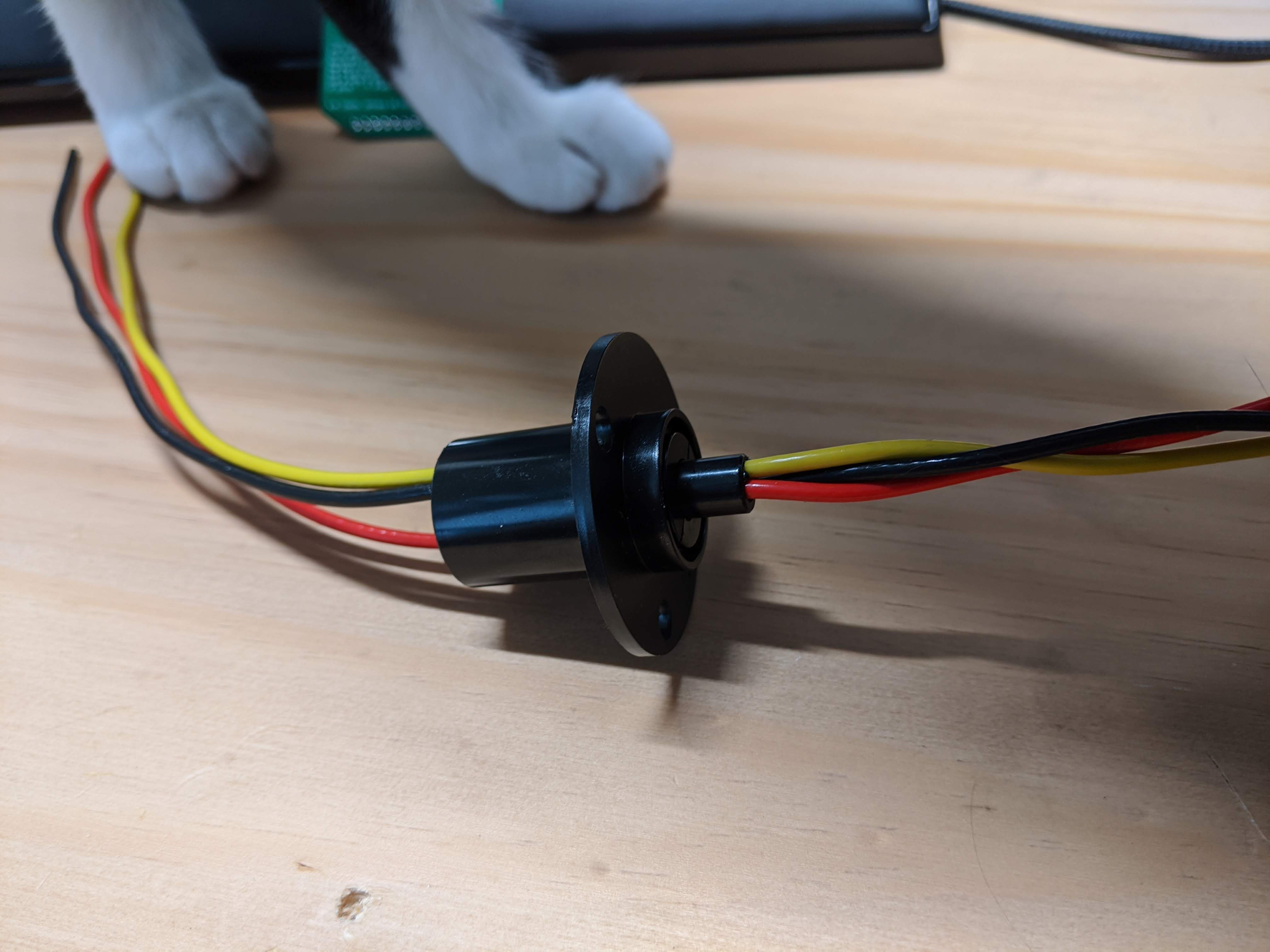
Quit with the custom-made slip ring business and bought a couple of <$10 three-wire ones from eBay.
![]()
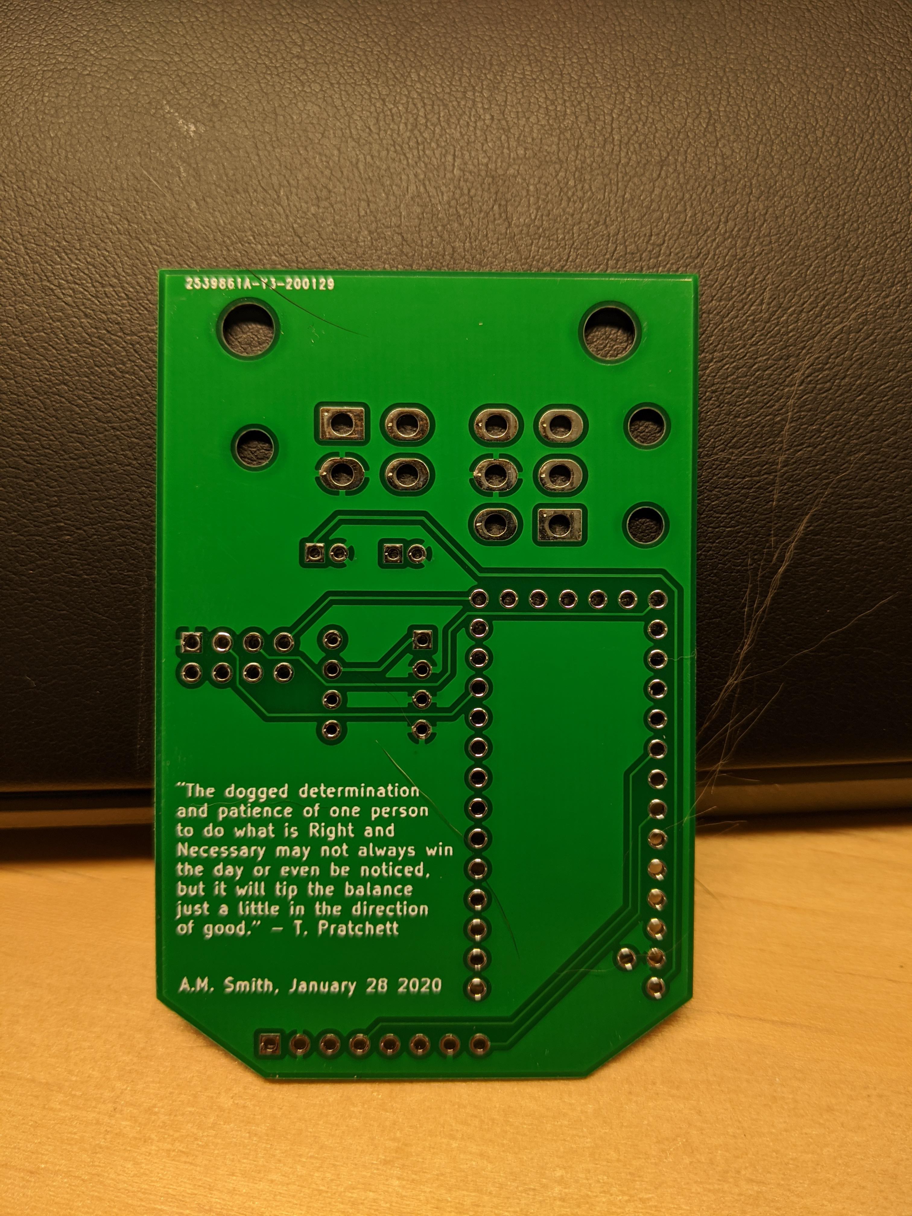
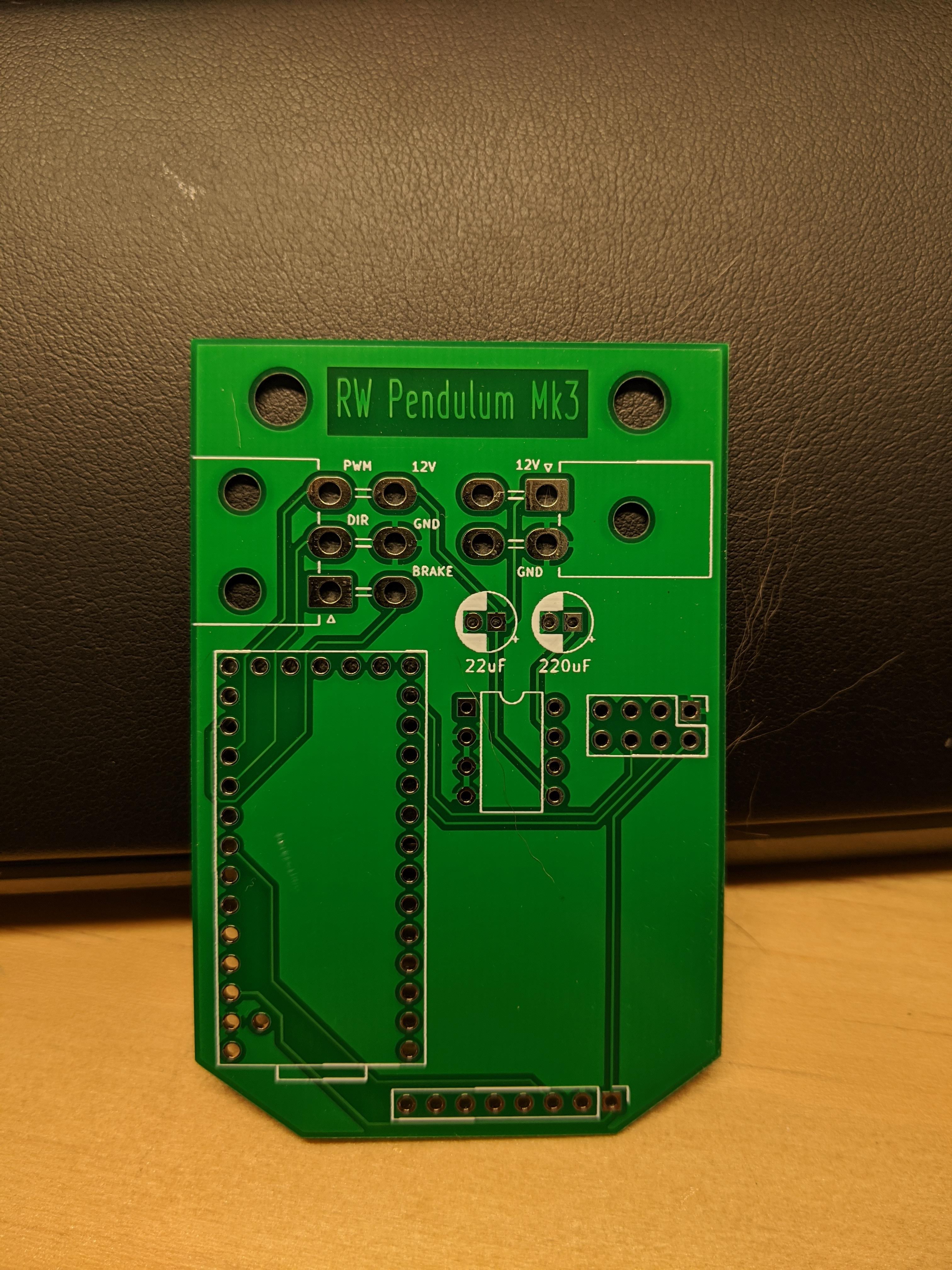
PCBs finally came in from jlcpcb after a long COVID-19 delay:
![]()
![]()
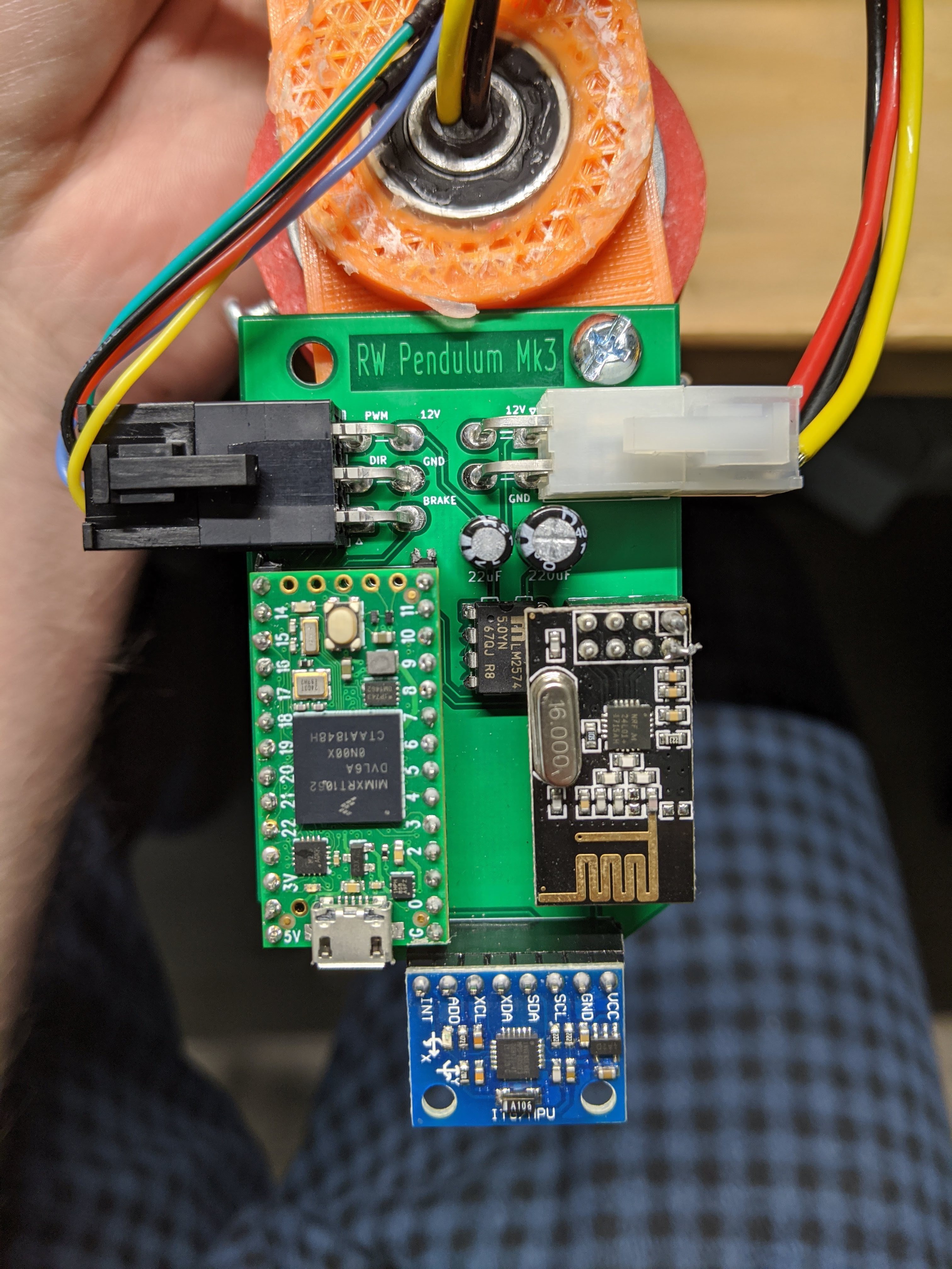
Soldered all together:
![]()
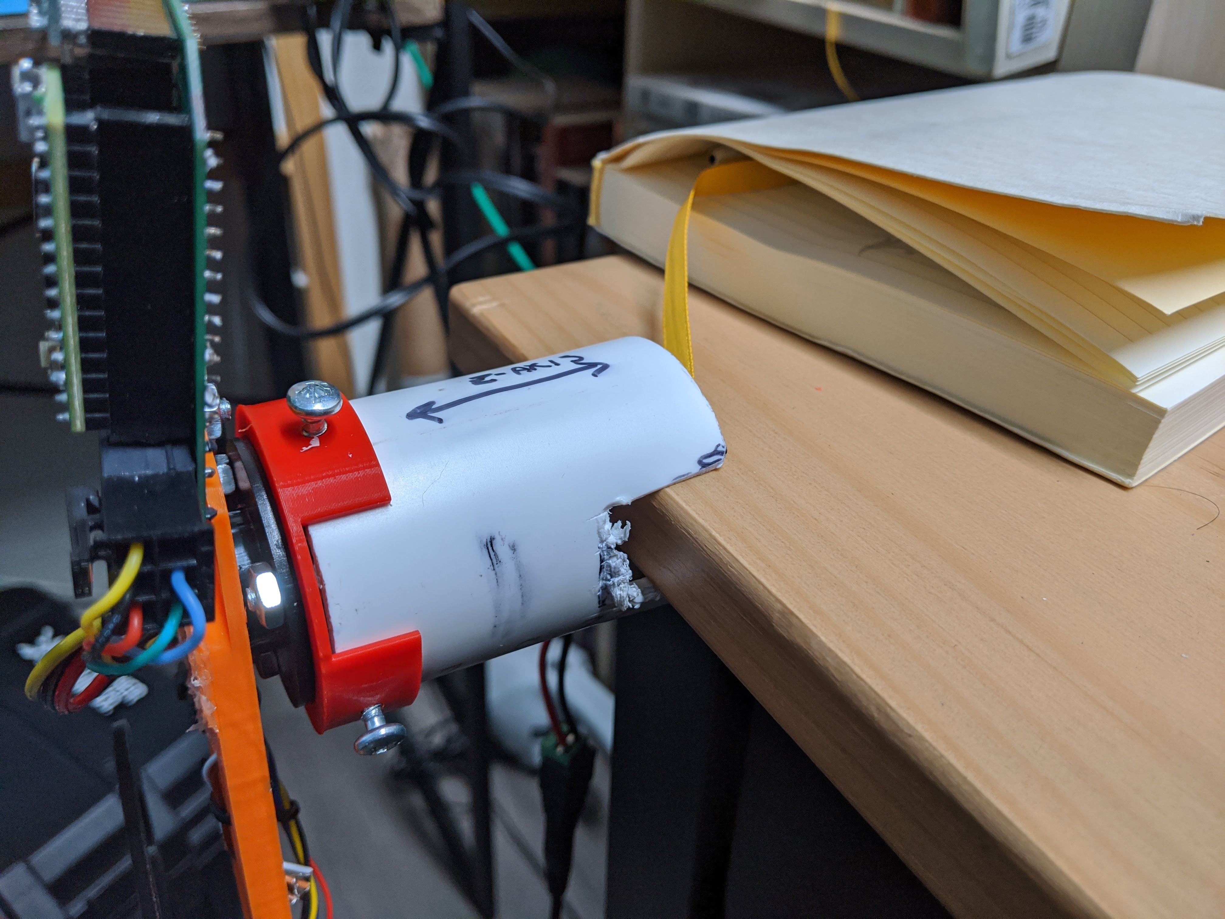
Designed a mount for a spare piece of PVC pipe. Really didn't want to put too much more effort into the mechanical design as this was supposed to be a control systems project.
![]()
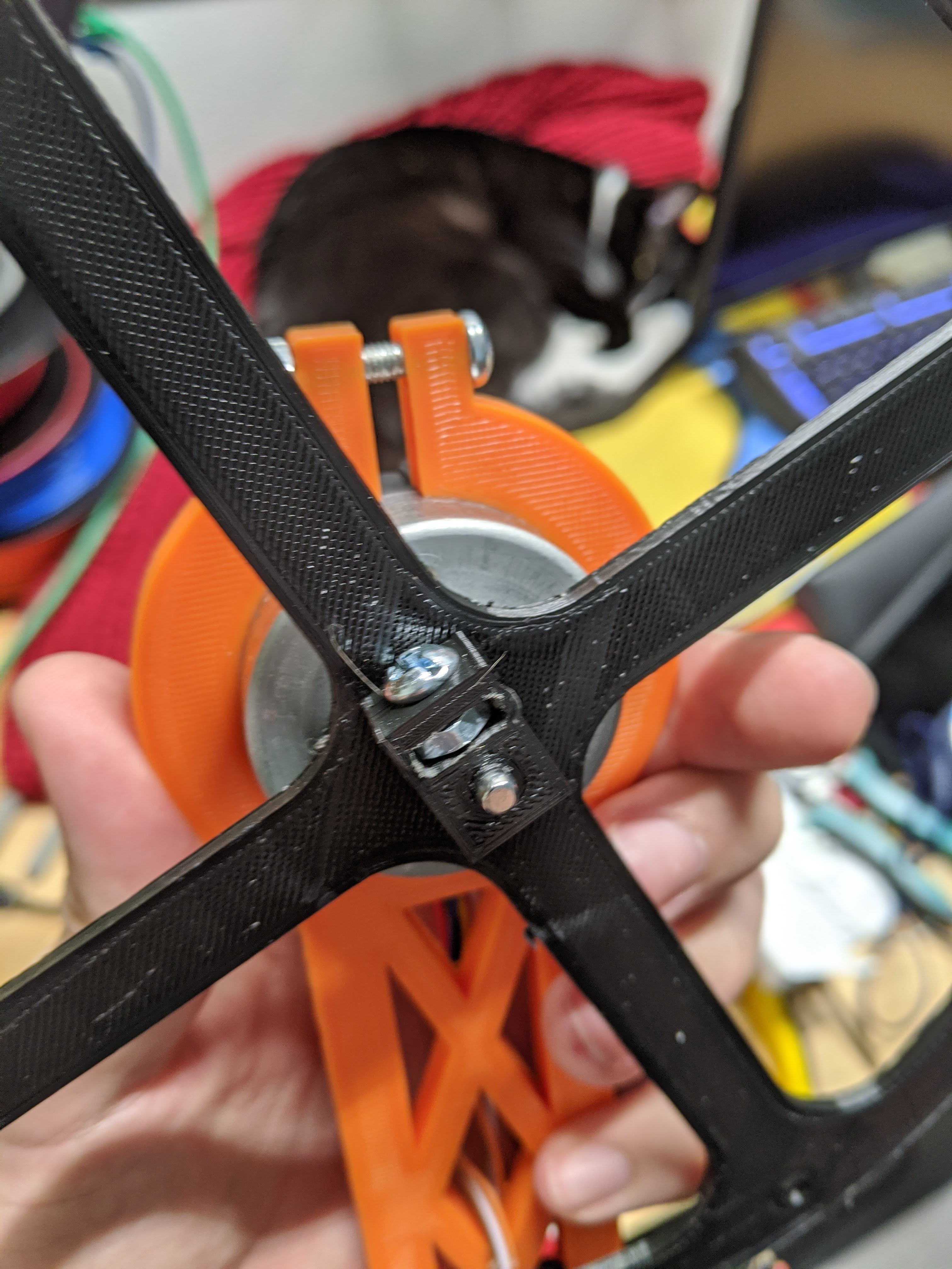
To keep the flywheel from flying off, made just the sort of screwy setup I can be counted on for:
![]()
Net-zero y-acceleration test (orange light blinks):
Swing-up gumption test (bonus: near loss of life or limb):
Very happy to see that the PLA placeholder wheel was sufficient, not needing to get a metal wheel machined was a load off my plate.
Next:
Implementing the PID controller.
-
Mk II
12/31/2019 at 01:12 • 0 commentsOverview
Before the video thumbnail gets your hopes up - no, it does not work.
Swings pretty nice though. There is no motor action occurring here.
In this iteration, the pendulum is mounted away from obstructive surfaces through use of a right angle clamp and dowel.
Not yet programmed (but pictured) is a Teensy 4.0 with a familiar module - the MPU9250 Accelerometer/Gyroscope. The Teensy 4.0 boasts a 600 MHz controller, much beefier than the Arduino Nano (16MHz) used on Mk I.
Not pictured (and never to be) is an L298N motor driver for the BLDC motor. I've learned through a few posts on Hackaday not to be afraid of using more recent technologies to drive the motor, so for the next iteration I will be using the TB6612 or MAX14870 modules which are lighter, smaller, and more efficient than the L298.
I 3D printed a wheel of the desired radius, which I have attached to the motor until I can get a steel wheel fabricated/cut. With luck, the print will suffice in terms of mass.
Why not continue with the Mk II?
To power the electronics while the rig is spinning, I was counting on a fragile and hacky slip-ring substitute.
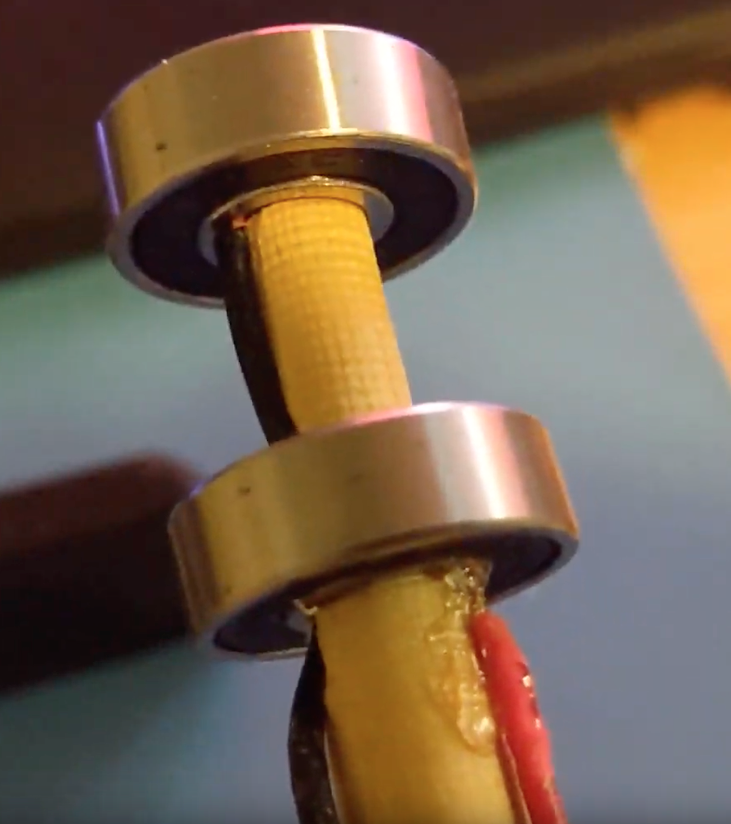
As pictured with the red wire, I squeezed a wire end between the wooden dowel and the inner wall of the bearing. The ball bearings separating the inner and outer walls are conductive (with these bearings but not with all bearings, I've found). Another wire squeezed between the outer wall and the PLA casing of the pendulum would complete the pathway. This would (theoretically) allow complete 360 degree rotation of the outer wall without breaks in electrical connection. I would put an LC circuit on the pendulum board to smooth out the supply.
The benefit to this kind of slip ring is that you can put solid axle directly through it. Traditional (cheap) slip rings don't have such a convenient hole through which to place a rotating rod (see Amazon product listed here).
However, I found no method of securing the wire to the bearing walls that withstood more than a gentle tug. As such, the play of the bearing and wire were enough to cause intermittent drops in power while the pendulum swung. I would likely need to spot weld wires onto the bearing walls for them to truly hold - I don't have such equipment.
Next Iteration
I will be purchasing a legitimate two wire slip ring and redesigning the pendulum and offset rod (clamped) to house it.
I have told myself this before, but never again will I use perfboard to prototype - I did it again for the Mk II and suffered for it just like every other time. I will lay out the PCB and have a few ordered this time.
-
Mk I
12/03/2019 at 01:48 • 2 commentsOverview
Mark I was cobbled together in the sum of a weekend. Having improper materials at hand, and having forgone any calculation whatsoever, I had healthy reason to doubt this initial incarnation. Shortcomings known, it left my mind free to build something with no expectation whatsoever.
The prototype employs some PLA mounts, a wooden dowel, some spare rotary pillow bearings, an Arduino Nano, an MPU9250, and a L298N motor driver. Excepting the PLA mounts, all components were rescued from a box of deceased projects.
Motors
Through the course of experimentation, I went through three different motors.
The first was geared, high RPM, low torque. During a brake or direction change, the inner metal teeth of the motor were shredded smooth over time as they resisted the inertia of the heavy spinning wheel. I needed a motor that could rapidly stop and change direction without damage. I decided to leave behind geared motors and try brushless DC.
The second motor was a BLDC with a built-in IC, hall sensor, and braking mechanism. Unfortunately, I too brusquely reviewed the specifications and missed an all-too-important line: "CW only, do not attempt to reverse polarity!"
The third motor was BLDC, high torque, low RPM. Torque is exerted by the motor transitioning from a standstill to full RPM (accelerating) while overcoming the inertia of the pendulum itself. The effectiveness of this torque is felt most strongly when the pendulum is nearly balanced. However, at angles of 15 degrees or more, the weight of the combined motor and wheel masses at the end of the pendulum lever arm becomes too much to overcome.
It also seems that, to hop up, I would see more success reaching a high RPM and slamming the brakes (high angular deceleration yielding high torque), the way the balancing reaction wheel cubes work.
PID Control
Additionally, the PID control software running on the Arduino appeared sluggish. Potentially the Arduino is not a high enough clockrate controller for this application.
Some more hardware-level calculations for this might be in order.
Plans for Mk II
- Do math.
- Mount the pendulum out away from the table so that it can perform 360 degree swings, and swing-up maneuvers, without hitting the desk from which it is mounted (swinging parallel to the desk edge).
- PID software currently does a running average to remove noise. Possible to program the noise floor on the MPU9250: MPU-9250 Datasheet
- Wheel will be larger in radius but lower in mass.
- Note equation of inertia for a disk:
- Note equation of inertia for a disk:
- Increases to the wheel radius will increase a spinning wheel's inertia (and torque) exponentially.
- The masses of the wheel, motor, and pendulum collectively have inertia, which we are attempting to overcome by spinning the wheel. A lower wheel mass will decrease the inertia of the inert motor/wheel assembly on the end of the pendulum, making it easier to overcome with high spinning torque of the wheel.
- Steel wheel cut with OSHCUT services.
- The P, I, and D constants will be communicated remotely to the on-board controller (and stored periodically in EEPROM) using NRF24L01 breakouts (one of which is already on Mk I in the video).
- Possible switch to a multi-threaded, higher clockrate device to process wireless communications and PID control simultaneously.
Reaction Wheel Pendulum
A self-balancing inverted pendulum with swing-up capability.
 A.M. Smith