 Joshua Brewster
-
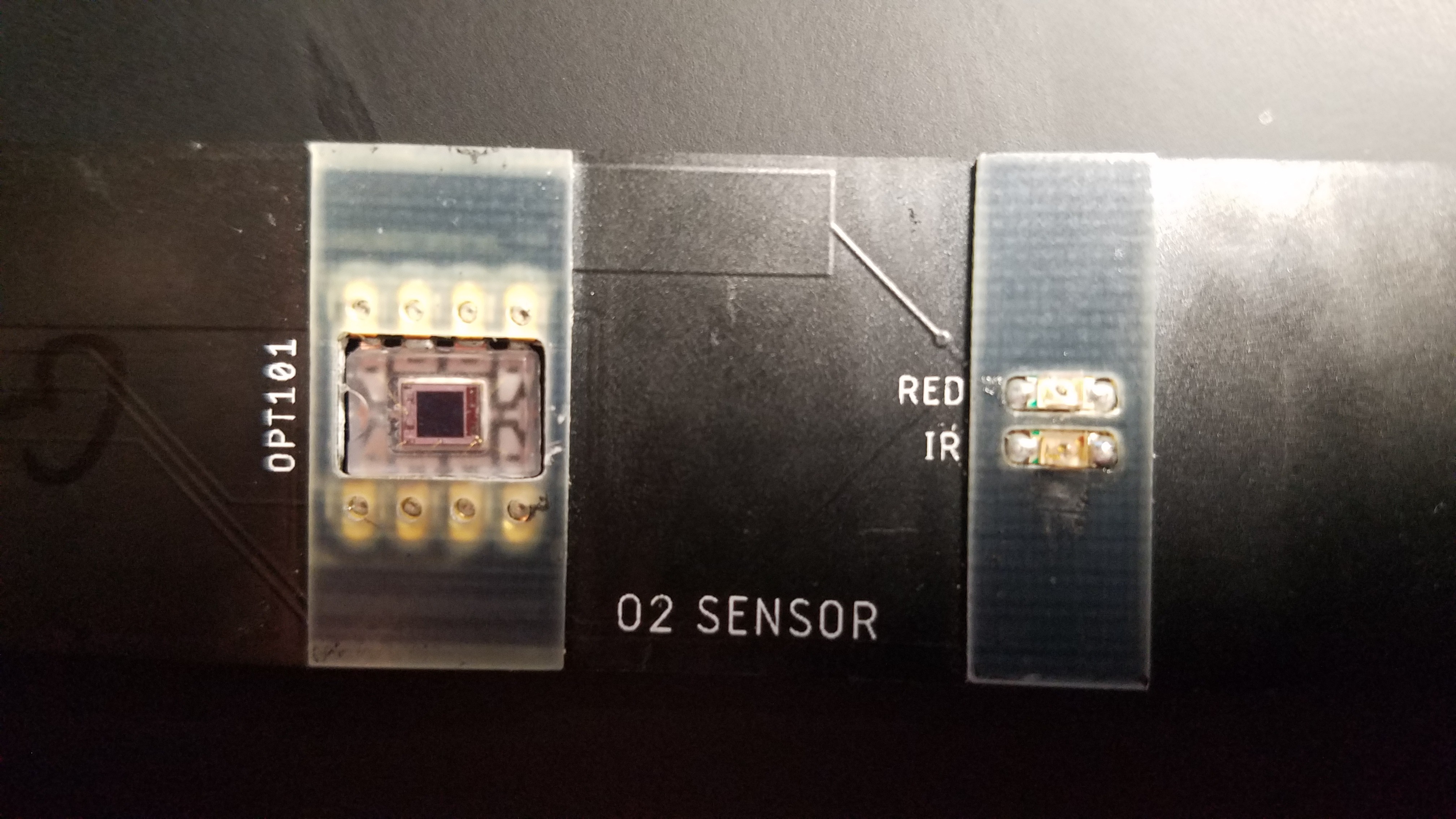
1Sensor: OPT101
Place the OPT101 through the hole from the backside where the solder pads are exposed. Make sure the notch on the OPT101 is facing the 6p6c connector direction. Solder it down so it is about flush with the stiffener on the face.
![]()
-
2Sensor: LEDs
The LEDs have tiny green notches on them. Put the Red and Infrared LED in each of their respectively labeled positions with the green notches facing toward the 6p6c connector (direction also marked by little white notches on the PCB). If you forget which LED is which you can always get the Red one to visibly light up with a multimeter set to Diode mode.
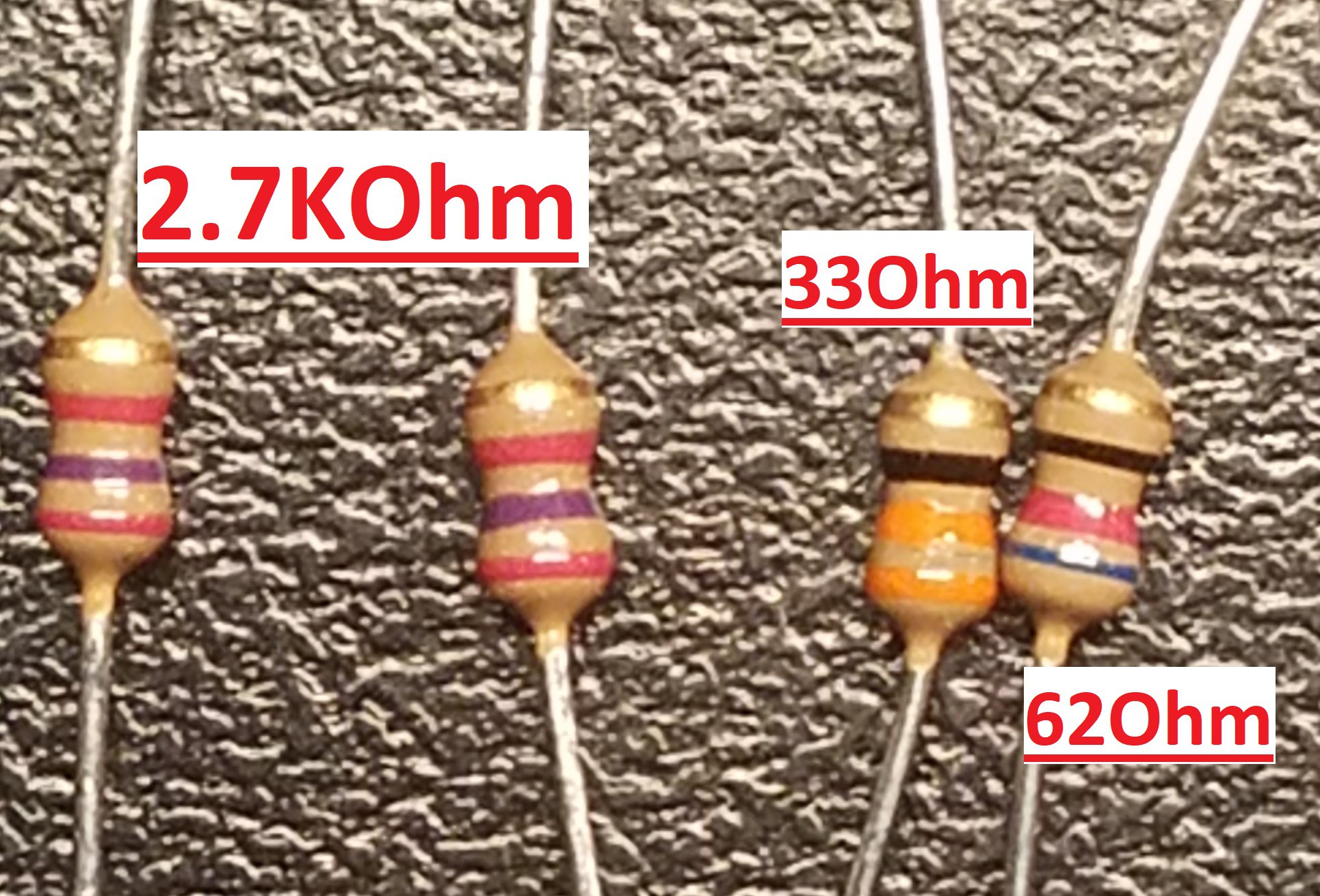
Add the 33 ohm resistor to the 62 spot and the 62 ohm resistor to the 470 spot. We had to lower the resistance on the IR LED due to sensitivity issues that cropped up on lower power settings. Make sure the resistors are on the back side facing away from your head so it doesn't feel awkward. Clip the leads. Finally, add the 6p6c connector to the correct side.
![]()
![]()
![]()
-
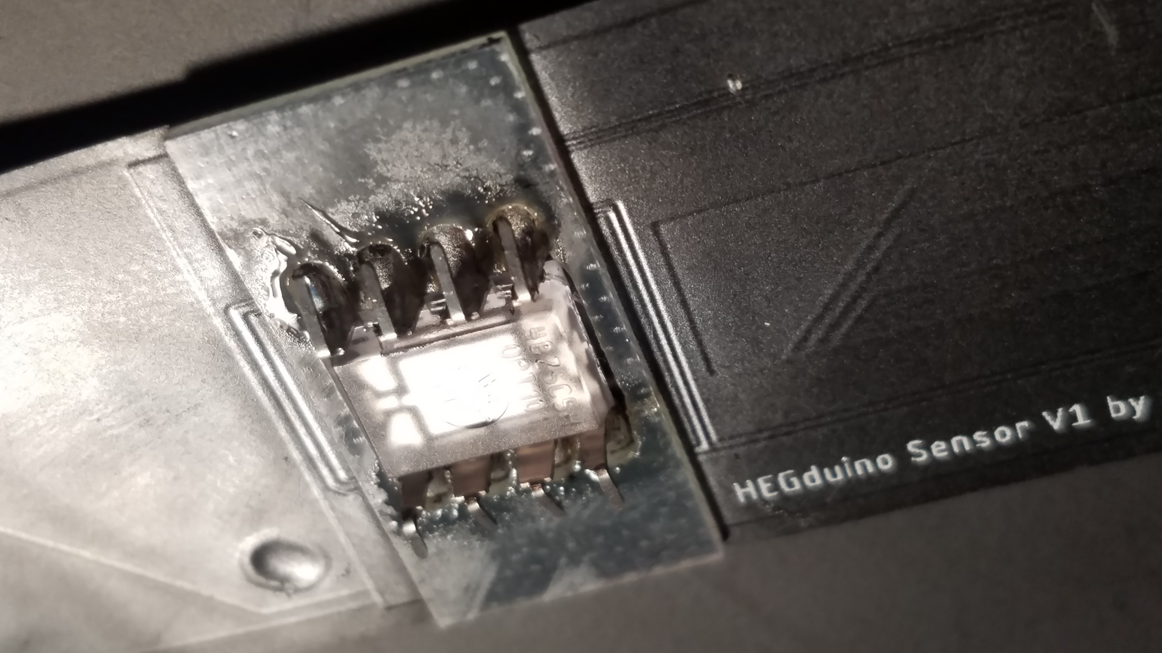
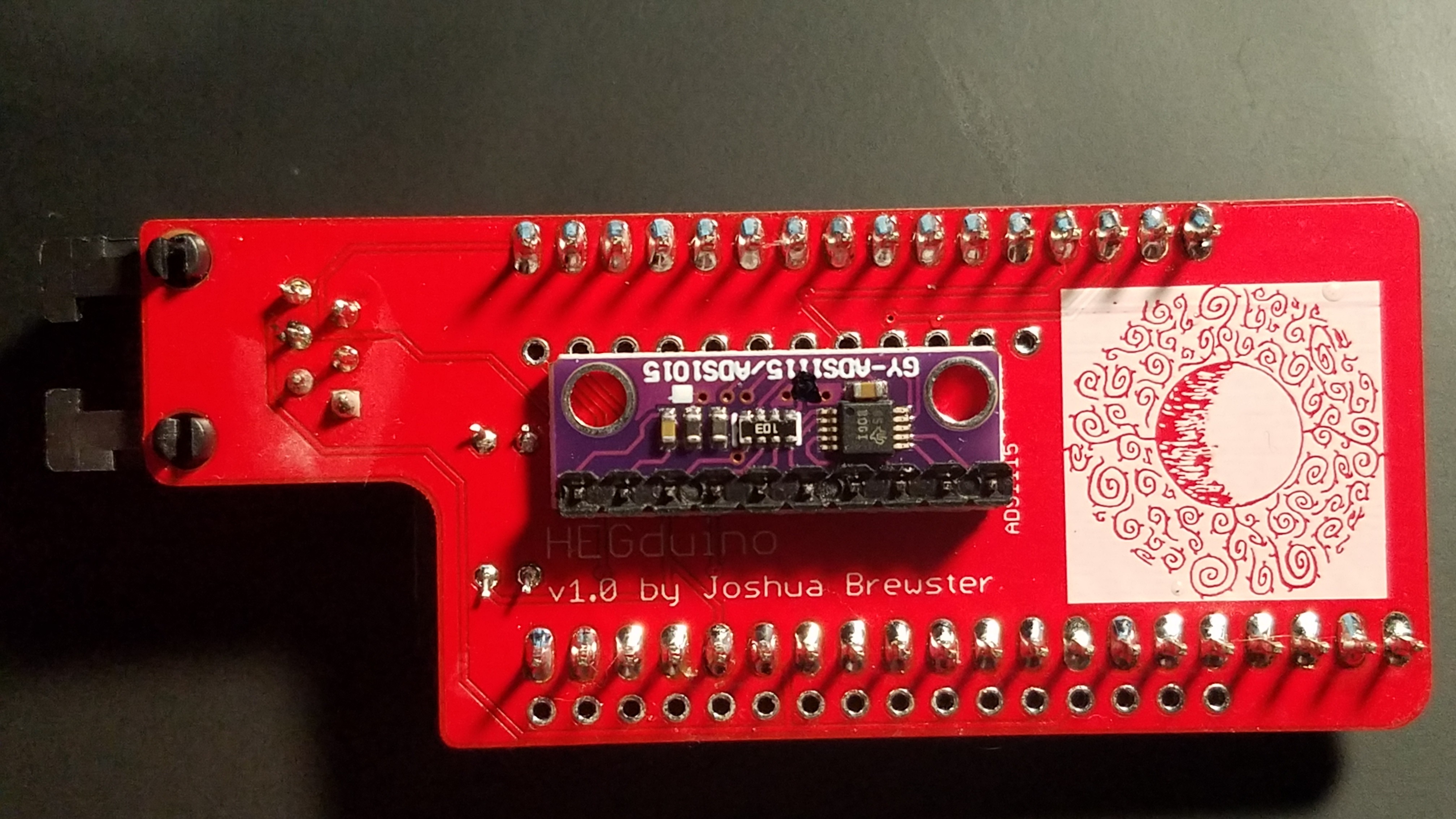
3Microcontroller assembly
![]()
This part is fairly self explanatory as everything is clearly labeled. First add the 2.7kOhm resistor and the ADS1115. The ADS1115 has clearly marked VDD and A0 pins to indicate the direction it should be placed on the hub board. Clip the leads to make room for the ESP32 on the other side. Do this first because it won’t easy to add these after the ESP32 is soldered.
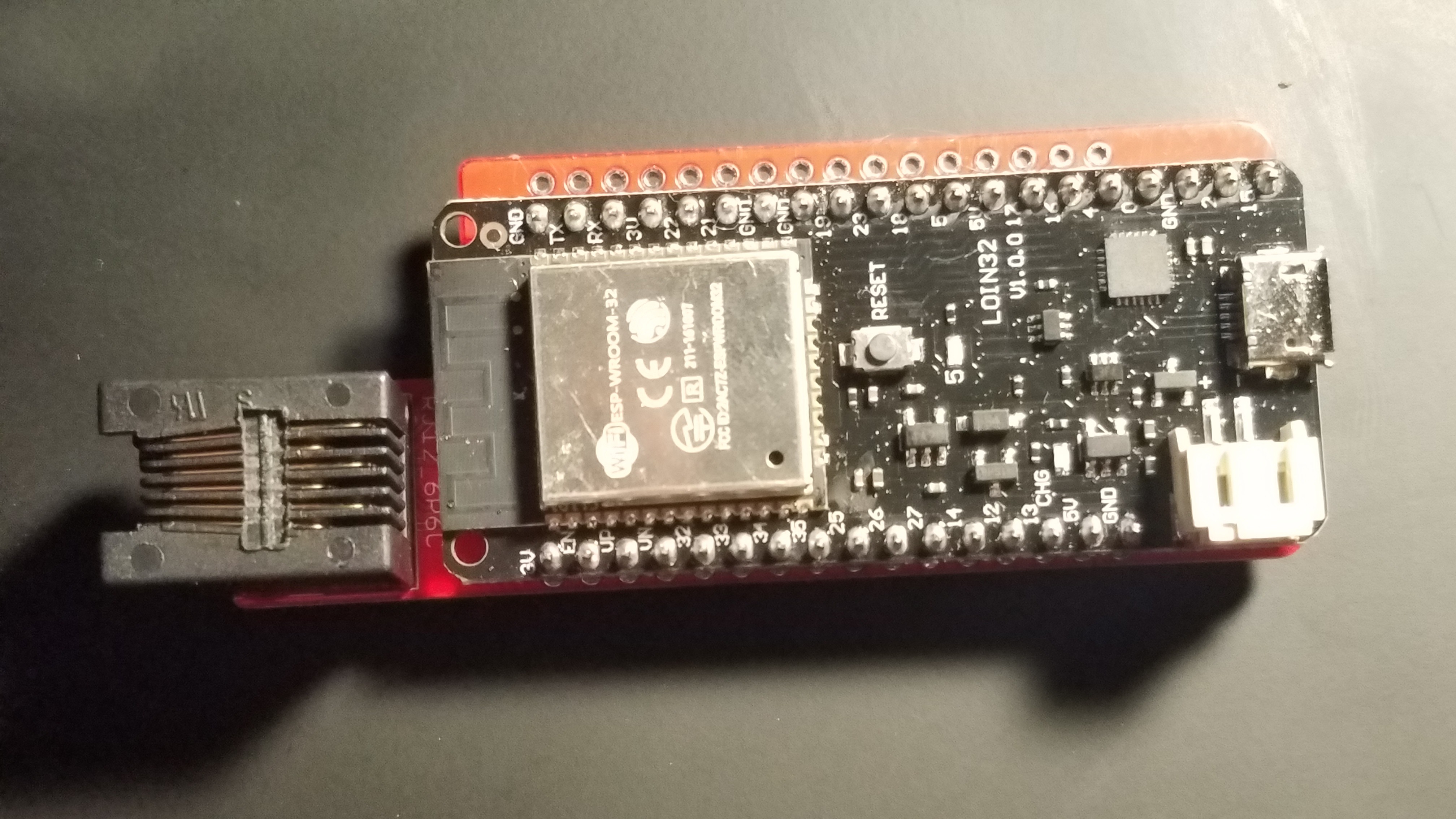
If you are using a Huzzah32 form-factor board, the ADS1115 comes pretty close to the pin holes (sorry!) but just make sure you’re not completely covering them with the ADS1115. I recommend putting the pin header for the ADS1115 through the top of the ADS1115 to minimize the form factor. After soldering these parts, clip the leads as short as possible. There are 2 compatible popular ESP32 boards, the LOLIN32 and Huzzah32 Feather, that only fit in their respective slots on the correct side of the PCB, go ahead and add it, then finally add the connectors. Lastly, optionally, cover it all up with electrical tape to prevent shorts or static damage.
![]()
-
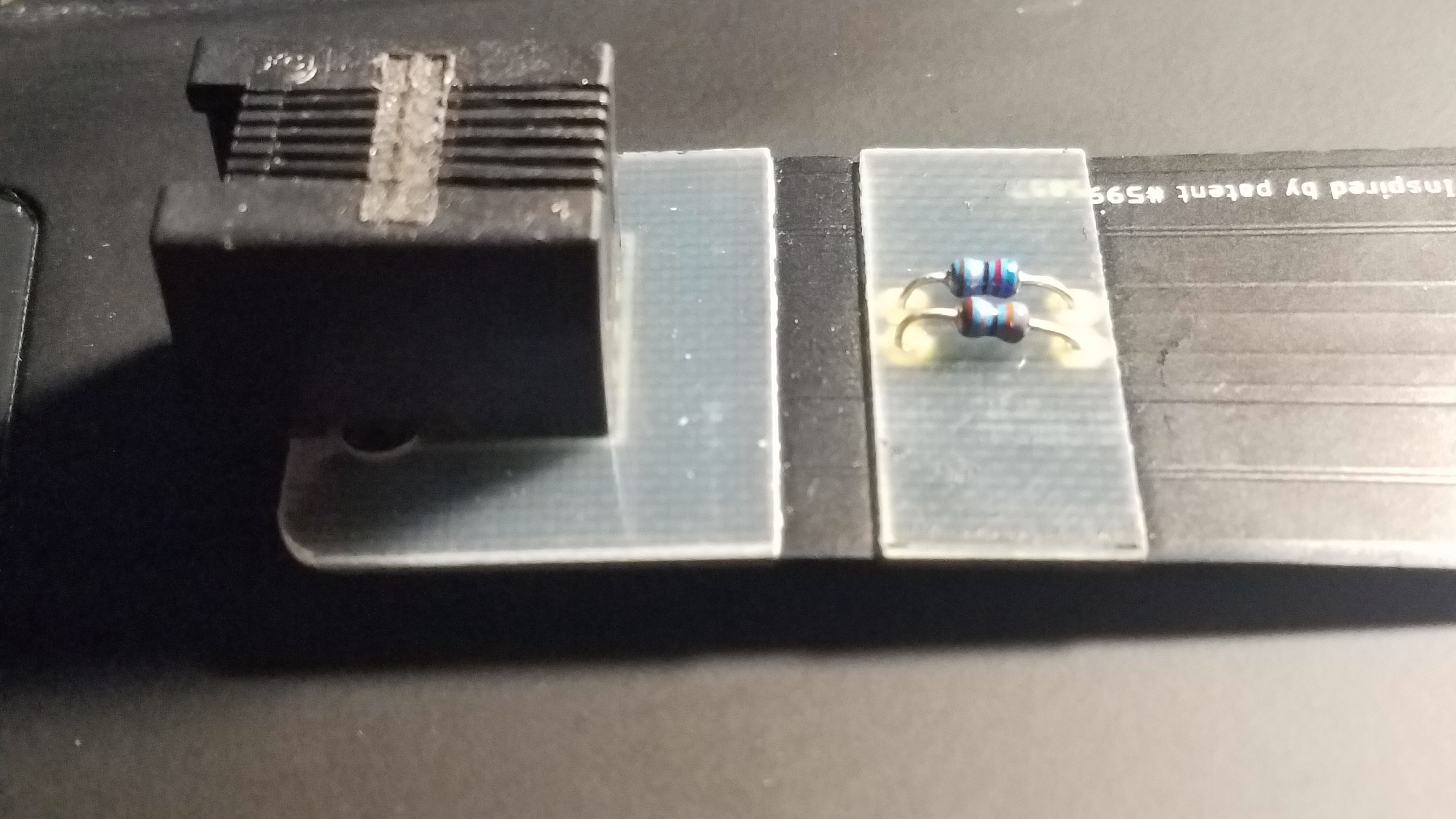
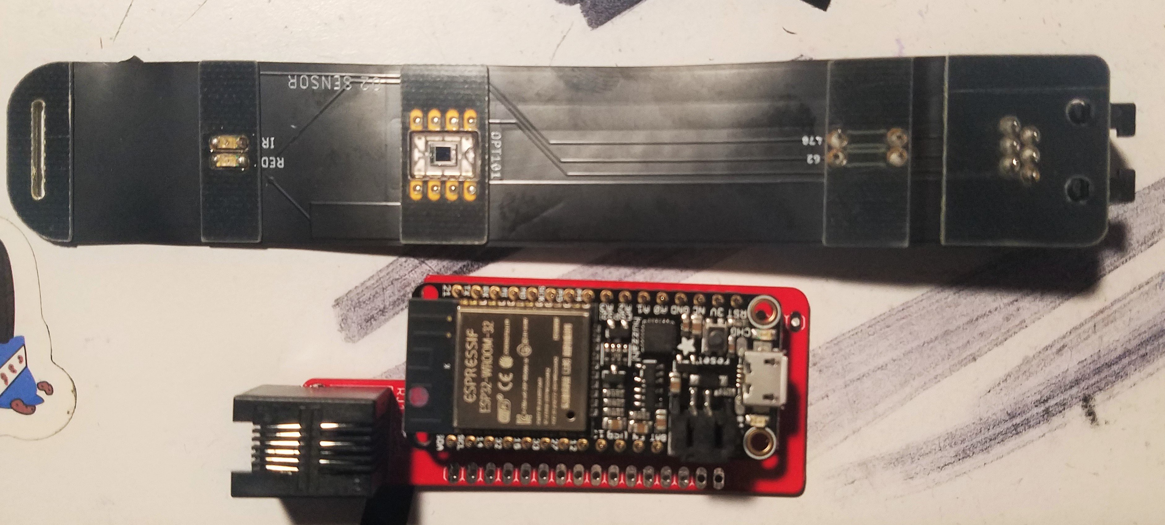
4Connectors (Optional)
There are 2 6p6c connectors that can be used to give your sensor a cord and make the microcontroller placement more flexible. The pinholes are clearly marked and only fit in one direction.
You can also connect the connector pin holes on each PCB together directly on the correct-facing side for a shorter but more reliable HEG setup since the cord can be finicky. For this you just align the pins so the sensor is facing your face and the microcontroller is facing away and use standard pin headers to solder them together.
![]()
![]()
-
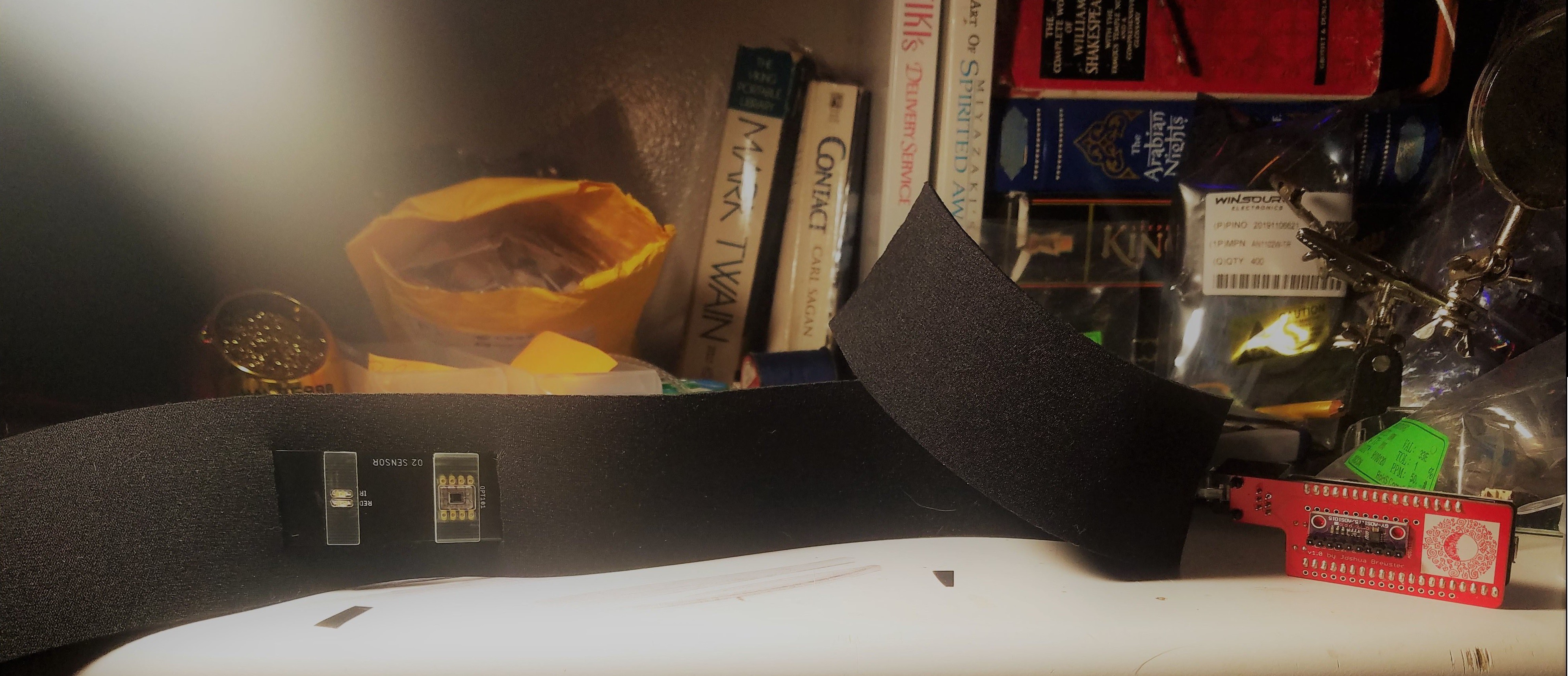
5Plug it together then plug it in to your computerWith your HEG pieces assembled and connected, voila - an experimental biofeedback device! Go ahead and plug it into your computer and see that a light flashes on the board. You can get the firmware from https://github.com/moothyknight/HEG_ESP32.
-
6Setting up Arduino
You need the Arduino IDE, the ESP32 libraries (use the developer libraries rather than the boards manager version so these are modifiable), as well as all of the additional libraries and steps listed in our readme.
When that's all set up, if you followed our readme correctly, you should be able to simply open the sketch we provided and hit upload (ensure your Board is selected as well as the partition scheme “Minimal SPIFFS (Large Apps with OTA)”). Check the serial monitor output and try the command "D" to test the sensor and "f" to deactivate it - or just hit the reset button on your board.
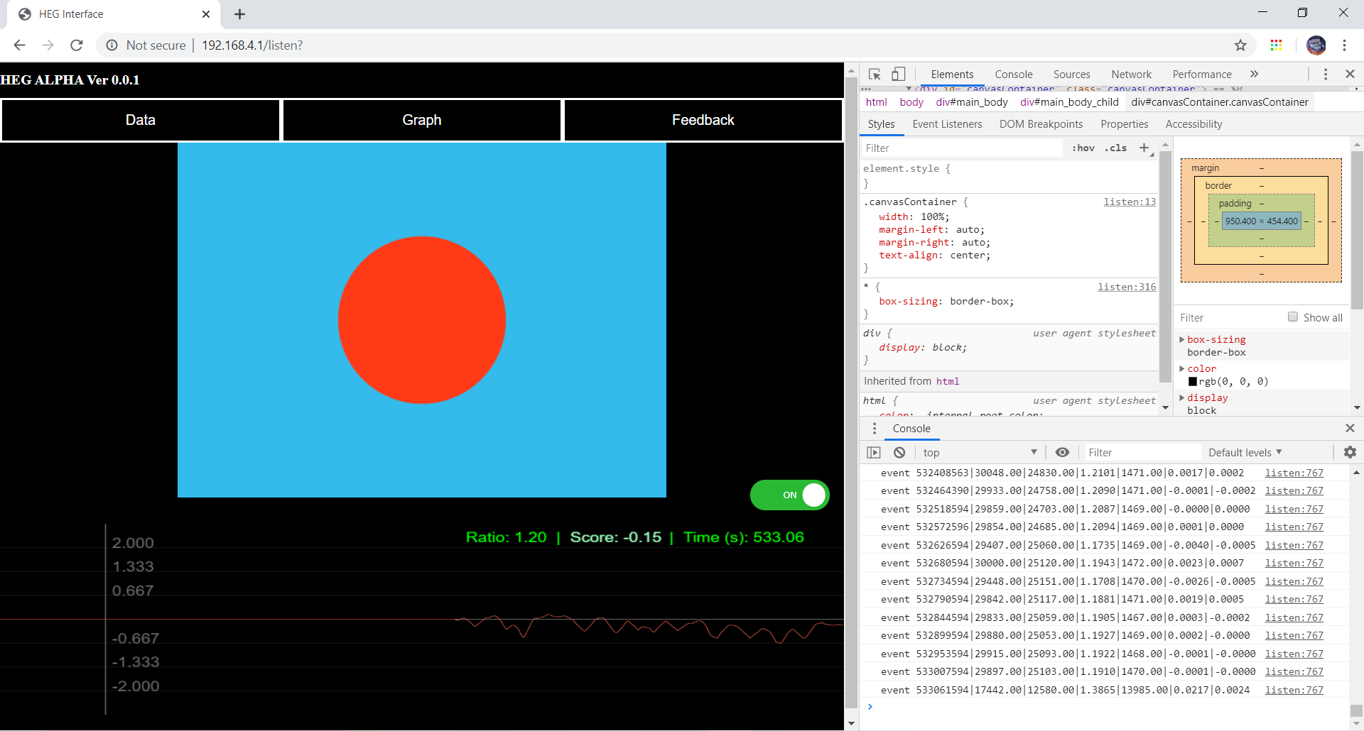
After that, you should find SSID "My_HEG" in your WiFi connections list, connect with password 12345678, go to 192.168.4.1 (or http://esp32.local on Apple or Bonjour-enabled devices) via your browser, and check out our on-board demo thanks to the ESP32's awesome web capabilities! Works best on Chrome and Firefox. This is all a work in progress and will be updated for months to come, so keep an eye out by Watching our Github repository!
![]()
Discussions
Become a Hackaday.io Member
Create an account to leave a comment. Already have an account? Log In.