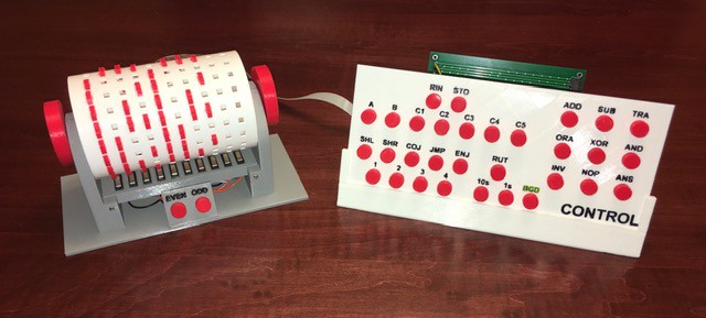
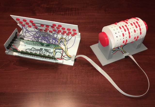
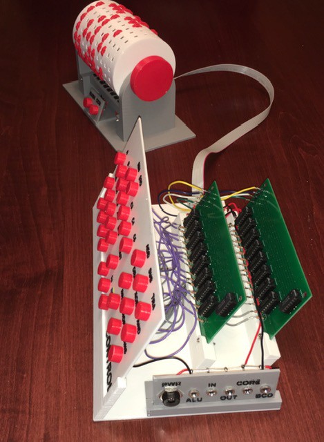
Just finished wiring and testing the Control Panel. The wiring got a bit hairy but it works well.

I used a 10 lead ribbon cable to connect the Drum Instruction Memory to the panel itself. Two leads were for power and the other 8 were for the op code and address control bits (4 for each). The drum base has lights marked Even and Odd hooked up to the two timing switches. These will alternate between instructions to give a visual indication that you have move to the next instruction correctly. You could also have both on to indicate the first line of the program and both off for the last line (say).

Lots of wire but the two 4 to 16 decoders basically just map the each op code and address to a single indicator light on the panel. There are 31 LEDs in total. I guess you could say this is WDC-1's instruction decoder.

The Control Panel is also where the power comes in and gets distributed to the other components of the machine. I'm using 3.5 mm stereo jacks and plugs so that the various pieces of the machine can be easily disconnected for close examination.
As I was setting up the power I also decided to make another small change from the book. The power "Junction Box" in the book was set up to power the components only when they were being used for part of an instruction. So for the command:
RIN Address Afor instance only the ALU and the Input Panel's Encoder A part of the machine would be enabled. This might provide a little extra clarity when executing instructions, but prevents a demonstrator from just showing what each part of the machine does in the absence of the proper commands. So I have decided to keep all of the modules powered all the time. I have not closed the door on the book's method, I can easily rewire for it, but for now I'm going with always on.
 Michael Gardi
Discussions
Become a Hackaday.io Member
Create an account to leave a comment. Already have an account? Log In.