 Michael Gardi
With all of the major components complete it's time to put it all together. I attached a 3-wire power cable with a 3.5 mm stereo plugs to each of the peripheral modules.
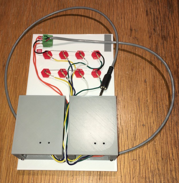
For the Input and Output panels the extra power wire would allow me to selectively power the Encoder A, Encoder B, 10^1, and 10^0 elements independently should I choose.
After that there was nothing left to do but plug it all together and power it on.
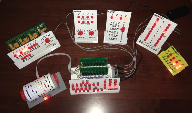
Ready to go.
Discussions
Become a Hackaday.io Member
Create an account to leave a comment. Already have an account? Log In.