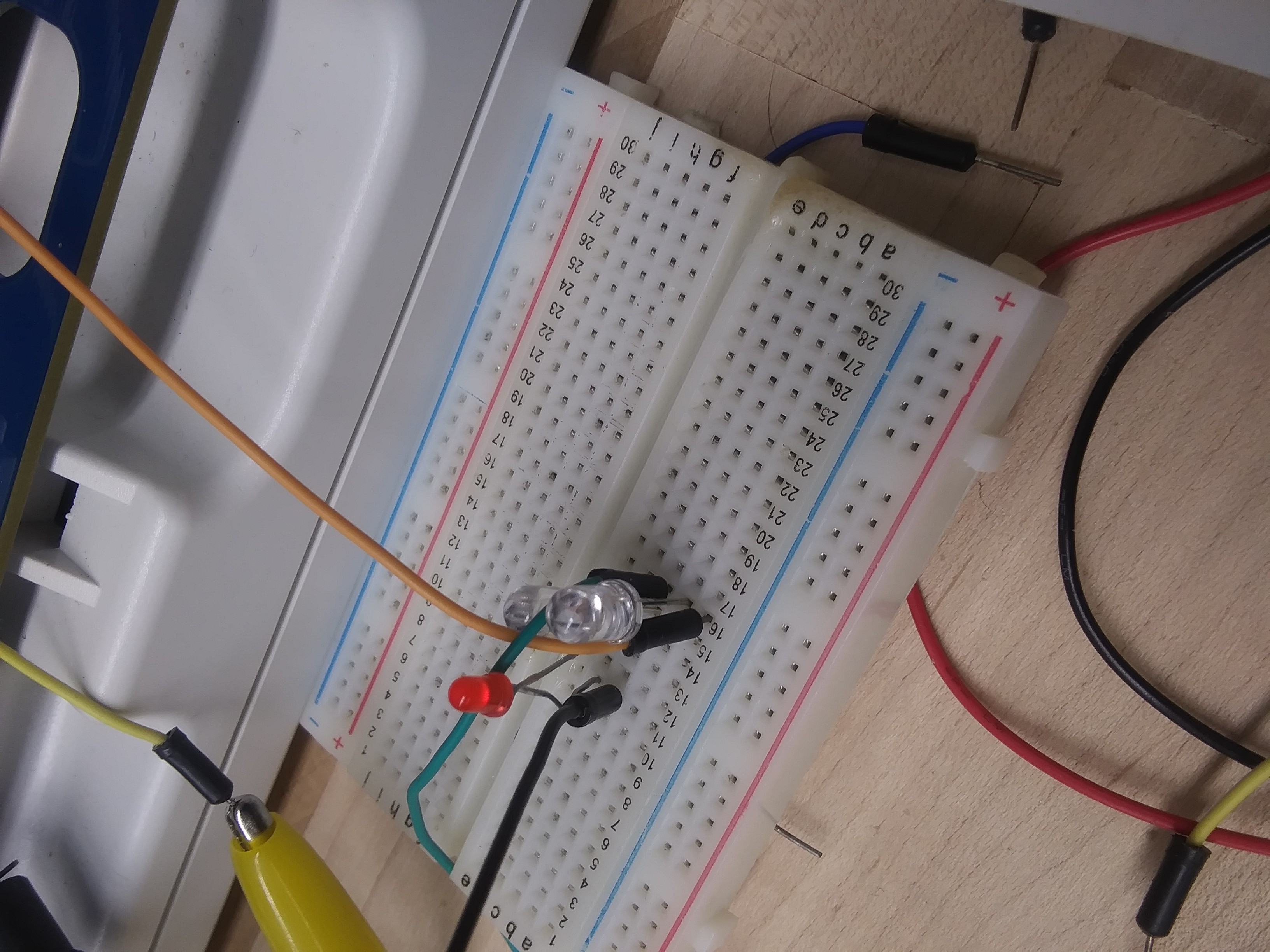
The next 1.5 hours (after lunch) were spent applying this information. This time, in our circuit diagram, we were able to see patterns like port 2 and port 6 are connected together and then connected to ground. We missed this the first three times we wired up our circuit.
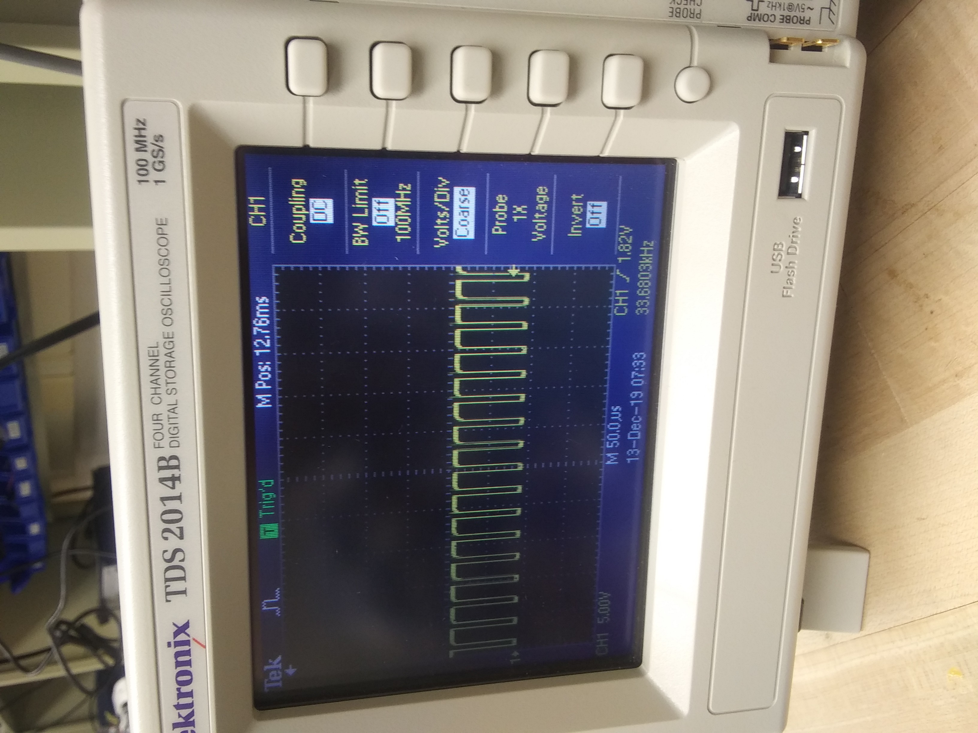
We knew how to set up the oscilloscope and it was sensing the circuit. This way after we created the TV jammer, we knew where to place the sensing probe. And the frequency was 33KHZ! If we twisted the potentiometer, the frequency would adjust! This was working like we thought it would!

As seen in this photo, we hit 33.60 kHz.
We pointed this at the TV, but the TV remote still was able to send a signal. This was frustrating.
Our next steps would be to place the infrared bulbs in front of the infrared bulbs of the remote. That way the signal has to pass through our jamming signal first.
 Our infrared light bulbs that we know are sending out a signal.
Also, maybe nothing is wrong, and we just don't have the magic frequency that the TV and the remote respond to.
We'll iterate through all the khz values.
-Wajq
 wajqnosewicz
Discussions
Become a Hackaday.io Member
Create an account to leave a comment. Already have an account? Log In.