 J_Ray
J_Ray-
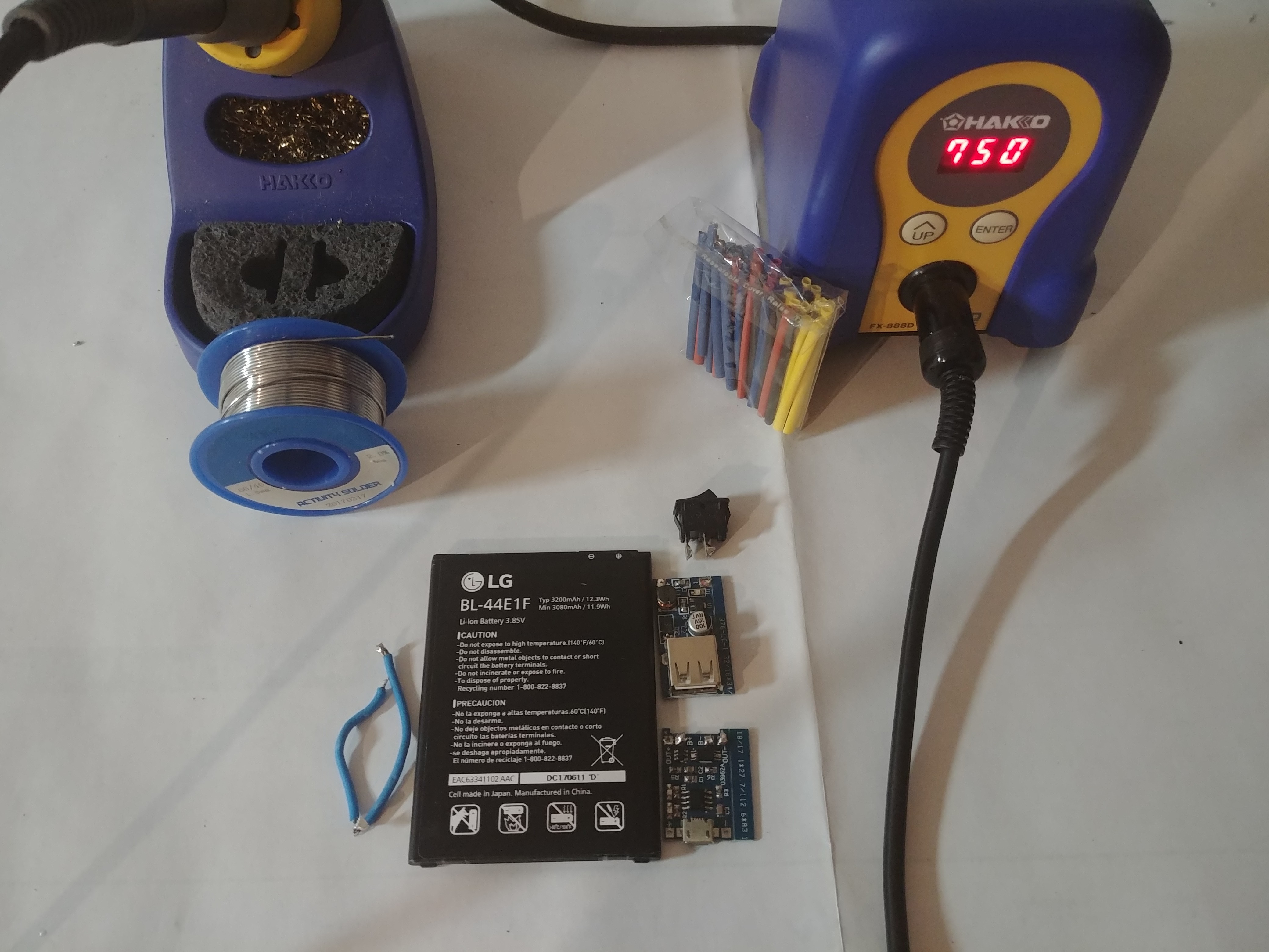
1Step 1:
First get all your parts together and turn your soldering iron on with a larger tip but still small enough to stay on the battery terminal as we do not want to melt part of the battery. Smaller tips will transfer heat much slower leading to either cold solder joints or to you heating up the battery. With the tip being on the battery terminal longer the heat will transfer into the battery and may cause problems such as a failure of the battery, battery swelling, and in rare cases the battery bursting.
![]()
-
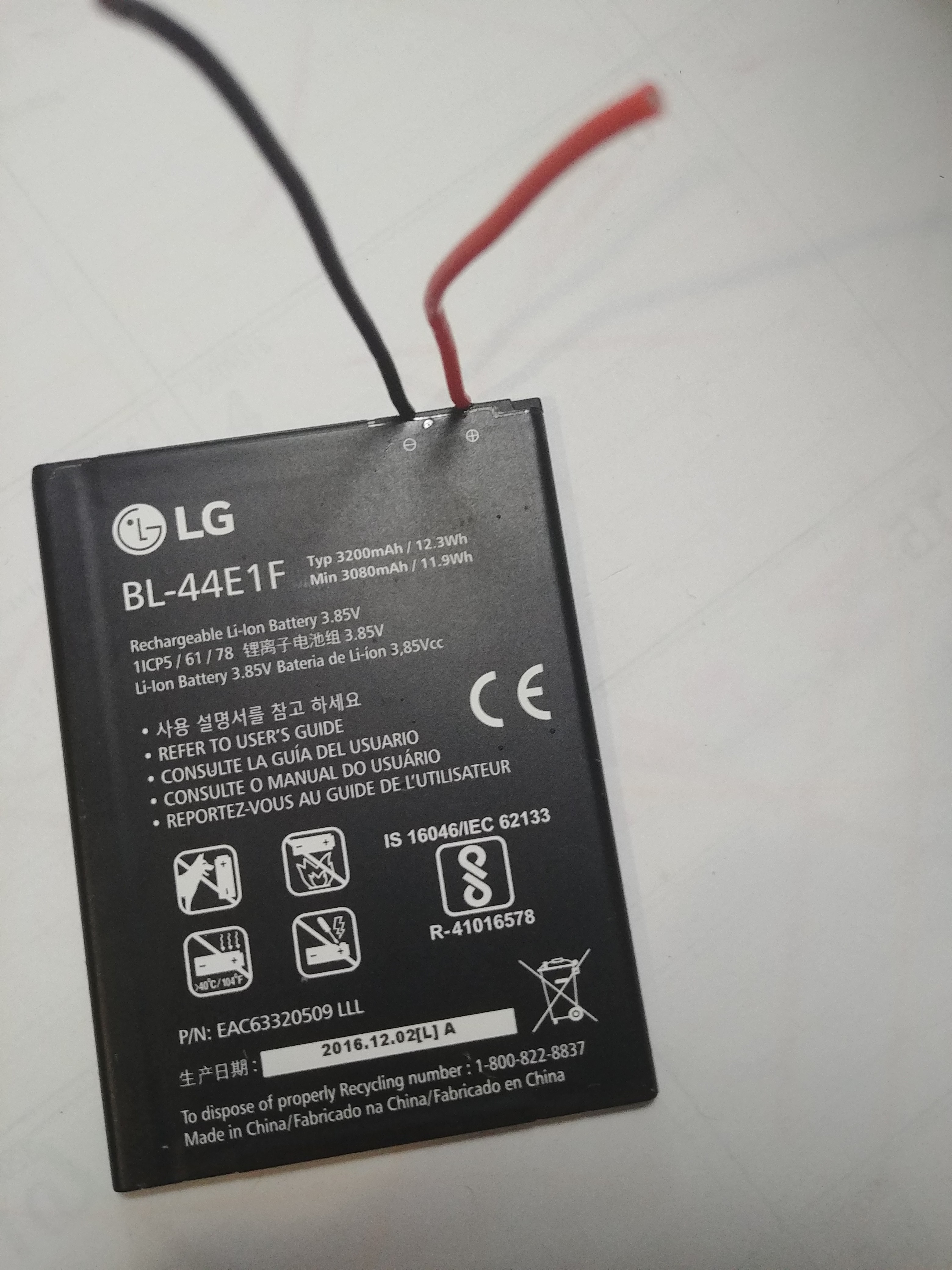
2Step 2:
We will begin soldering the wires to different components starting with the battery. Remember to tin both the pads of the battery you will be soldering as well as the wire. This will help to ensure good connections between the wire and battery. I will not be saying it for the rest of the project, but you should be tinning each side of the connections as this is just a good practice. We will only be soldering to the + and – terminal of the battery. Make sure you do not get solder on any of the other pads.
![]()
-
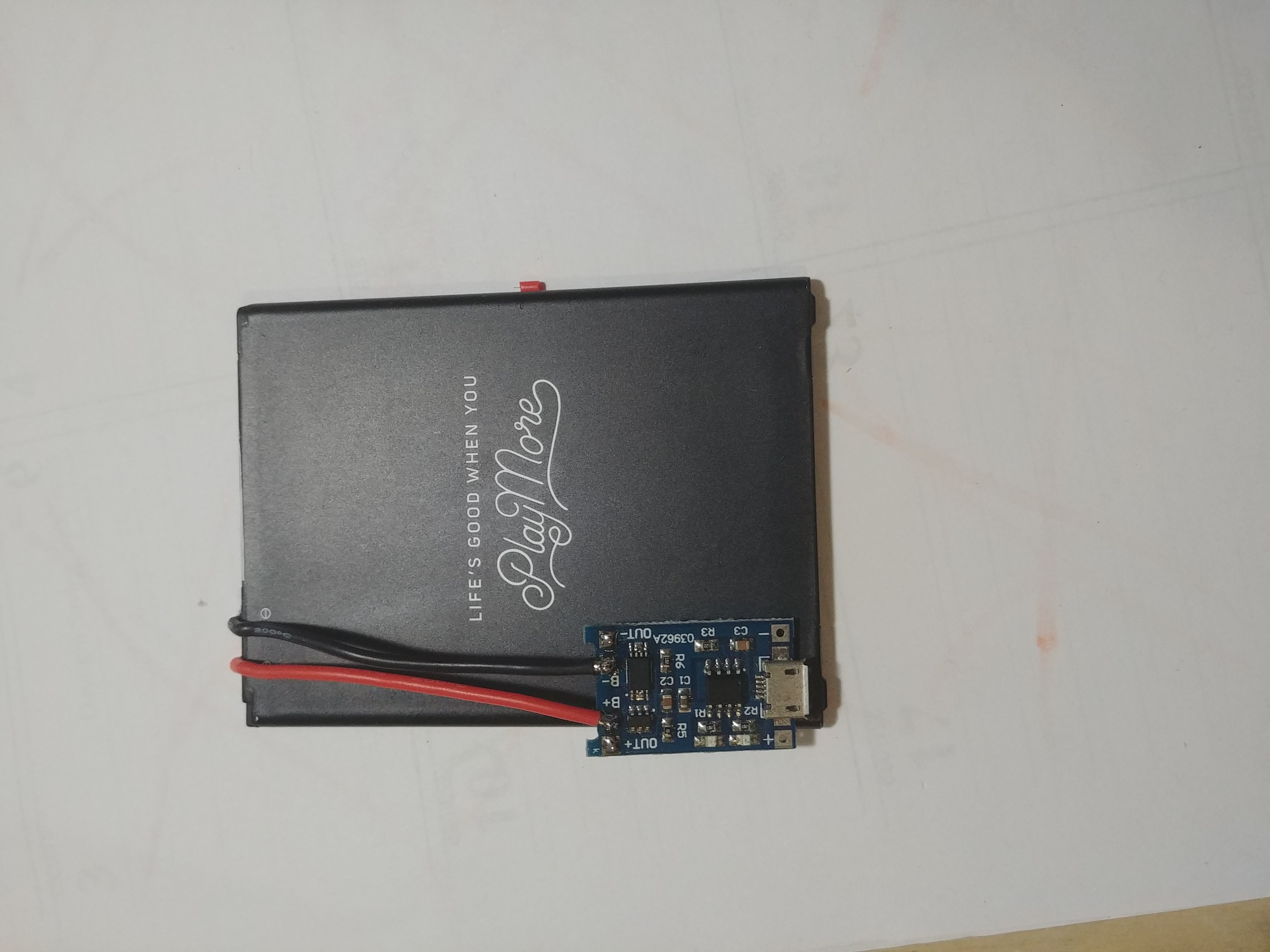
3Step 3:
Now, connect the positive terminal wire to the positive B (+B) and the negative battery terminal wire to the negative B (-B) terminal on the charger board.
![]()
-
4Step 4:
Connect two wires to the output pads on the charging board.
-
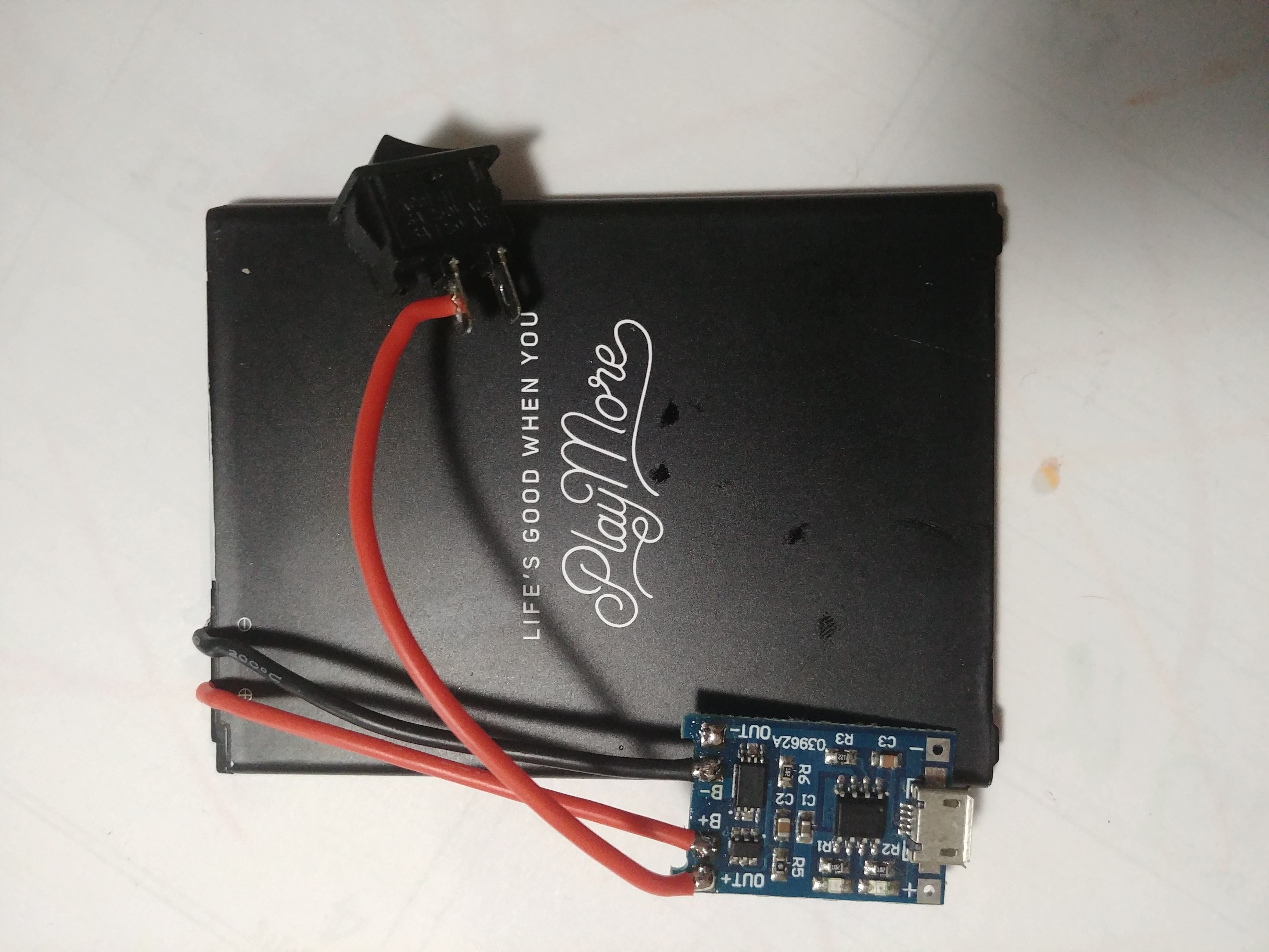
5Step 5:
Connect the wire you soldered to the positive out (out+) terminal to one of the terminals of the 2-pin switch. Connect the other pin of the switch to a new wire that will be connected to the positive pad (+).
![]()
-
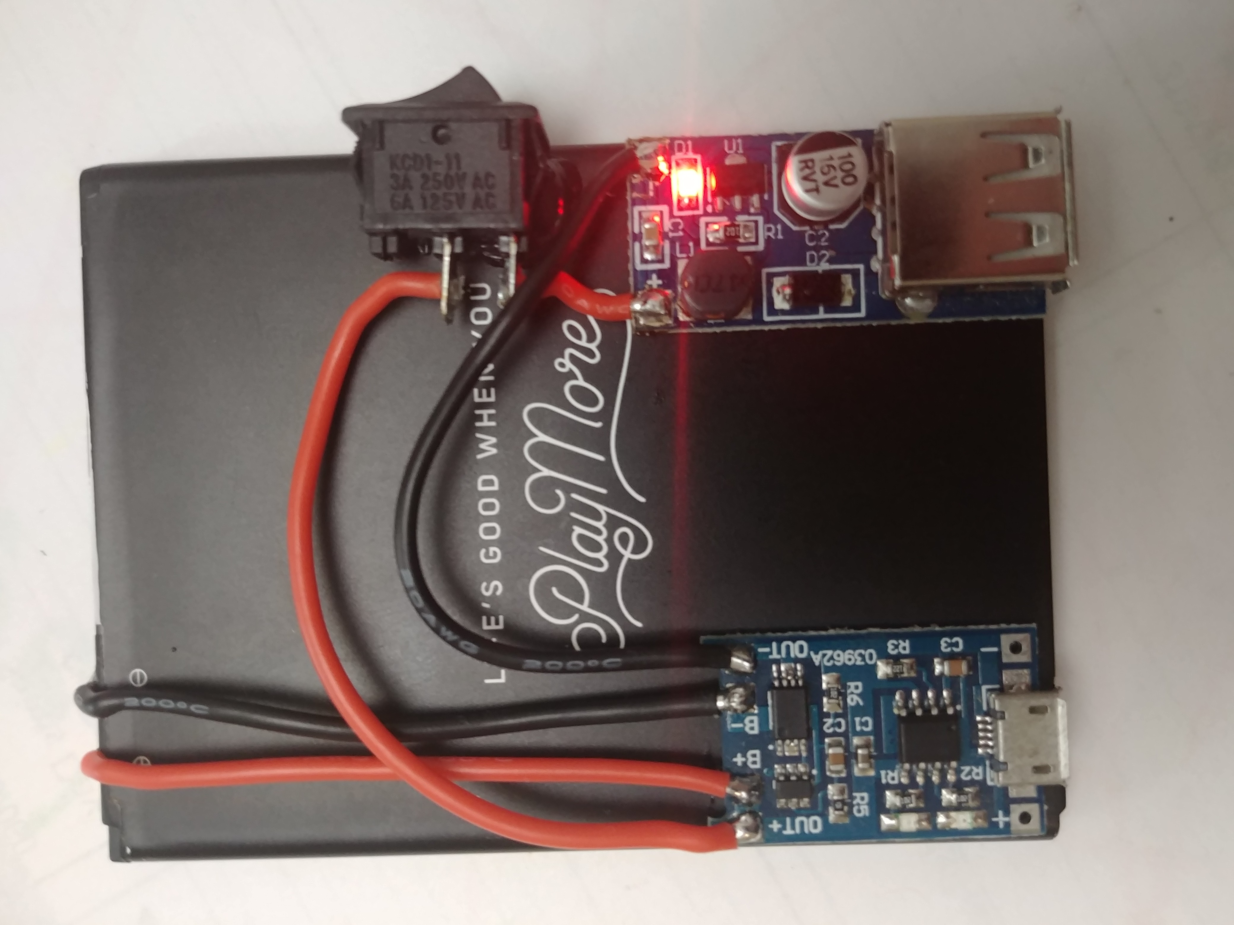
6Step 6:
Connect the negative pad of the power supply module (-) to the negative out of the charging board (out-). After you make this connection the project is completed the only thing left to do is to test the circuit. Do looking all your connection for any obvious bad connection or shorts, then switch the switch from off to on or 0 to 1. If you did this correctly the red led on the power supply module should turn on.
![]()
![]()
Cell Phone Battery Brick
A thin battery brick made from just a cell phone battery, on/off switch, charging module, and power supply module.

Discussions
Become a Hackaday.io Member
Create an account to leave a comment. Already have an account? Log In.