-
1Battery Build resources
HBPowerwall: https://www.youtube.com/channel/UC0pBauLp63yzf6sVdEOIUbA
(Good tutorial to follow along with for how to reclaim cells from old laptop batteries.) His whole channel
jehugarcia: https://www.youtube.com/results?search_query=jehugarcia
His whole channel
Both channels
-
2Step 1
Buy a board and ride it for a while. I know it may not be quite the same but learning to kick and handle speed wobbles proves itself invaluable when you are about to be thrown off. Just the balance and the intuition you get from the riding on a nonmodified board is well worth the time spent. If you even buy the board and then order components you will have about a month to practice which may not be optimal, but it will allow you enough time to learn the basics. Some notes for those of you wondering what board to buy. I would say to go with a medium flex board as it still gives a very responsive ride while still holding the components tight without making different soldering joints be constantly strained because of the flex you are asking from the battery.
-
3Step 2
Now that you are starting to receive components in the mail begin to lay them out along your board. Decide whether you want a low profile and tight to the board construction like I did or if you are ok with having a little more around the trucks to free up the middle of the board. While deciding the placement begin to think about the enclosure you want. I decided on a canvas cover as it allows for me to easily detach the battery and esc from the board in about 15 seconds and then the only thing different from my board and the original board is just the front truck and wheel assembly which can be switched out easily. This has allowed me easy maintenance to all the components and also allowed me to use the board when I had a esc failure and was waiting over a month for a new esc
-
4Step 3
When we have all our components, we should have already laid them out and know how we want them to fit on the board. With this being true, we can begin putting components together off the board to test as working in a more confided area, on the board, is just adding difficulty to the project.
-
5Step 4 (You nay not have to do)
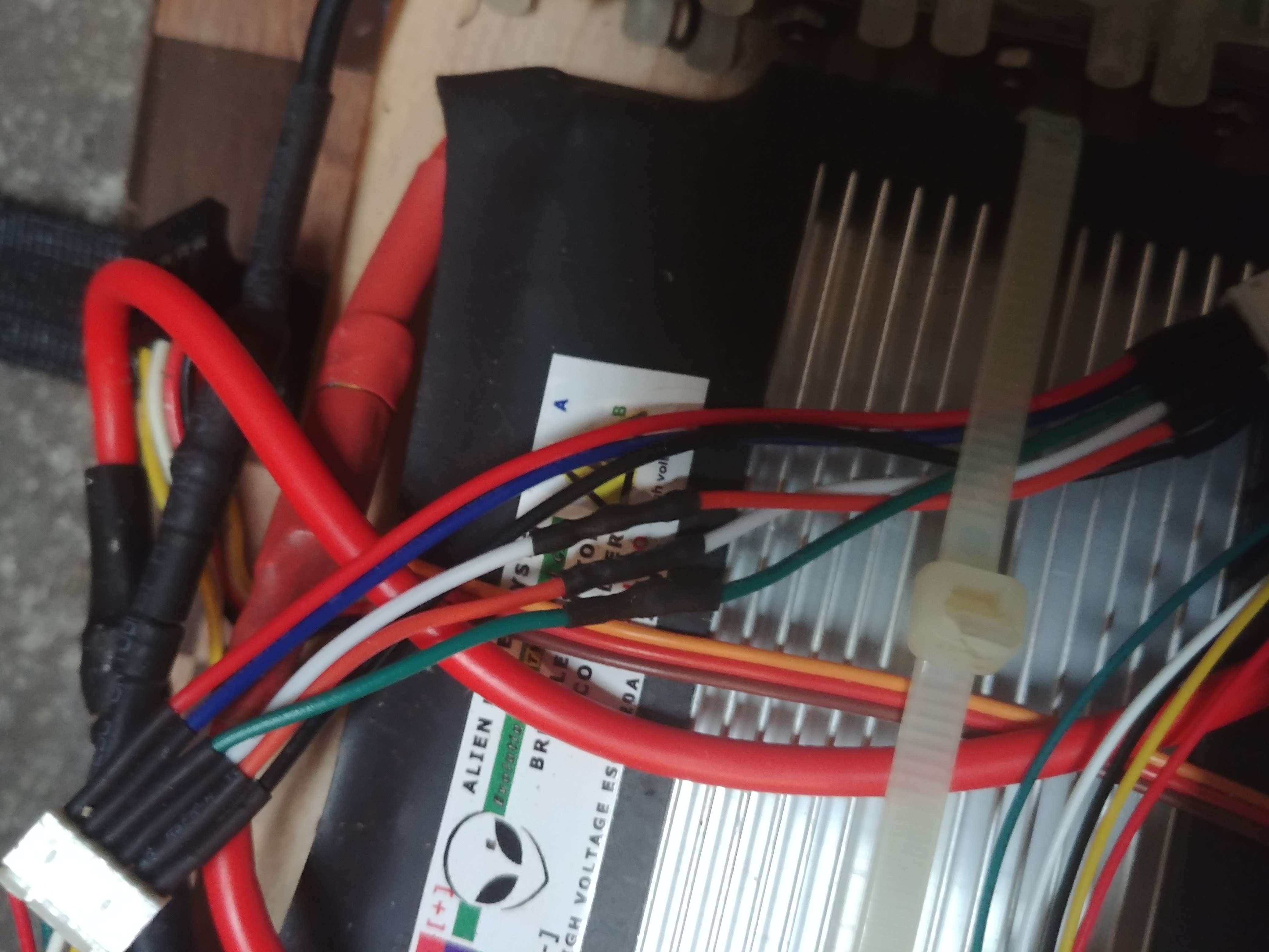
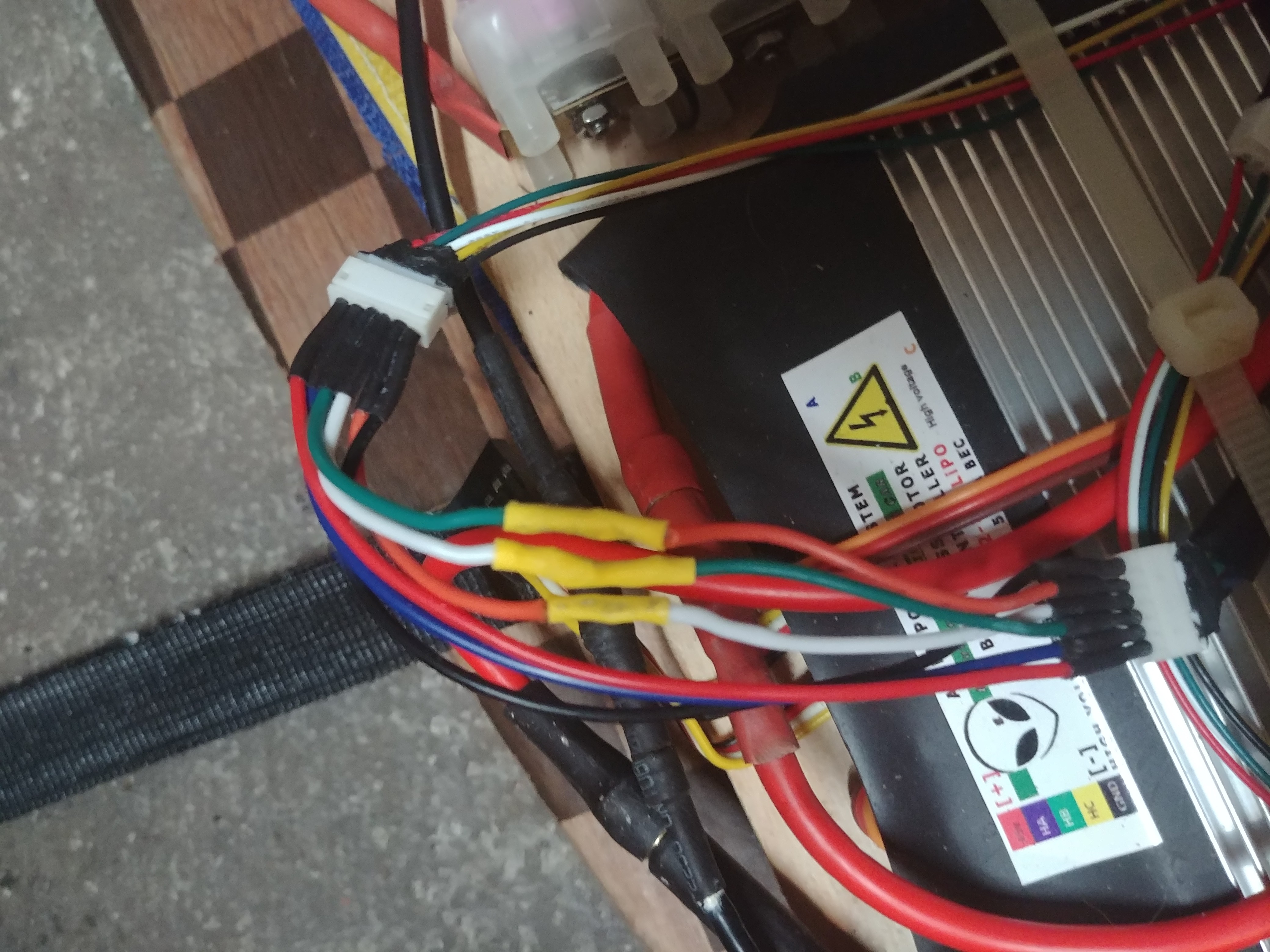
In this step we will be dealing with using my specific esc with the Maytech hub motors. The sensors wires do not match so it is not as simple as just plug and play but it is also very doable. First off, the correct pattern, for me at least, but it should be the same for anyone using the same components considering the same wiring patterns should continually be used on both. ****************** Make sure you are not cutting the esc or motor sensor wires instead put in a male to female 6 pin (for 6s) JST connector between them. Cut and solder this connector. **********************
(Board flipped with wheels above the board.)
Right Hub Motor Sensor wires:
![]()
Left Hub Motor Sensor wires:
![]()
-
6Step 5
Charge and connect the remote to make sure everything is working properly. Be sure to press on the throttle slowly to so you can make sure you wired the sensor wires correctly if they begin to spin up then stop let go of the throttle and check your wiring. You may have to solve the puzzle for yourself but hopefully my sensor wire set up works for you. If everything turns on and spins up, then we will move on to putting everything on the board. Remember to check that both motors are spinning in the same direction and that they will both propel you forward.
-
7Step 6
All that is left to do now is to set up your electrons and case/cover to your liking on the board and then test it out for yourself.
Electric Longboard
Dual hub motor 6s 5p 18650 reclaimed from dead laptop battery electric longboard
 J_Ray
J_Ray

Discussions
Become a Hackaday.io Member
Create an account to leave a comment. Already have an account? Log In.