Michael Möller
-
New electronics
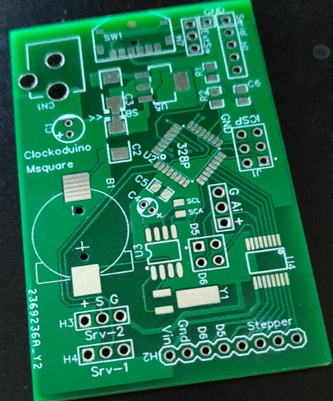
04/17/2020 at 06:00 • 0 commentsI have now designed a PCB which is meant to cover all my clocks, past and future.
![]()
It has an ATMEL328P chip (internal clock) and a RTC chip with crystal and battery backup, a stepper driver, 5V regulator (optional, solderbridge to bypass). and a 3way button on the edge for setting time. Last but not at least plenty of pin holes for connecting things, stepper, and/or 2 servo, 2 digital IO, one analog, Serial for programming or debugging and the standard ICSP.
For this clock, the Stepperdriver part will not be populated, and the barrel connector will use 5V and no regulator either.
Of course, I still have to solve the mechanical problems I have.
-
Completion attempt 2
01/19/2020 at 18:07 • 0 comments"Attempt 2", because Attempt 1 was finished last summer, and being exhibited in two German Makerfaires. But it was unreliable, so a bit of fudging was needed so it worked with the minut and hour hand at least.
It tells the time
Once one tediuosly has set the hands and time, it does work.
Improvements done
I have now tweaked and redesigned the mechanisms that holds the other gears in place, while one gear is being moved.
The software can now set the clock chip, via the Serial interface. It can also set where the hands are now, (ie how much catchup there has to be after power loss) Incidentally, the Serial interface is already full of debugging commands, that allow advance by one tooth, move to next hour and such like. The position of the servos is defined in EEPROM tables, these are adjusted this way, too. These are all for rebuild/maintenance only.
Still outstanding
Basically get rid of the Serial hookup to "start" the clock. Two points:
Some easy way to set the hand position. I have an idea or two how to do this with a single optical gate and some "encoder-like" addition in the gear wheels.
As an interim design a button or two will be added to manually position the hands at 12 o'clock after power outage (assuming the clock chip battery has kept time).
The button(s) will also set the chip time at some point (design details outstanding - the challenge is the "feedback" on what time you are setting)
Lastly, the weekday and day gears need to be exchanged for ones with integral toothcount to the step size to get all hands to be spot-on. (see earlier project notes)
-
Early notes
01/10/2020 at 18:39 • 0 commentsThis is retroactive notes, based on memory of this project
Here is an early test (april 2019) done with the gear changer. At that point I presumed a single axis could hold the gears, but there was too much play up/down so the later design holds the gears with a guide rail. (see Gallery)
Gear calculations
60 minutes, 24 hours, 12 months are all factors of 120. So all gears have 120 teeth, and for a minute 2 teeth is the increment, 5 teeth/hour, 10/month. For weekday it is 17.14 teeth and day is 3.75 teeth. The software works out the nearest tooth. All teeth have to be aligned for the gear shift to work, ie movement is by whole teeth steps. The 1.5° error in positioning a pointer is barely visible.
However by cheating with the gear module, I can make a gear with a few teeth more or less, and still have it mesh with the servo gear. This will be done RealSoonNow, using a 119 tooth gear on the weekday and 128 teeth n the day gear.
The day scale has no tick mark at 0 as there is no day 0, but there is a 00:00 as time, so esthetically I wanted to avoid placing day 1 there. Otherwise a 124 tooth gear would be used on the day gear. The 28/29/30/31 problem for days in a month. is not a problem as the advancment is under software control it can easily skip from, say, 28 to 1.