 engineerkid1
-
1Circuit Diagram


Connect all the components according to the circuit diagram (1st image) given above.
SPONSOR LINK - UTSource.net
I would recommend to first check all the connections and working on a breadboard.
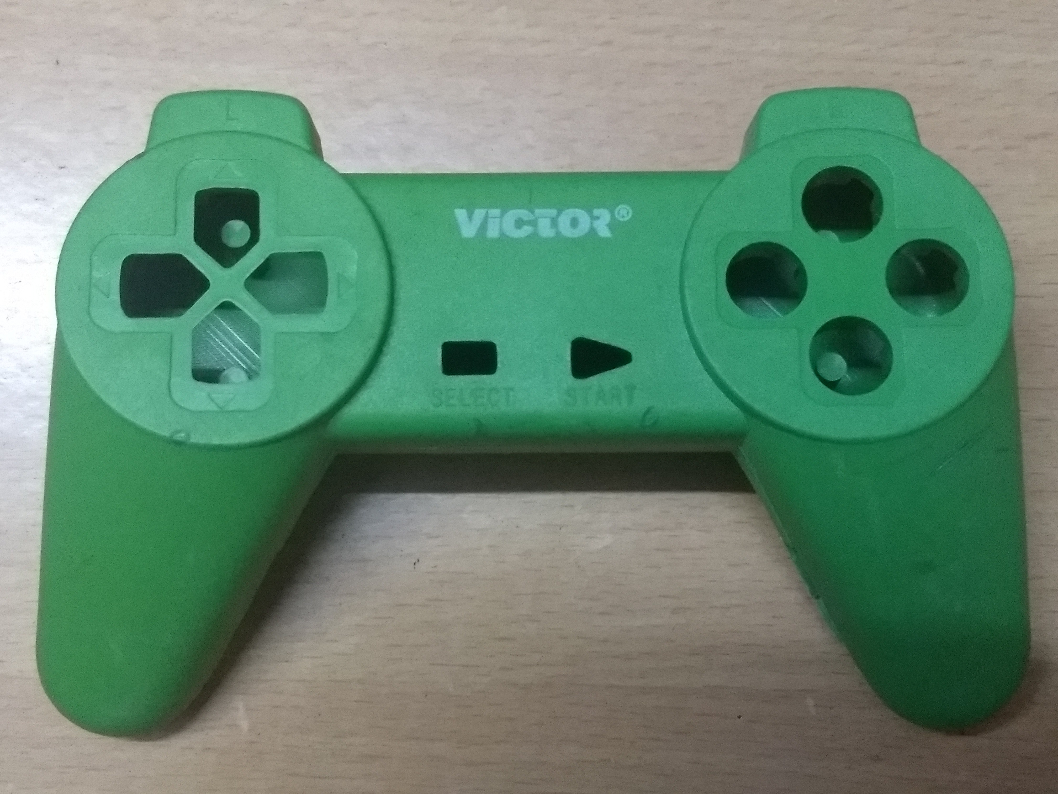
Key mapping :
The layout of my actual button placement is also shown above (2nd image) to give you a clear idea which button is positioned where, what label it is programmed with and what character it sends to the computer.
-
2Code for the Arduino
Now download the code and install the mouse.h and keyboard.h libraries. Upload the code to your Arduino.
You can copy the code from below.
#include<Mouse.h> #include <Keyboard.h> const int EMG = 2; //Emergency stop button :) const int L1 = 7; const int L2 = 8; const int P1 = 9; const int R1 = 14; const int R2 = 16; const int P2 = 10; const int D1 = 4; const int D2 = 5; const int D3 = 6; const int D4 = 3; const int SWITCH = 15; // digital pin 2 connected to SW output of JoyStick const int X_AX = A1; // analog pin 0 connected to X output of JoyStick const int Y_AX = A0; // analog pin 1 connected to Y output of JoyStick int range = 10; // output range or speed of X or Y movement int responseDelay = 5; // response delay of the mouse, in ms int threshold = range / 4; // resting threshold int center = range / 2; int EMGState = HIGH; int L1S = LOW; int L2S = LOW; int P1S = LOW; int R1S = LOW; int R2S = LOW; int P2S = LOW; int D1S = LOW; int D2S = LOW; //PREVIOUS STATES int D3S = LOW; int D4S = LOW; void setup() { pinMode(EMG, INPUT); pinMode(L1, INPUT); pinMode(L2, INPUT); pinMode(P1, INPUT); pinMode(D1, INPUT); pinMode(D2, INPUT); pinMode(D3, INPUT); pinMode(D4, INPUT); pinMode(R1, INPUT); pinMode(R2, INPUT); pinMode(P2, INPUT); pinMode(SWITCH, INPUT_PULLUP); Serial.begin(9600); Keyboard.begin(); Mouse.begin(); } void loop() { EMGState = digitalRead(EMG); if (EMGState == HIGH) { Serial.println("FAULT"); Keyboard.releaseAll(); Keyboard.end(); Mouse.end(); } else { //Serial.println("OK"); int L1STATE = digitalRead(L1); int L2STATE = digitalRead(L2); int P1STATE = digitalRead(P1); int D1STATE = digitalRead(D1); int D2STATE = digitalRead(D2); int D3STATE = digitalRead(D3); int D4STATE = digitalRead(D4); int R1STATE = digitalRead(R1); int R2STATE = digitalRead(R2); int P2STATE = digitalRead(P2); if(L1STATE==HIGH && L1S == LOW) { Serial.println("L1 PRESSED"); Keyboard.press('K'); //K } if(L1STATE==LOW && L1S == HIGH) { Serial.println("L1 RELEASED"); Keyboard.release('K'); //K } if(L2STATE==HIGH && L2S == LOW) { Serial.println("L2 PRESSED"); Keyboard.press('J'); //J } if(L2STATE==LOW && L2S == HIGH) { Serial.println("L2 RELEASED"); Keyboard.release('J'); //J } if(P1STATE==HIGH && P1S == LOW) { Serial.println("P1 PRESSED"); Keyboard.press('H'); //H } if(P1STATE==LOW && P1S == HIGH) { Serial.println("P1 RELEASED"); Keyboard.release('H'); //H } if(R1STATE==HIGH && R1S == LOW) { Serial.println("R1 PRESSED"); //L Keyboard.press('L'); } if(R1STATE==LOW && R1S == HIGH) { Serial.println("R1 RELEASED"); //L Keyboard.release('L'); } if(R2STATE==HIGH && R2S == LOW) { Serial.println("R2 PRESSED"); //G Keyboard.press('G'); } if(R2STATE==LOW && R2S == HIGH) { Serial.println("R2 RELEASED"); //G Keyboard.release('G'); } if(P2STATE==HIGH && P2S == LOW) { Serial.println("P2 PRESSED"); //F Keyboard.press('F'); } if(P2STATE==LOW && P2S == HIGH) { Serial.println("P2 RELEASED"); //F Keyboard.release('F'); } if(D1STATE==HIGH && D1S == LOW) { Serial.println("D1 PRESSED"); //W Keyboard.press('W'); } if(D1STATE==LOW && D1S == HIGH) { Serial.println("D1 RELEASED"); //W Keyboard.release('W'); } if(D2STATE==HIGH && D2S==LOW) { Serial.println("D2 PRESSED"); //A Keyboard.press('A'); } if(D2STATE==LOW && D2S==HIGH) { Serial.println("D2 RELEASED"); //A Keyboard.release('A'); } if(D3STATE==HIGH && D3S==LOW) { Serial.println("D3 PRESSED"); //S Keyboard.press('S'); } if(D3STATE==LOW && D3S==HIGH) { Serial.println("D3 RELEASED"); //S Keyboard.release('S'); } if(D4STATE==HIGH && D4S==LOW) { Serial.println("D4 PRESSED"); //D Keyboard.press('D'); } if(D4STATE==LOW && D4S==HIGH) { Serial.println("D4 RELEASED"); //D Keyboard.release('D'); } L1S = L1STATE; L2S = L2STATE; P1S = P1STATE; R1S = R1STATE; R2S = R2STATE; P2S = P2STATE; D1S = D1STATE; D2S = D2STATE; D3S = D3STATE; D4S = D4STATE; int xReading = readAxis(A1); int yReading = readAxis(A0); Mouse.move(xReading, yReading, 0); if (digitalRead(SWITCH) == LOW) { if (!Mouse.isPressed(MOUSE_LEFT)) { Mouse.press(MOUSE_LEFT); } } else { if (Mouse.isPressed(MOUSE_LEFT)) { Mouse.release(MOUSE_LEFT); } } delay(responseDelay); } } int readAxis(int thisAxis) { int reading = analogRead(thisAxis); reading = map(reading, 0, 1023, 0, range); int distance = reading - center; if (abs(distance) < threshold) { distance = 0; } return distance; } -
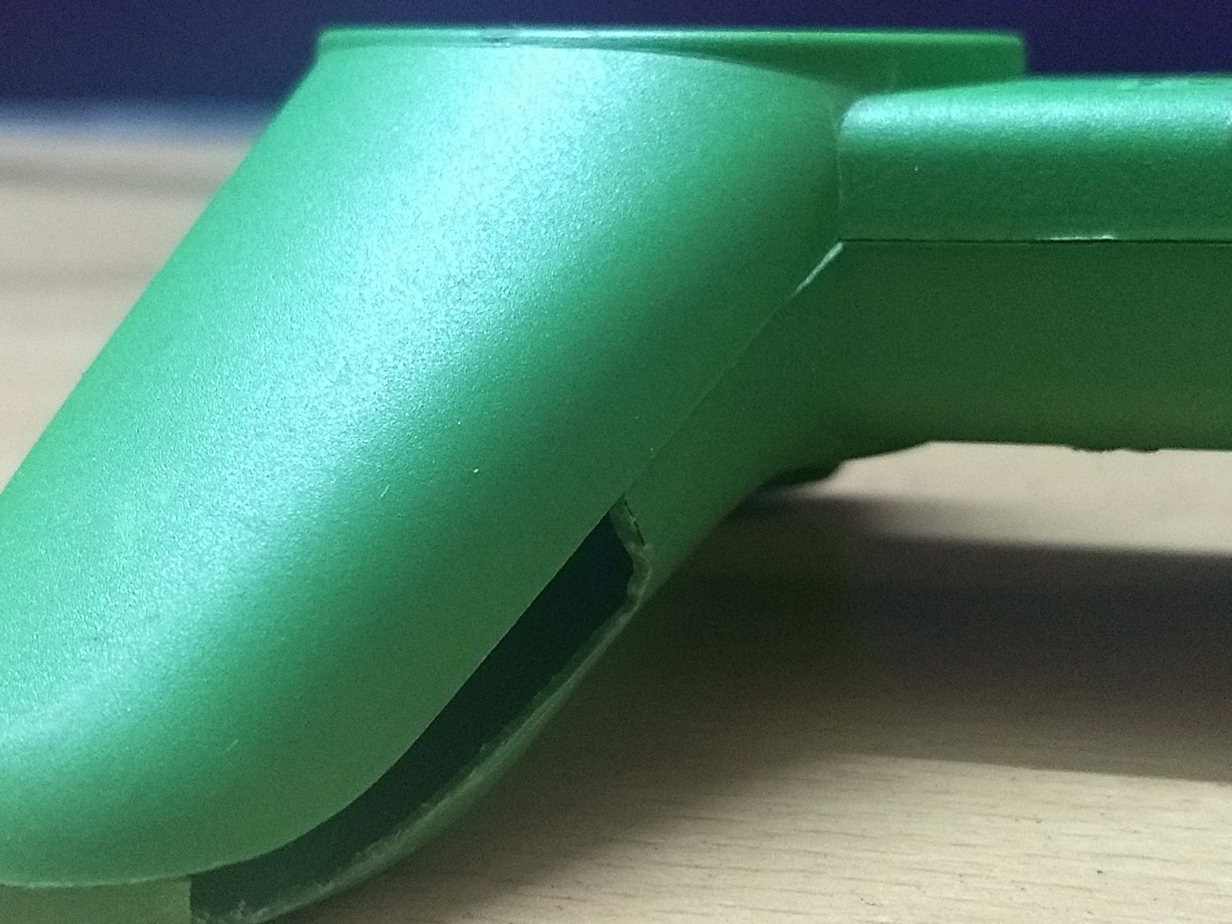
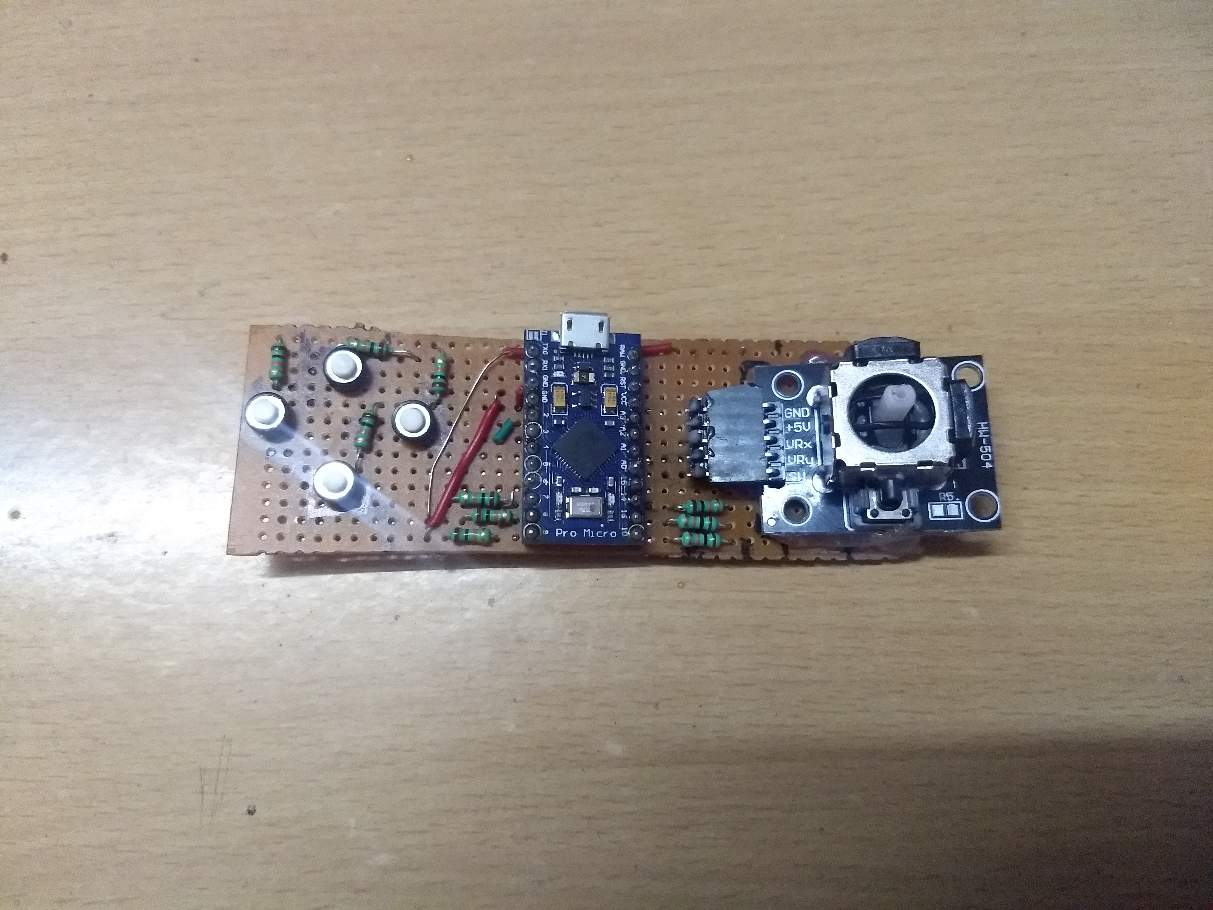
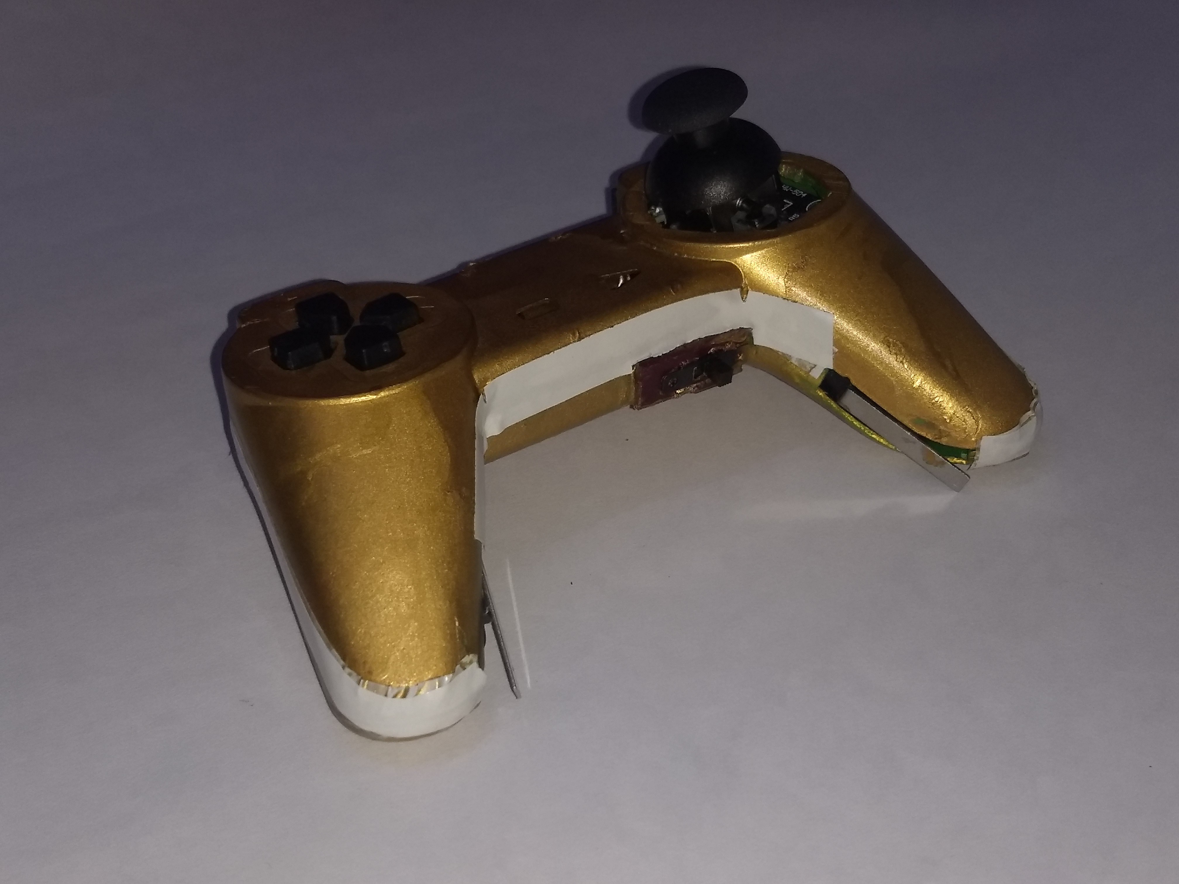
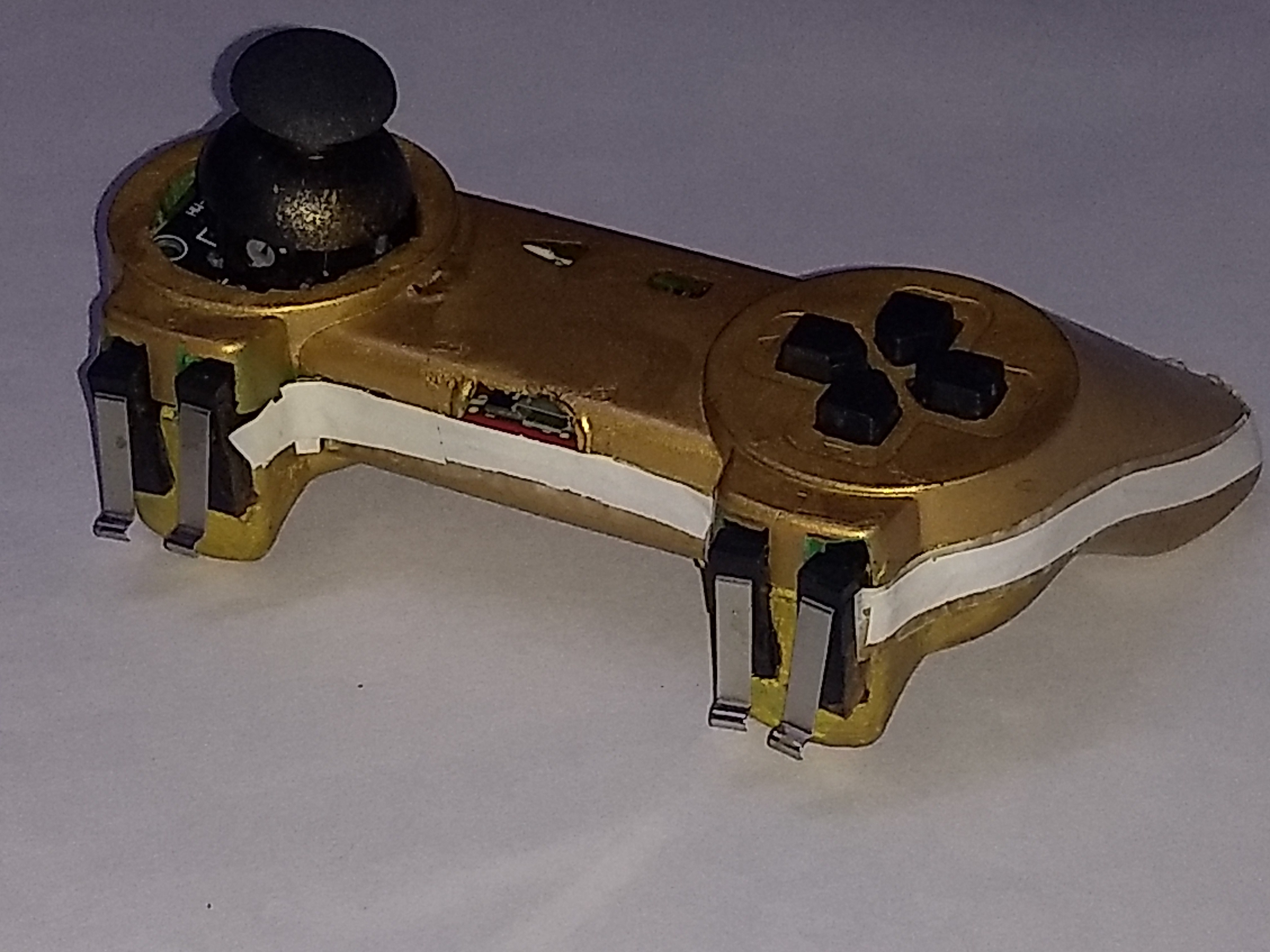
3Cutting, Painting and Soldering
First cut the PCB according to the size of the Game pad and align the push buttons and the joystick module. You can avoid this hectic task of soldering by ordering a PCB. UTSource.net provide quality PCB's at affordable rates.
Then paint the game pad with the color of your choice.
Now solder the push buttons and joystick on general purpose pcb.
Then fix the limit switches in their positions with the help of some super glue.
Solder the remaining components and do a final test.
I have attached images below for reference.
![]()
![]()
![]()
![]()
![]()
![]()
-
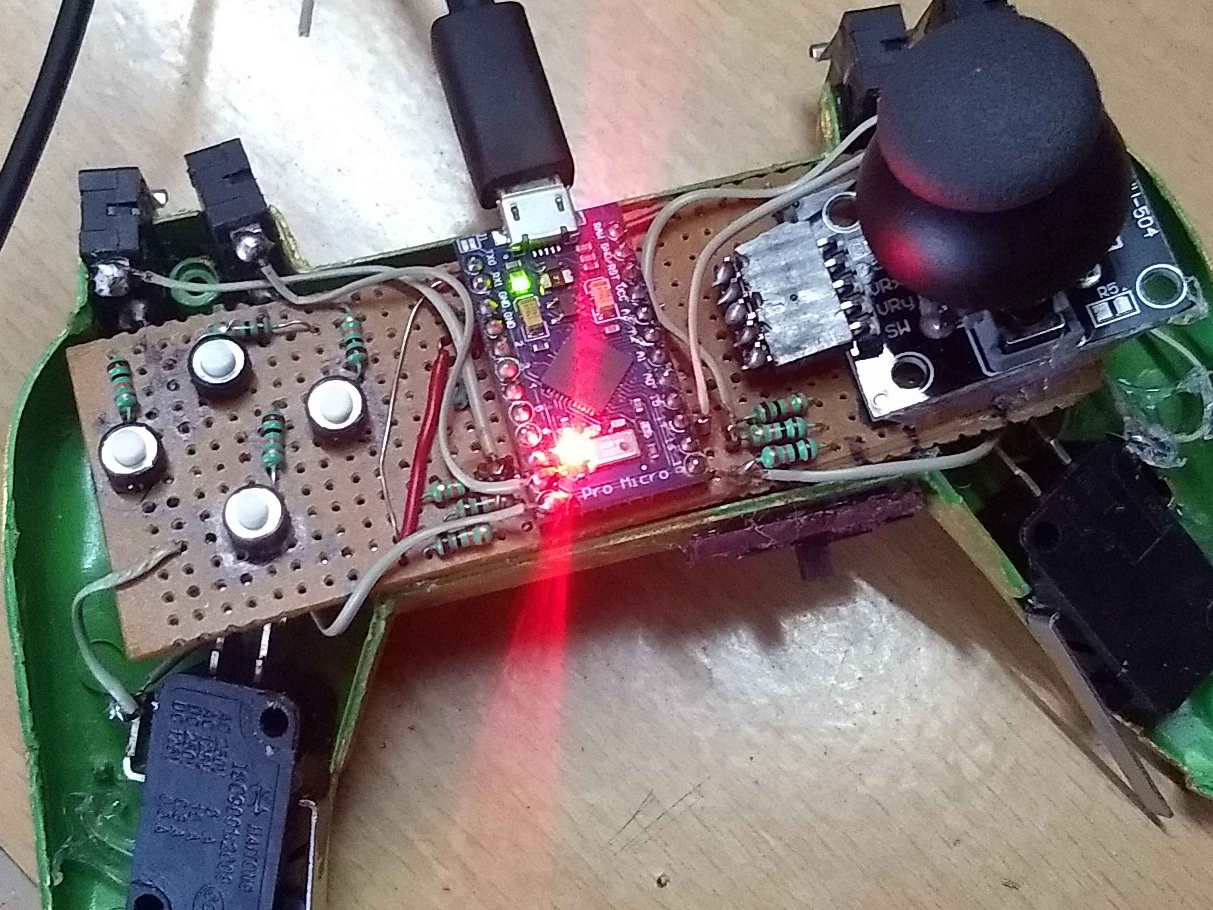
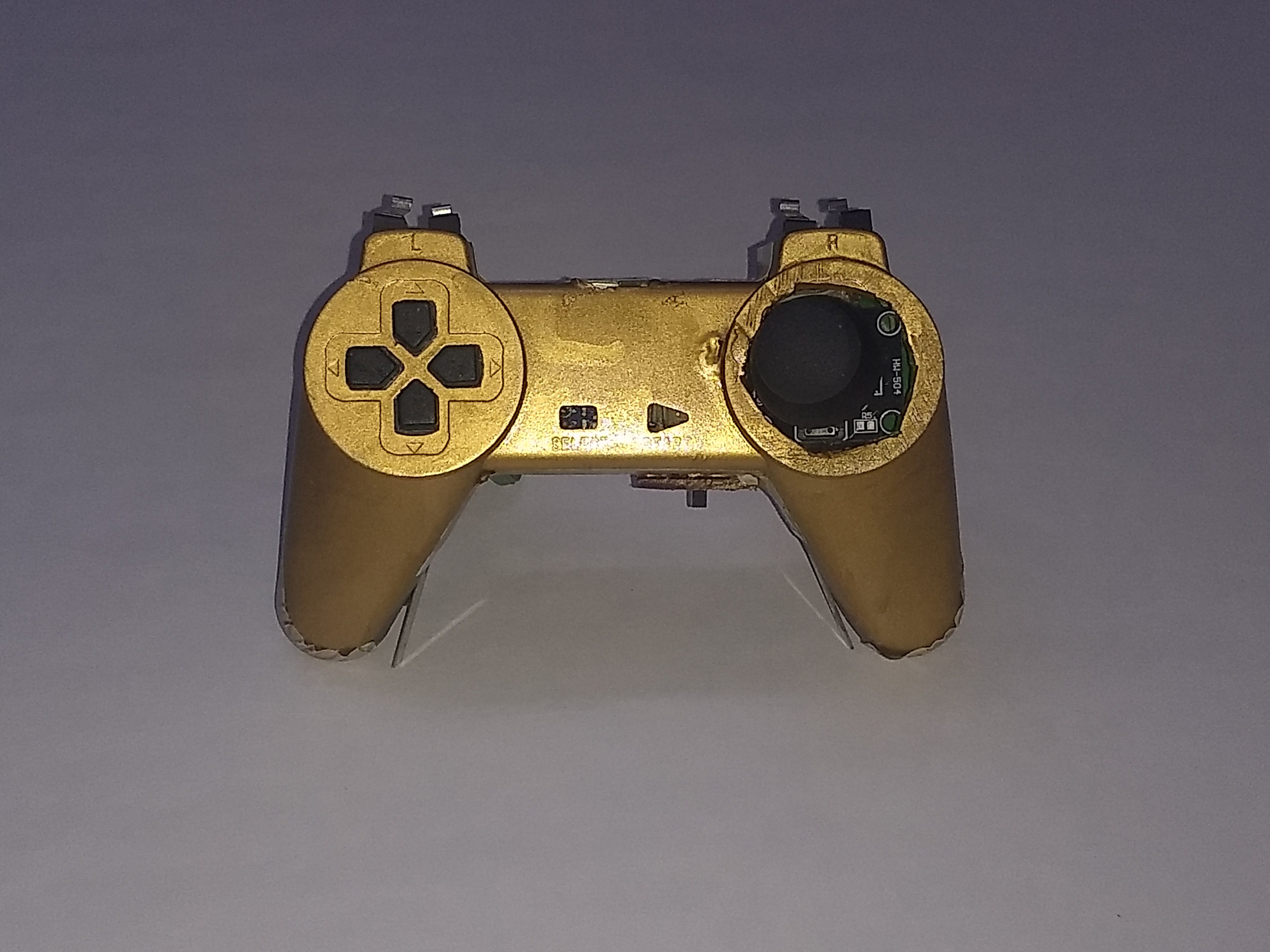
4Putting It All Together
Now close the enclosure with the help of some screws.
I have attached some pictures above to show you how the final product looks like.
That's it you are done. Now try playing some games. You can play emulator as well as PC games (which do not require more number of keys).
![]()
![]()
![]()
![]()
I know I have done a pretty bad job at painting. But the controller works fine. This is my first project on Hackaday and I hope this project helped you. Thank you.
ARDUINO CONTROLLED GAMEPAD FOR PC
In this project I converted an old gaming controller & made it compatible to play PC games.


Discussions
Become a Hackaday.io Member
Create an account to leave a comment. Already have an account? Log In.