-
Series Recap
06/03/2021 at 16:42 • 3 commentsIt's been over a year that I've been procrastinating working on this project. Rather than make any real progress I thought I'd show off some dead-end hardware.
Minitoy
![]()
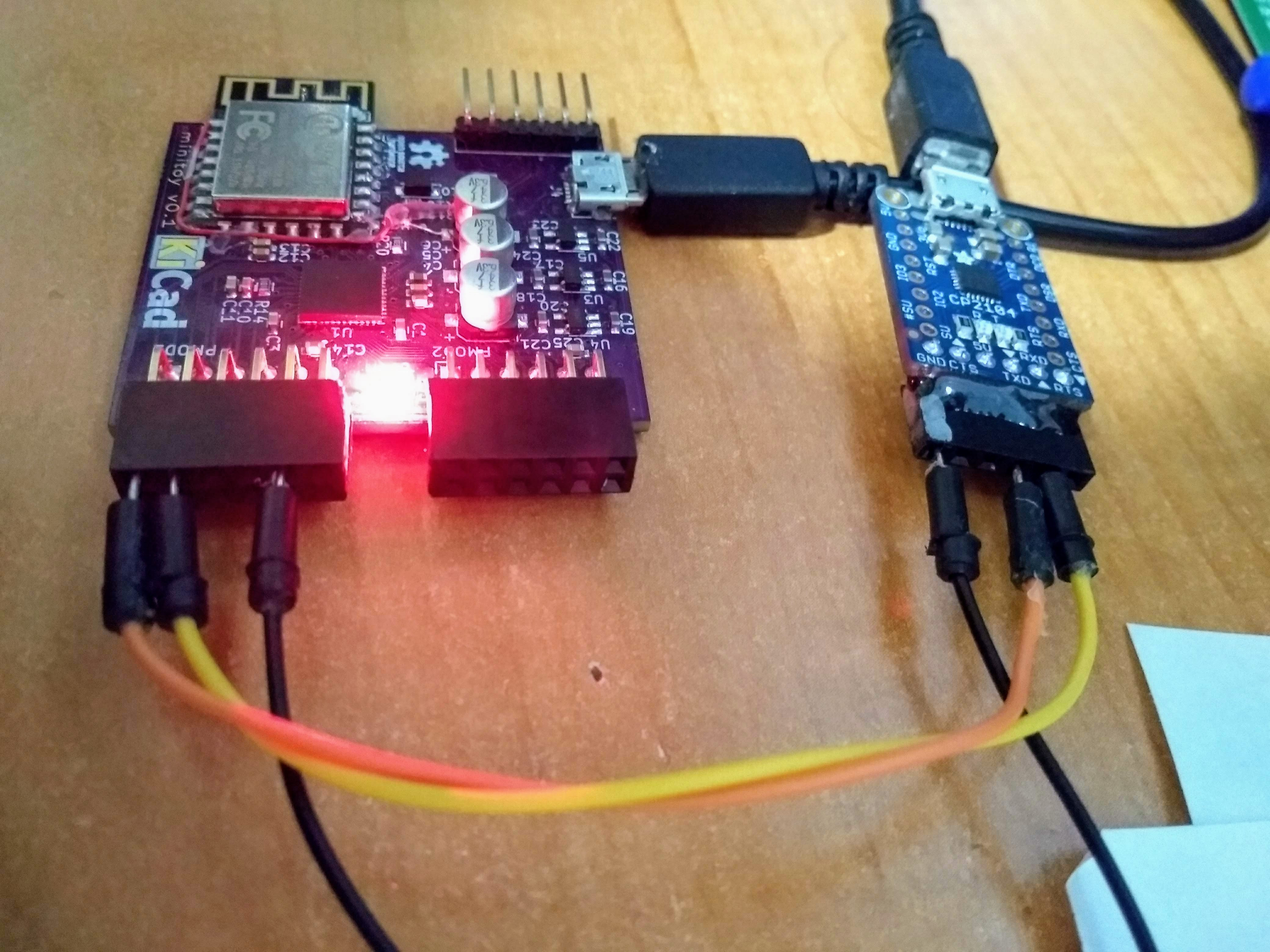
I created Minitoy during the great flood of Icestorm compatible boards of '18. All of the ICE40 FPGA boards were either disproportionately expensive, lacking in features I wanted, or vaporware, so I made my own. Minitoy has an ICE40UP5K bootstrapped by an ESP8266 running Micropython, which ended up being a testbed for the UP5K + ESP32 in Blinkencard. One feature I wanted was PMOD compatibility so I could use off-the-shelf FPGA I/O modules, so 16 FPGA I/Os are brought out to 2 PMOD headers.
Prior to building this board, I did a proof-of-concept of the bootloader scheme with an off-the-shelf ESP8266 board and an Upduino 1.0. The Upduino 1.0 is a basic ICE40UP5K board that has little more than the FPGA and flash, so it was easy to disable the flash and use SPI from the ESP board to load the FPGA directly.
However I got a few things wrong, hence the bodge wires and external USB-to-serial. I messed up the ESP8266 bootmode straps and reset circuit, necessitating the bodge wires. I also used the wrong footprint for the RGB LED and had to settle for individual red and green LEDs tacked on the board. Additionally the power supply section is needlessly complex and large, and ended up taking up half the board area.
Still, I was able to assemble one prototype and get it working well enough to use. I played around with the icicle RISC-V port, and got a port of the Apple I emulator working (and contributed an ICE40UP5K target). Shortly after I started a new and demanding job and shelved all my projects.
Blinkencard V1.0
About a year later, I got the itch again to do a personal project. A coworker had purchased a blue powder coated sheet metal enclosure for a project that never happened, and a water cooler conversation about what to do with it inevitably turned to making an Altair clone. We never did anything with that case, and it's still sitting on top of a storage cabinet.
But it did get me thinking about what made the Altair 8800 and the S100 hobbyist scene so appealing at the time. Certainly there's historical significance, and the visual and tactile experience of the LED and toggle switch front panel. Back in the day though, the idea of owning a computer that you made and can modify and extend to meet your own needs made them the popular precursor to the home computers of the late '70s and '80s. A bunch of projects over the last few years, namely RC2014, have tried to capture that sentiment using components that are still available and roughly period-correct. And while it would be easy and fun to throw money at a kit, I wanted to get deeper experience with FPGAs and use Verilog instead of chips and solder for that same sort of expandability.
So I made Blinkencard 1.0.
![]()
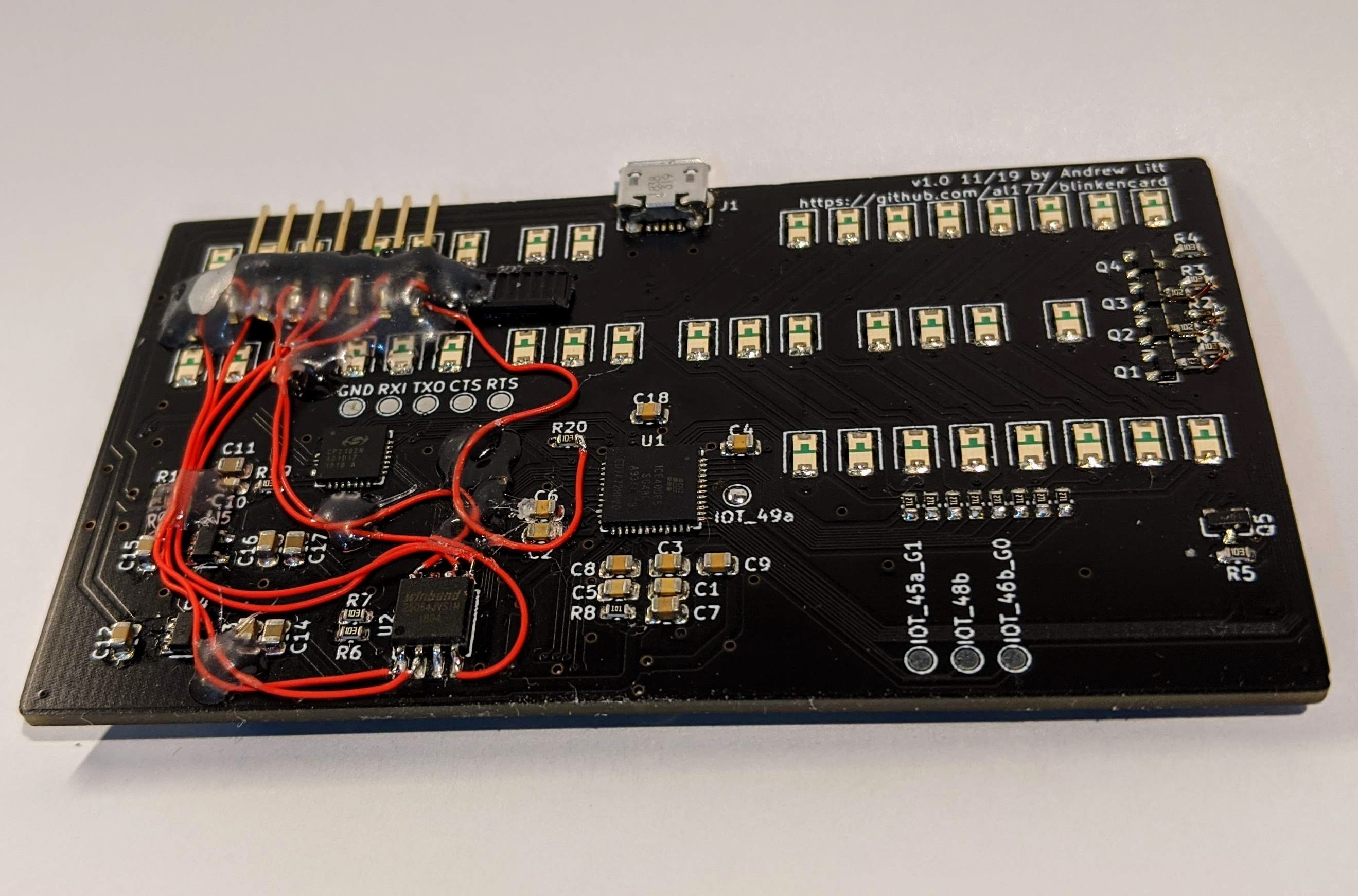
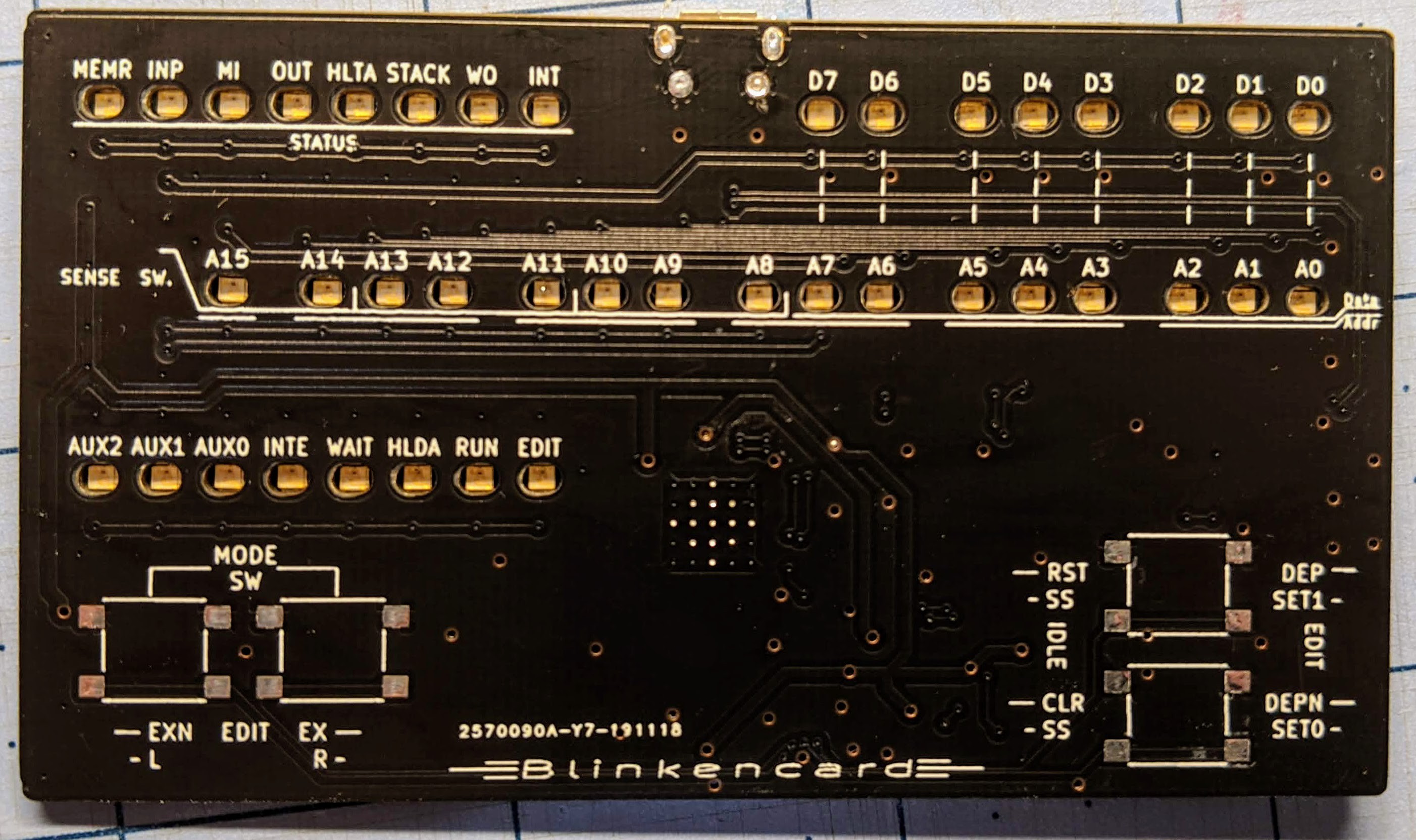
Originally I wanted to make it a business card to hand-out because it seemed like a thing that one does. I planned to use JLCPCB's assembly service since all those LEDs and discretes are a pain to solder. Everything in the design except the FPGA was in JLCPCB's library, leaving the FPGA which I could solder easily with hot air and paste. The front panel looks almost identical to the 2.0 design, and the primary mode of use would be through the front panel buttons and LEDs. My thought was that it could be like an early handheld video game, but instead of controlling an LED football you would control bits on the address and data buses.
The nest of bodge wires and the hot glued header are for programming the flash. I though I could use the SiLabs CP2102 USB-to-serial I added for communication with a PC to program the SPI flash, but the bitbang mode I thought it was capable of doesn't exist. The USB port is useful only for serial console, while the header and an FTDI module are used for programming the bitstream to SPI.
![]()
I was able to get the s100fpga project's Altair emulation bitstream working on Blinkencard 1.0, and added the LEDs as address and data bus monitors to that project. The obvious next step would have been to write the button UI control and make it self-sufficient.
Then I watched some Altair 8800 demo videos, and realized that the front panel switches weren't fun to use at all. As I sat through various people toggle in mere 40 byte programs over many minutes, I realized that the front panel as the primary UI would be boring and tedious. In practice it seems that most Altair users used the front panel to bootstrap some other I/O device, then would use a terminal for further interaction. The USB-to-serial converter on the board could provide a terminal interface through a PC, but I thought the tiny board looked sad at the end of a tether connected to a larger machine.
I also hadn't considered how I'd do storage and other I/O. If I wanted my emulation to have the real Altair experience, I'd want to boot Altair disks and tapes. I planned to use the extra flash not occupied by the bitstream for disk emulation with custom CP/M BIOS drivers, but my failed SPI to USB plans killed that idea.
The 2.0 redesign fixes these problems by using the Micropython ESP bootstrapping that I proved out on the Minitoy, an ESP32 that has an additional UART to serve as a terminal for the emulated Altair, and doing away with a USB-to-serial chip. With a WiFi module I could connect my phone or a laptop wirelessly over telnet for the console, and use Micropython's webrepl to copy files to the flash in the ESP32 module. To avoid the tethered look and make it fully portable, I added a LiPo battery connector and charge controller, and pushed the ESP32 programming path to a set of pogo pin pads that would be needed only for initial board configuration.
-
BASIC casual
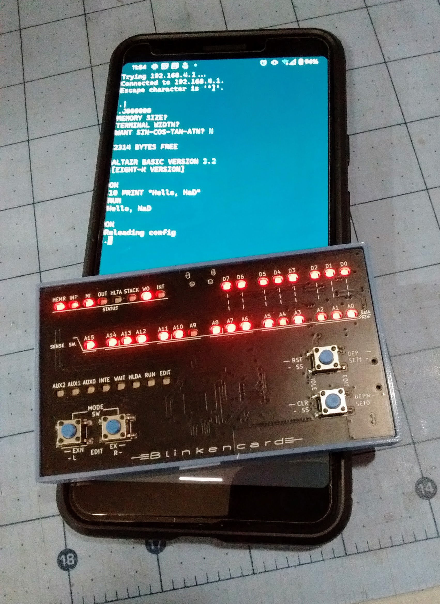
05/25/2021 at 17:08 • 0 commentsI haven't shown the Blinkencard doing its thing, so here's a console session over WiFi:
![]()
The initial '.' prompt is the Turnkey monitor - a CLI for peeking and poking at memory on Altair systems that don't have blinkenlights and switches. Here I'm running the BASIC ROM at address 0 (J000000) and entering a simple BASIC program.
The 'Reloading config' line comes from my telnet server which catches [CTRL-A] + R causing the ESP32 to reload the FPGA image and reset the emulation.
-
Blinkin' LEDs and killin' bits
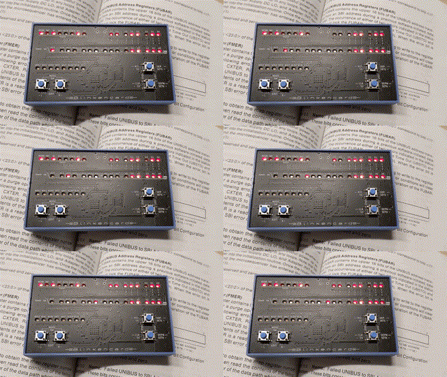
02/16/2020 at 22:55 • 0 commentsI've been working on this project off and on for about four months now. Someday I'll get to posting stuff about the architecture, project direction, blah blah. But for now, here's the Blinkencard running the once-popular killbits program, but without switches with which to kill the bits:
![]()
 ajlitt