DosFox
-
Schematics! Everybody needs good schematics
12/27/2019 at 01:38 • 1 commentI have often found that a good indicator on how well a project is documented is by the schematics. Are they easy to understand? Are they hand drawn? Produced by proper CAD software or MS paint?
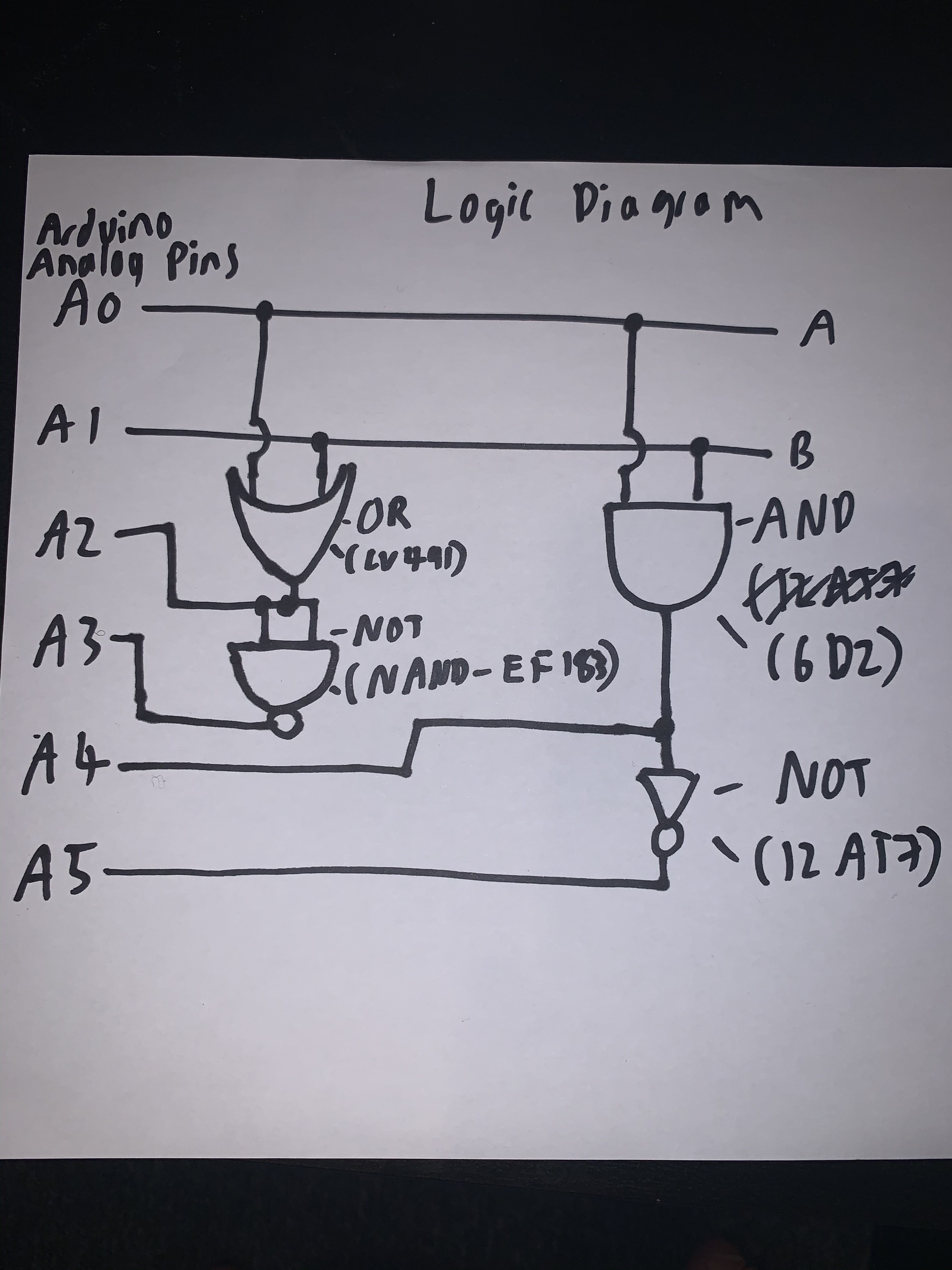
Basic Logic Diagram
![]()
So fundamentally, this is how the circuit works. Analog pins A0 and A1 are the inputs to the logic gates. To select a logic function, just read whichever pin is suitable.
A2 is the input coming from the OR gate, A3 is the input from the resulting NOR gate (inputs on a NAND shorted = NOT, which is inverting an OR gate = NOR), A4 is the AND gate input with A5 being the output from the NAND gate. Simples.
The schematics are mainly derived from this site:
https://www.ludd.ltu.se/~ragge/vtc/drawings/basic-blocks.html
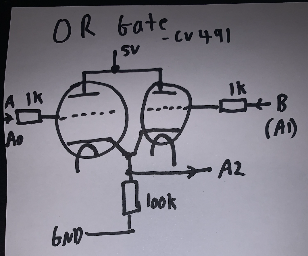
CV491 (Double Triode) OR Gate Schematic
This is identical to the higher voltage schematic, although it must be noted that the input voltage is only 5v, with the cathode resistor replaced by a 100k resistor.
Below my poorly drawn schematic versus the original can be seen.
![]()
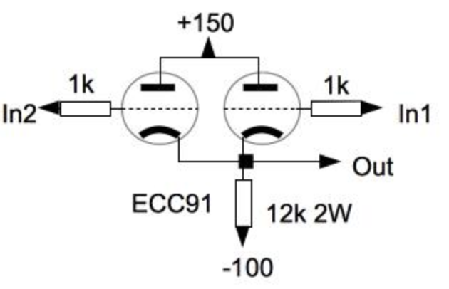
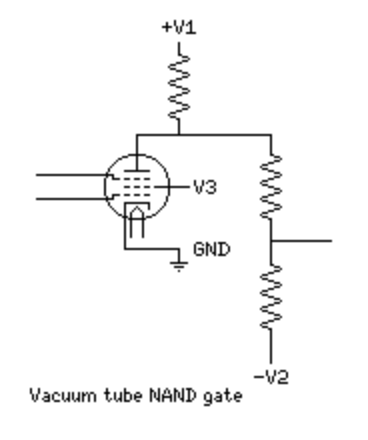
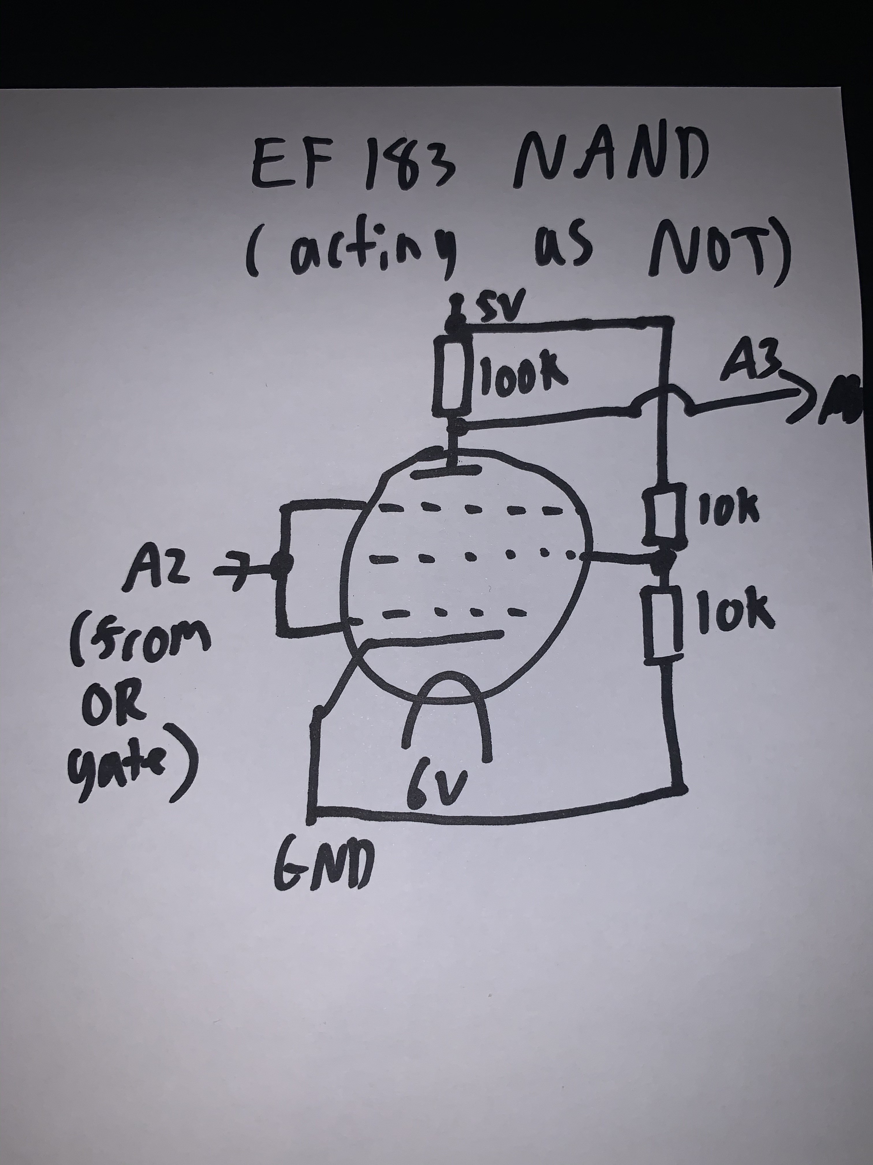
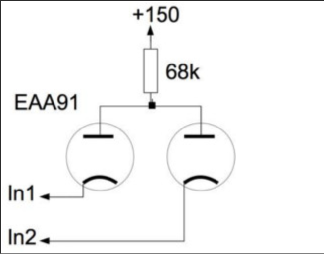
EF183 (Pentode) NAND Gate (acting as a NOR Gate)This was actually found elsewhere on the internet, mainly here:
https://www.diyaudio.com/forums/tubes-valves/86310-vacuum-tube-logic-gate.html
![]()
The usual changes were made when I converted this to my project.
V1 just became 5v, with a 100k resistor at the anode.
Additionally, as this was going to be fed into an arduino, the potential divider was removed, and the output is just fed straight into Analogue input A3.
V3 is supposedly half of V1 (not sure where I got that from), so this was produced by a potential divider formed of two 10K resistors to halve the input voltage.
Additionally the two inputs were tied together to produce a NOT gate, which in turn was connected to the output of the OR gate (effectively pin A2 on the arduino)
As with the OR gate, my fairly terrible schematic can be seen below:
![]()
It has been noted that the use of one of the control grids as an input is quite unusual, and that a friend of mine "has never seen that done before", admittedly this is my first project with Vacuum Tubes so I cannot really verify how usual or unusual this is.
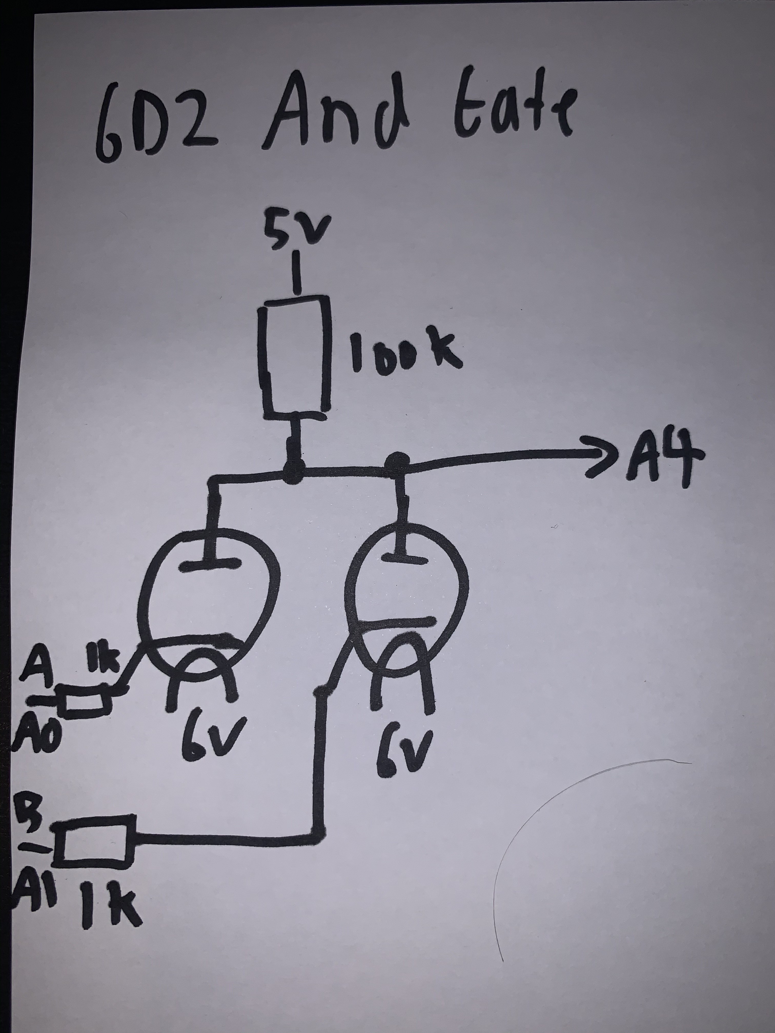
6D2 (Dual Diode) AND Gate
I must admit I am quite impressed (for some reason) that this actually works. It seems almost too simplistic to work. Then again a few people are quite impressed that the tubes are capable of producing any sort of logic with the voltages they are running at.
![]()
As with the other tubes, the anode resistor has been replaced with a 100K resistor and the input voltage is only 5v. However, a mistake is also present with the original schematic, as the output is not noted. Although this has been taken to be the voltage at the anode, which was passed to A4 on the arduino.
Again my dreadful schematic can also be seen below.
![]()
12AT7 (Dual Triode) NOT Gate
![]()
Ah finally! The final gate.
As can probably be guessed from the previous schematics, the 22K resistor was replaced for a 100K, and the tube was operating at 5V, not 150V... which would fry the arduino in an instant.
In a similar vein to the EF183 NAND gate shenanigans, the potential divider was removed in favour of just simply passing the resulting voltage to A5 on the arduino to work out later.
However, in contrast to the EF183 NAND gate, the inputs on the logic gate were not directly connected to the outputs of the previous gate, instead it is passed through a 1K resistor. This can be seen in my own schematics:
![]()
A Word on Heaters
As can probably be seen on my schematics (if you can decipher them that is) you can probably see that each of the heaters are being powered by 6v, whereas the Vout on the arduino Galileo is 12v, whereas some tube filaments can run at 12v but aren't? So whats going on?
The 6D2 and the EF183 both have filaments that run at 6v, however the CV491 and the 12AT7 have filaments that can run at 12v, but can be configured to run at 6v by connecting pins 4 and 5 to positive and pin 9 to ground.
To make my life simpler/easier for me to remember so I didn't accidentally burn out a few filaments, I configured all of the filaments for 6v. Then I was able to just easily connect two tubes in series so they would all happily glow from the 12v source. Luckily the Power Supply (And hence the Vin on the arduino header) provided with the Arduino Galileo is 12V.
-
Something About the Hitchhikers Guide and "middles"
12/26/2019 at 23:35 • 0 commentsOk Ok, so I am almost certain that the introduction was the most bland and disinteresting method of introducing a project *ever*, so hopefully I can rectify that.
The Middle
As the title may suggest, the project is happily at the middle of development. At the moment, the main electronics of the project have been completed, and a simple arduino sketch that cycles through 00, 01, 10, and 11 as well as monitoring the analog inputs to make sure all of the logic gates are behaving themselves. (trust me, at these voltages they do like to... not work as intended). The actual software still needing to be written. Theres a reason I'm a terrible electronics engineer, not a terrible software developer.
The current set up of the project is effectively a prototype - knocked together with tubes and resistors that I had on hand. I can at least say that I aim to produce a PCB version of this project (which still needs a catchy title) using only a single (CHEAP) tube that could be thrown onto tindie. Thats still in the future at least.
So what are the tubes, and the purpose of them?
CV491 - effectively a military 12AT7 (?), basically a dual triode, that is being used as an OR gate
EF183 - pentode, arranged as a NAND gate.. that has had its inputs shorted to a NOT gate, which inverts the output from the OR gate, so the output is a NOR gate (I did mention this was thrown together).
6D2 - dual diode, somehow SOMEHOW creates an AND gate, which is surprisingly effective.
12AT7 - another dual triode, only one of the triodes is used to create a NOT gate, inverting the AND output to produce a NAND gate. (the other triode in the tube didn't work as a NOT gate for some reason)
The vacuum tubes are soldered point to point (OK I am really struggling with the correct grammar there)
The resistors used for the anodes and the inputs are located on a separate piece of veroboard - makes connecting the arduino easier.
Low Voltage Vacuum Tube Logic Gates
Creating four basic logic gates (AND, OR, NAND, NOR) from common vacuum tubes, powered at low voltages