0%
0%
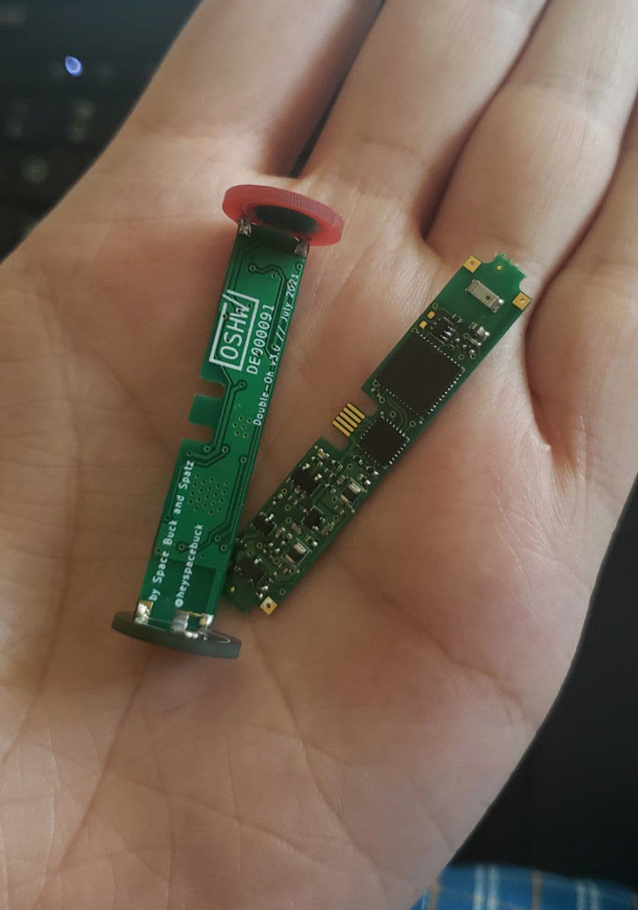
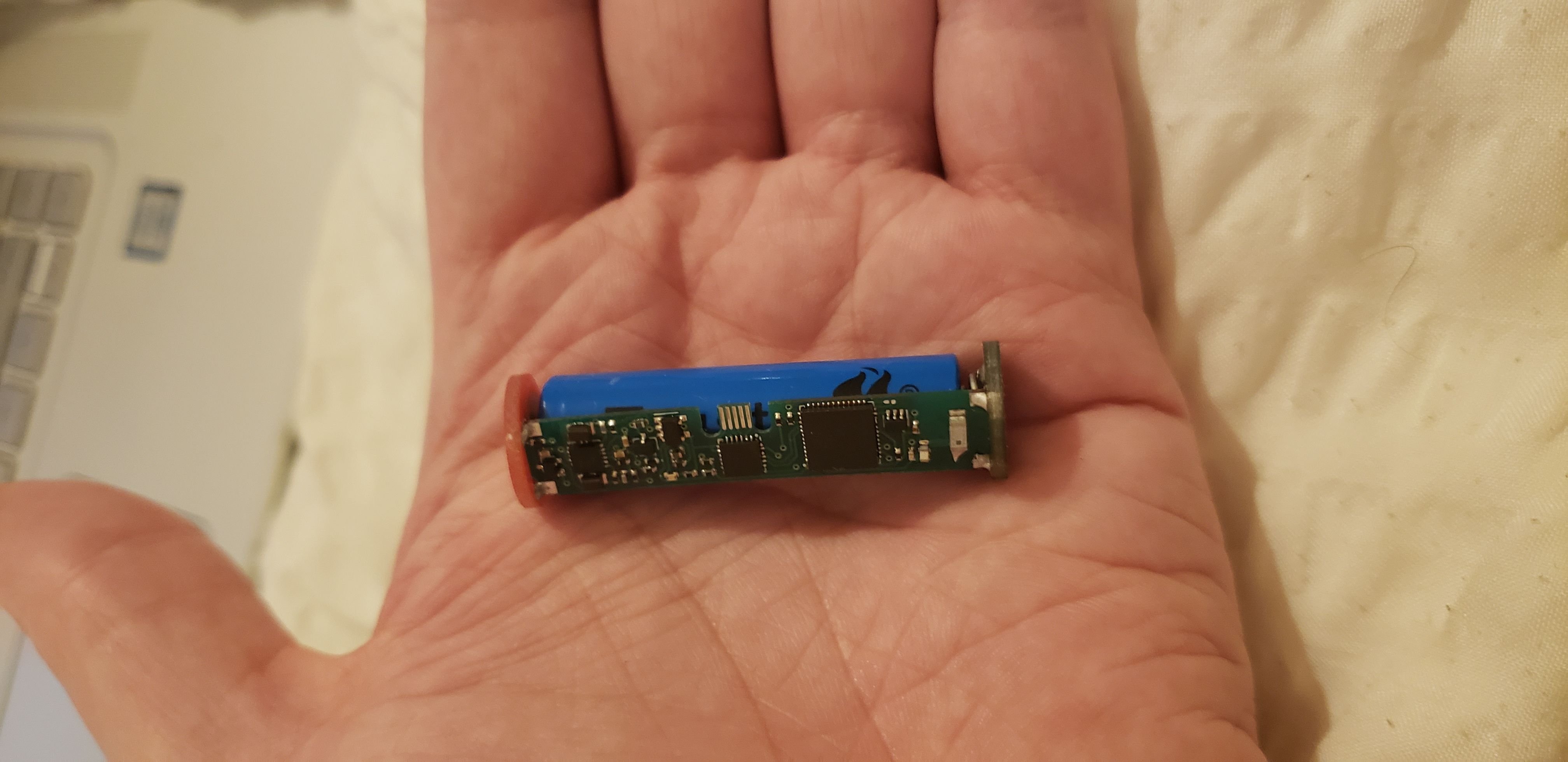
Double-Oh Battery
A Wi-Fi-enabled power supply in AA-battery form factor. Originally designed for sex toys but has the potential for so much more!
 Space Buck
Become a Hackaday.io member
Already have an account? Log in.
Just one more thing
To make the experience fit your profile, pick a username and tell us what interests you.
Pick an awesome username
hackaday.io/
Your profile's URL: hackaday.io/username. Max 25 alphanumeric characters.
Pick a few interests
Projects that share your interests
People that share your interests


 akupila
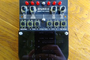
 Matt Bradshaw
 Derek F
 Matias N.
found your page from hackster.io article and watch the video. Sweet project. Love the idea. I doubt you can burn the motor by running them on 3.6V. Sure the lifespan of these motors will be shorter but due to the nature of the product don't think you run them 6h per day. Anyway you could easily block the on time when you boost voltage. Burst of 3.6V for 200ms and let motor cold down. Do you wrap the entire board into heatshrink?