fdufnews
-
Just a little update
07/30/2021 at 14:31 • 0 commentsCurrent state
I have added two new statements
PEEK(address) returns the content of memory cell at address
POKE(address, value) write value in memory cell at address
PEEK and POKE mainly help playing with the registers.
Added a scrolling buffer which ease displaying DIR and LIST screen by screen.
Work in progress
Currently, I am working on adding file manipulation inside BASIC programs.
I plan to add statements like open, read, write (binary and text)
-
You can save your program now
08/07/2020 at 20:04 • 1 commentI have just commited the updated software to my github.
The save/load/delete/dir functions are working like a charm. There is only one limitation no subdirectories allowed. I have made some tests with subdirectories but dir was always crashing. Regarding the application, I think it is of little importance.
I have adapted the already existing functions that were written for an external EEPROM
So:
SAVE "MYPROG.BAS, creates a file MYPROG.BAS containing a dump of the basic program space.
LOAD "MYPROG.BAS", loads the file MYPROG.BAS in memory and it can be executed
DIR, displays card content on the screen
DELETE "MYPROG.BAS", does what it means.
I have added two new functions
UNMOUNT, close the SD card and frees the memory in order to eject the card
MOUNT, open the card and keep it ready for use
MOUNT is automatic after a reset and when recovering from SLEEP
UNMOUNT is automatic before entering SLEEP
So the card can be extracted while the terminal is sleeping and the card recognized at wake up.
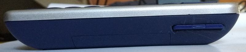
The status line has been slightly modified in order to display the status of the SD card.
The card reader is incorporated into the terminal.
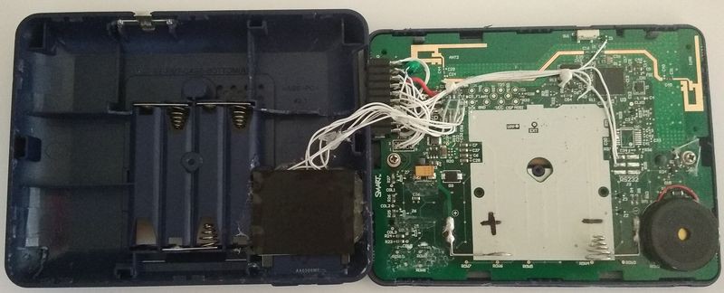
![]()
The inside of the terminal is now a big mess of wires
![]()
Edit: Made a little modification. As I want to add some statement to use data files I have added support for the extension to the filename. Now .BAS shall be added to save, load and delete.
-
The SD card finally wins the challenge
07/29/2020 at 12:06 • 0 commentsIt took long as I was balancing from one solution to the other.
The incorporated Flash was small and difficult to manage as it was needing a large buffer in RAM but it had the advantage of being already inside the terminal
On the other end the SD card was large enough to store many files, the block allocation and wear leveling was managed by the card itself but the terminal needed to be modified.
I finally choose the SD card. It has another advantage, the card can be extracted from the terminal and the files can be saved and edited on any computer which is great I think.
I have made some modification in the terrminal:
- desolder the Flash
- Connected a SD card reader
- Made some read/write tests
It works very well.
I am currently working on the software side implementing the SAVE and LOAD command. This commands are already implemented for an external I2C EEPROM. I am looking at keeping the same syntax to make the interface media independant.
The card reader is currently connected with flying wires. The next step will be mechanical modification in order to seamlessly integrate the reader on one side of the terminal.
-
Project is not dead
04/21/2020 at 06:26 • 0 commentsProject is not dead but I currently have no satisfying solution concerning the file system. Also, with COVID-19, I am confined at home and take that time doing some work on my house.
I have also considered replacing the flash inside the terminal with an SD card reader. It has some advantage the card handle the problem of allocating the blocks and the wear leveling, The SD card can also be extracted from the terminal and the files read or edited on any computer.
Apart from that, I have noticed that the standby mode is really efficient. My terminal is in stanby for months now (I think since mid of february) on a pack of NiMh batteries and I power it on from time to time to look at the battery level. The batteries are slowly draining out but the terminal is still functionnal.
To be continued......
-
Just a quick update
02/02/2020 at 18:23 • 0 commentsWell no great progress this time.
The main progress was on the status line. Previously there was a problem with the voltage of the battery now fixed with small modification in the initialization of the ADC.
The way status is managed has evolved. Previously, status was updated in the loop() function but the status line was not updated sometimes. I have moved the call to printStatus function in the functions that are reading the keyboard in host.cpp. In host_readLine, that is used for the command line and in host_ESCkeyPressed that is used during execution so now informations are also updated while the program is running. But in order to not slow down the software too much the status line is only updated every 2 seconds.
I have also corrected the function that compute BASIC memory usage. Previously, memory used by variables was not taken into account.
As usual, the code is on my github.
Next step will be saving and loading programs into the Flash memory of the terminal.
Edit: just found a bug in genbitmapRLE.py. The array size, in the generated file, was wrong, it was still the size of the bitmap not the one of the compressed file. The size of the firmware has suddenly lost 10kB.
-
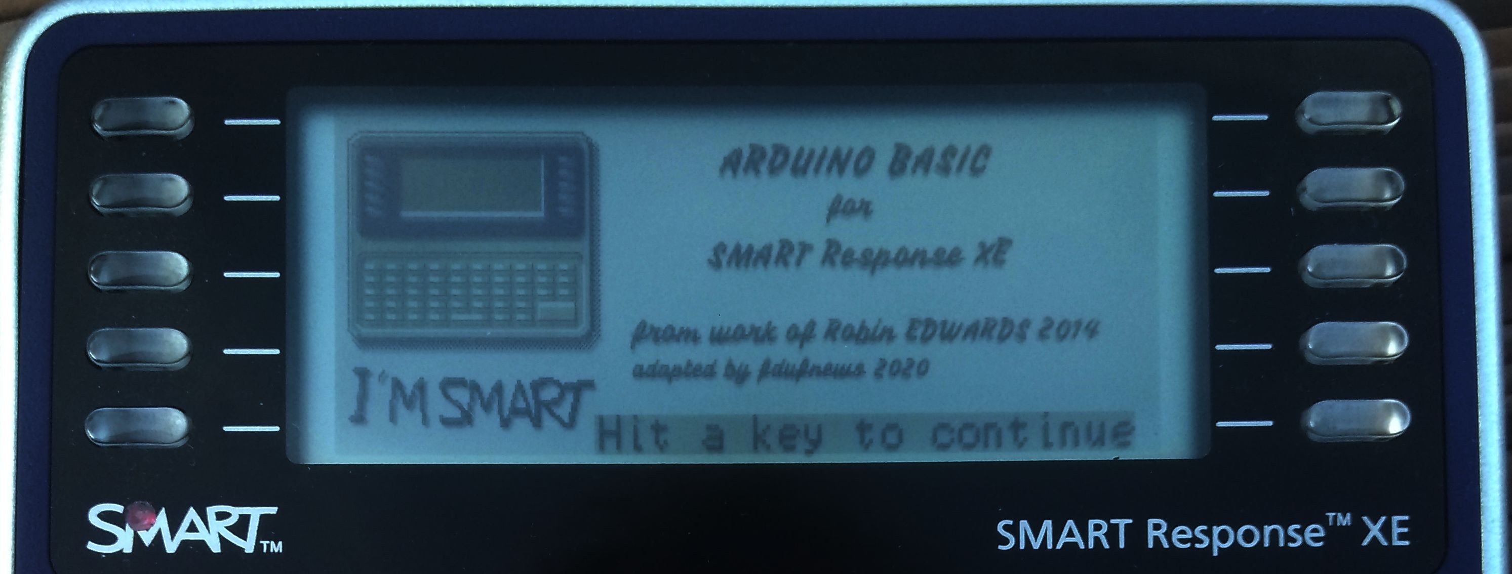
Story of a whim (and a splashscreen)
01/11/2020 at 22:27 • 0 commentsThe whim
When I received my terminals, I first powered them to see if they were operational. I liked the terminal startup screen and found it really attractive. There was a little picture of the terminal in level of gray.
So today I decided there was no reason why my terminal didn't have one.
The Problem
The problem is that a bitmap the size of the display is quite a large amount of bytes.
I first reproduced the bitmap of the original startup screen with GIMP. And, of course, found the file really large.
To simplify the software in the Arduino the picture was coded 3 pixels in a byte as the display expected it. The file was still large.
The solution
The second step was to find a way to compress the file in a way that allows it to be displayed with the limited power of the Arduino while significantly reducing the size of the file. For this I decided to choose an RLE compression. This type of compression is easy to program and it does not require a large buffer because decompression can be performed on the fly. To simplify data handling, the length of a run was limited to 254 bytes so the length can be stored on a single byte.
The file is a succession of bytes coding the size and the value each on a byte.
In order for the software to handle any size of picture, the width and the height of the picture are added at the beginning of the file.
// Original file LogoSMART2.data

#include <avr/pgmspace.h>

const uint8_t bitmap_logo2_rle[384/3*136+4+1] PROGMEM ={
    0x80, 0x01, // image width=384
    0x88, 0x00, // image height=136
    0X82,0x00,0X23,0xff,0X5C,0x00,0X01,0x1f,0X22,0x00,0X01,0x03,0X01,0xe0,0X5B,0x00,
    0X01,0xe0,0X01,0x09,0X21,0x49,0X01,0x40,0X01,0x1f,0X5A,0x00,0X01,0x1f,0X01,0x01,

.....
    0XFE,0x00,0XFE,0x00,0XF3,0x00,0X00,0x00
};
As a remainder, the name of the original picture is inserted as a comment in the header
The array is named bitmap_+<name of the output file>.
The first four bytes of the array are the size of the picture
Following are pairs of size, value, size, value as explained before.
The file ends with a pair of 00.
The tools
I have written a short python script to convert a picture in RAW format into a .h file that can be compiled with the software.
Here are the steps to generate the file:
- Create the picture with GIMP using only 4 colors
- Convert it to indexed palette
- Export to RAW (.data). Two files are generated image.data, image.data.pal (the second is of no use, it can be discarded)
- Using the python script a image.h file is generated
The syntaxe of the script is:
python genbitmapRLE.py <image.data> <image.h> <width> <height>
image.data : name of the picture in RAW format
image.h : name of the generated .h file
width : width of the picture (see note)
height : height of the picture (see note)
Note : as RAW files does not contain any information on the geometry of the picture it is necessary to add it by hand.
The result
The source picture is 384 x 136 pixels in 4 level of gray.
After encoding in "display format" the file is 384 x 136 / 3 = 17408 bytes large
After RLE compression the file is 7164 bytes large. This is still quite a large number of data but the ATmega128RFA1 has 128kB of flash so there is currently no problem.
![]()
This solution is quite efficient. The full screen picture is displayed in a fraction of a second (I have not made any measure, maybe I will do it one day)
-
First modifications to BASIC
01/06/2020 at 16:03 • 0 commentsAdapting Arduino BASIC to the SMART Response XE terminal was quite easy as the interface was limited to a pair of functions that were easy to replace with the ones in the Low Level Library.
But the display is not that large and the limitation imposed by its graphic controler lead to some problems. The contraint is that font width shall be multiple of 3. You can have small fonts that give many lines with many characters difficult to read (for my eyes at least) or large fonts that are easy to read but with less lines with less characters. It made me want to be able to change the font at any moment.. The low level library alreay defines 4 fonts
FontnameFontsize# of charper line# of linesper frameComment NORMAL 9 x 8 42 17 fill screen SMALL 6 x64 17 fill screen MEDIUM 12 x 16 32 8 8 unused lines LARGE 15 x 16 25 8 8 unused lines As the larger fonts leave 8 lines I decided to do the same for the smaller ones. The 8 unused lines will be used to display some information on screen.
The cpp file in which the interface with the host is defined was upgraded in order to be able to change the font on the fly. I first defined a structure that holds parameters depending on the font size. And replaced all the constants with members of the structure.
The terminal has some "special" keys. I used the menu one to launch a function with which I can change the font.
The 8 unused lines are located at the bottom of the screen. They display the status of the terminal. Actually, battery level, font used and memory usage.
-
Terminal modifications
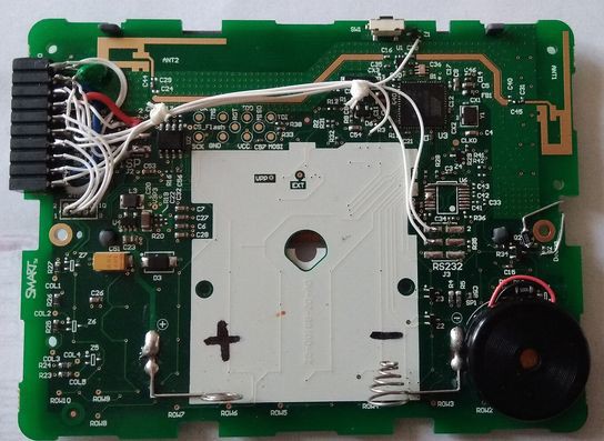
01/05/2020 at 09:43 • 0 commentsIn order to have a little more interaction with the terminal, I used provisions that had been planned in the terminal by the designers.
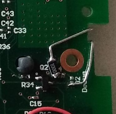
- adding a piezo speaker, the designers have made provision for a piezo speaker in the terminal. There is room for some resistors, a transistor and a piezo speaker
- adding an LED, there is also room for an LED and an optional transistor.
These modifications are described on my github in the hack directory
Concerning the BASIC language, there is already support for note generation and BASIC gives access to the I/O with the PIN statement. You can easily make your BASIC programs blink and beep as you wish.
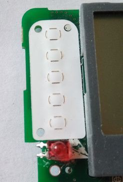
The LED is located on the top side so it can be seen from the front face and its legs are folded back in order to connect to the pads on the components side
![]()
![]()
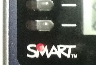
The front face is drilled but the hole does not open on the front face. The black coating of the film that makes the front face is scratch from the inside so the LED can be viewed. By doing so you don't have to perfectly align the LED position with the front hole.
![]()
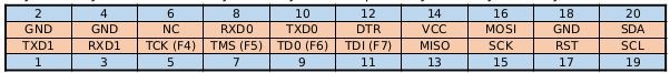
I have also added an extension connector in order to have access to some signals
![]()
The left part of the top row is compliant with the FTDI download cable pinout.
![]()
-
The starting point
01/04/2020 at 16:39 • 0 commentsSome words on the hardware used
The SMART Response XE terminal was designed years ago as an interactive terminal used in colleges. It is now a bit obsolete and can be purchased on Ebay for a tenth of its original price. For a few dollars you have a keyboard, a screen, and a ATmega128RFA1 processeur (an ATmega128 with wireless interface). The processor has 128kB of program Flash, 16kB of RAM and 4kB of EEPROM. The terminal integrates also a serial Flash that can be used too. As it is an ATmega, with minimum work, the software can be designed in the Arduino IDE giving access to all the existing softwares and libraries that were developed in the Arduino ecosystem.
I have bought 2 terminals and opened one to reverse engineer the schematic with the help of some hires pictures found here.
Some words on the softwares I rely on
The library I use is based on bitbank2 work. He has made a library that handles all the low level of the SMART Response XE Terminal. It manage the keyboard, the display. Some word on the display. It is probably the weakest link in this system, it has a good resolution but two drawbacks.
- pixels are written three at a time
- it is not possible to read back the frame memory
These two limitations prevent from making elaborate drawing as when setting a pixel you can modify two others.
These limitations are the reason why I will first work on text interface only for the BASIC.
The BASIC I will use is based on Robin Hedwards work. He has made an Arduino BASIC that works well and it needs not too much adaptation to work with the terminal.
SMART Response XE BASIC
Turn a SMART Response XE terminal into an 80's flavour pocket computer