Ahron Wayne
-
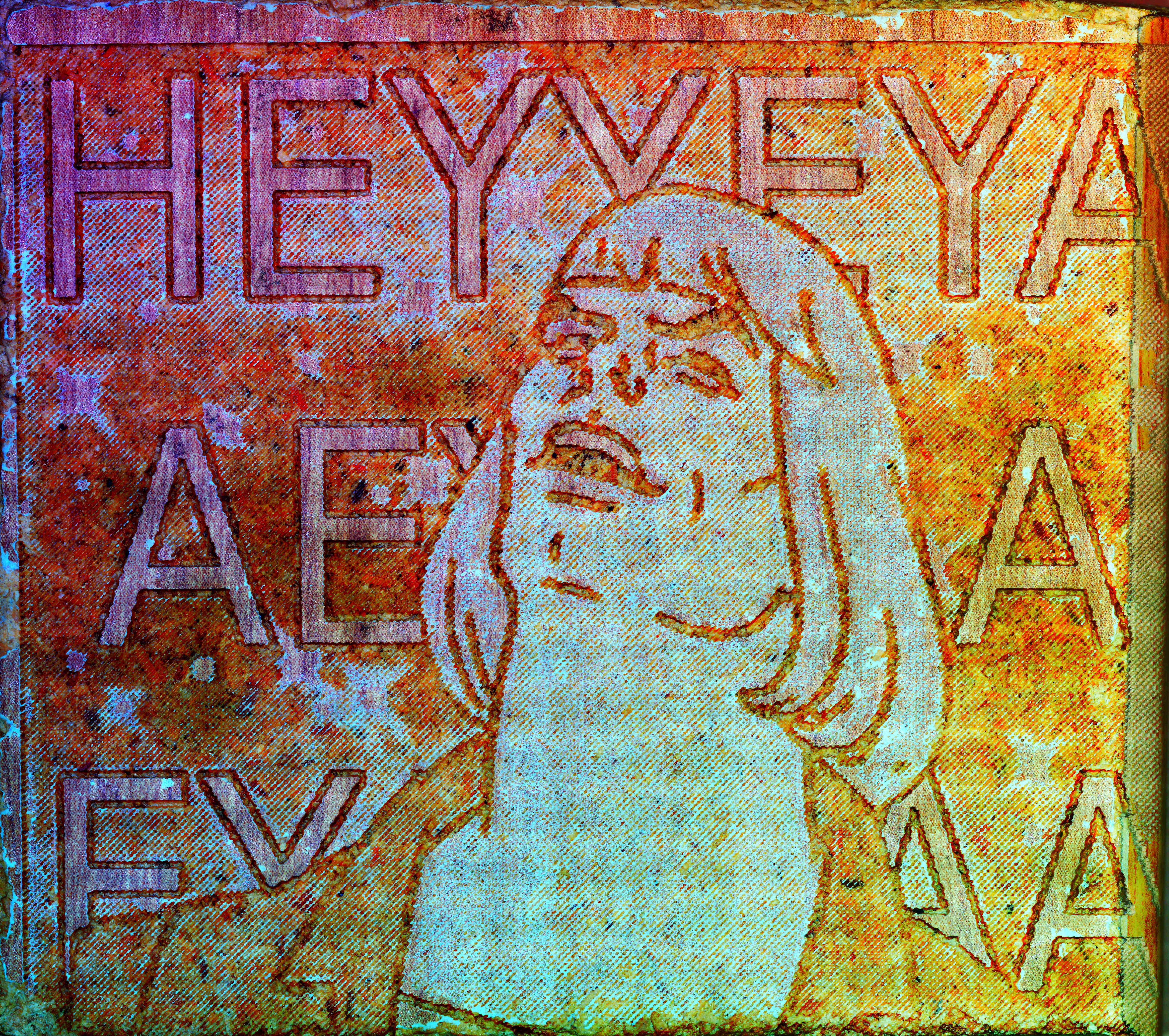
HEYAYAYAEEYAEYAY
02/29/2020 at 23:39 • 0 comments![]()
-
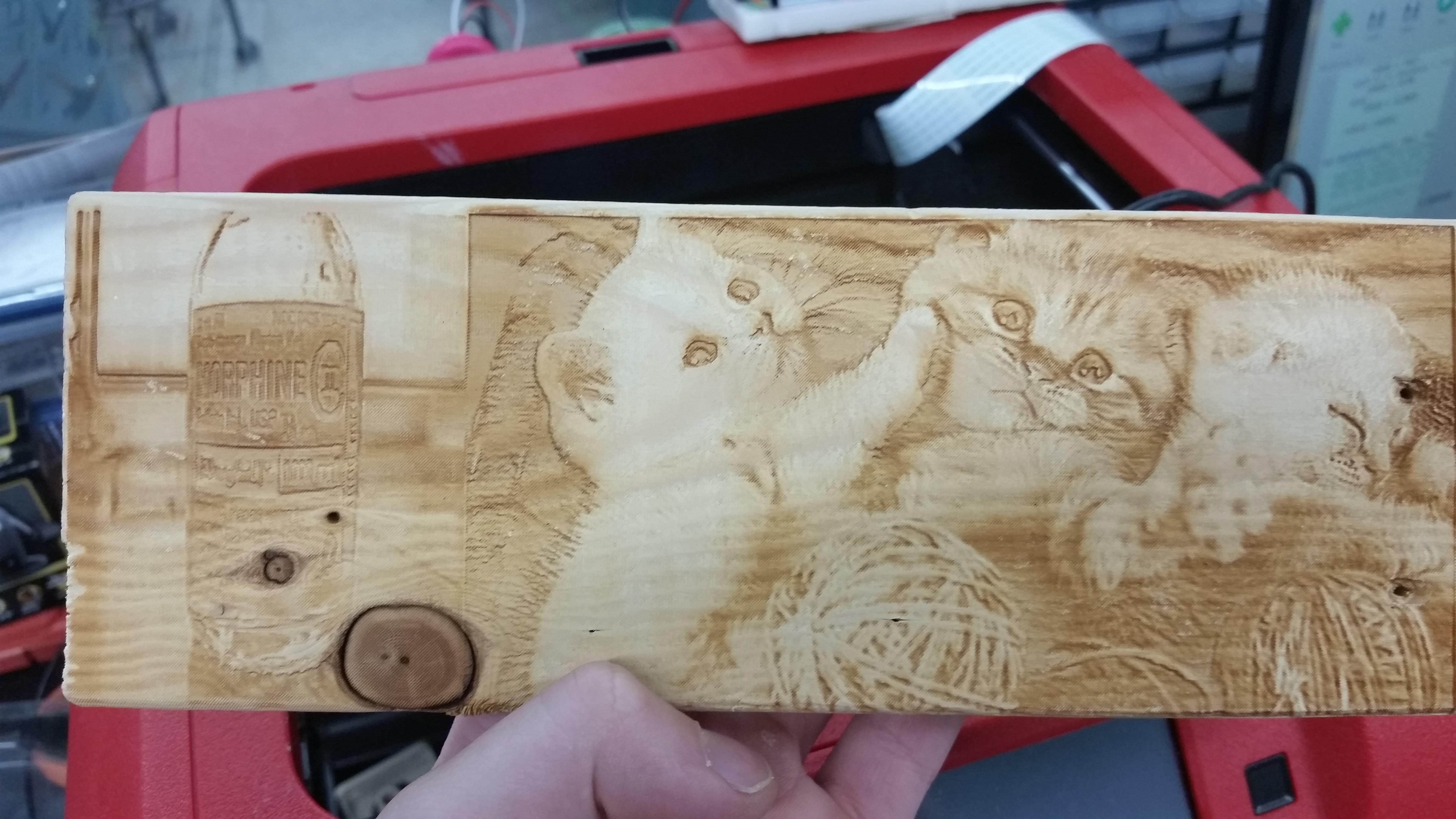
100 followers special: Laser engraved wood kittens
02/28/2020 at 00:08 • 0 commentsI made this for my mom a couple of years ago when she was sick. They're a few of her favorite things; kittens most of the time, morphine just while in the hospital.
![]()
So I stuck it on the Finder bed with some brown paper underneath and set it to take 350 pics with about 25 percent overlap (final 50 megapixels).
![]()
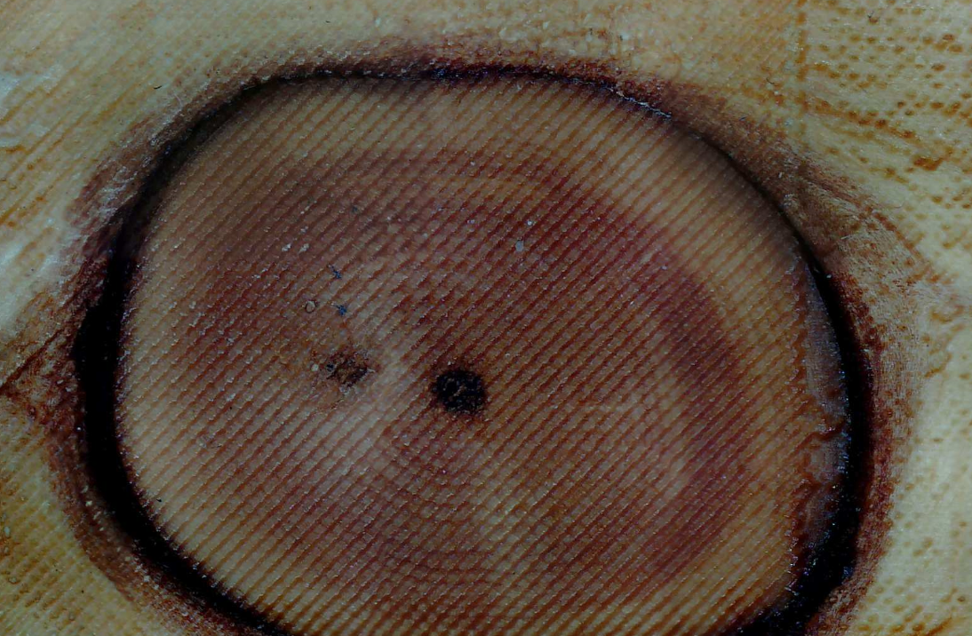
there're those obvious scan lines (from insufficient overlap over reflective areas), and I didn't show you the cropped part, but overall this one turned out awesome! I especially like looking at the areas where the grain of the wood is exposed:
You can clearly see both the rings and the individual raster dots from the laser. I might try doing a high res scan on this kind of feature next time.
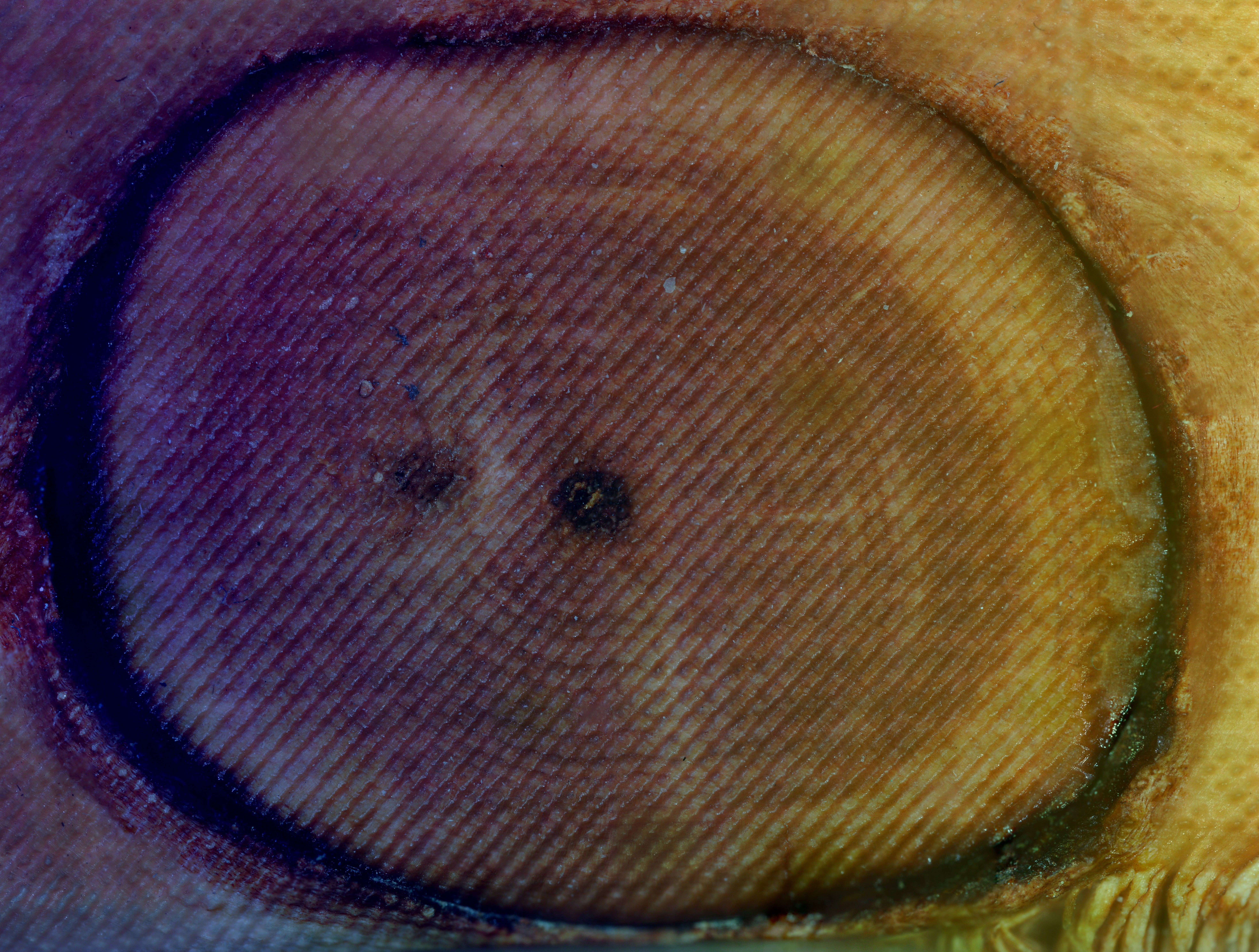
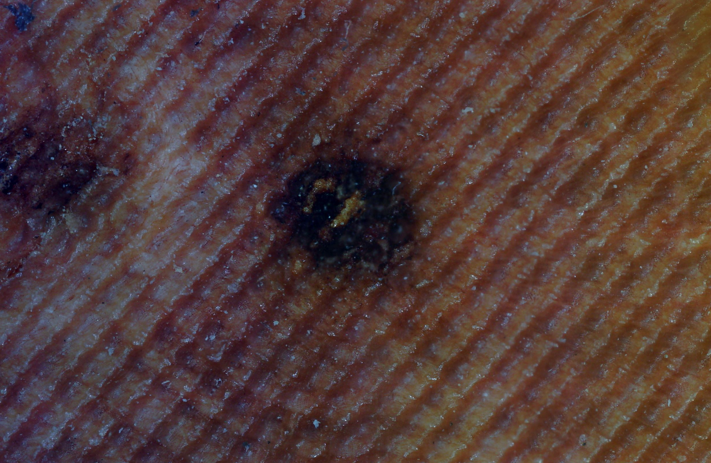
And now it's next time, so there it is:
![]()
484 pics of 40% overlap picked from 2 different Z heights (900 something total). Here is where you can clearly see the color artifacts from the stitcher, especially compared to the medium res image before it. as usual all the detail is still there, ICE is just weird about it.
And for the lazy who don't want to click, here's another zoom of the center of that image above:
Even that image displayed on most screens is a bit zoomable. I really want to go one level deeper, but I think I'd need some new equipment.
-
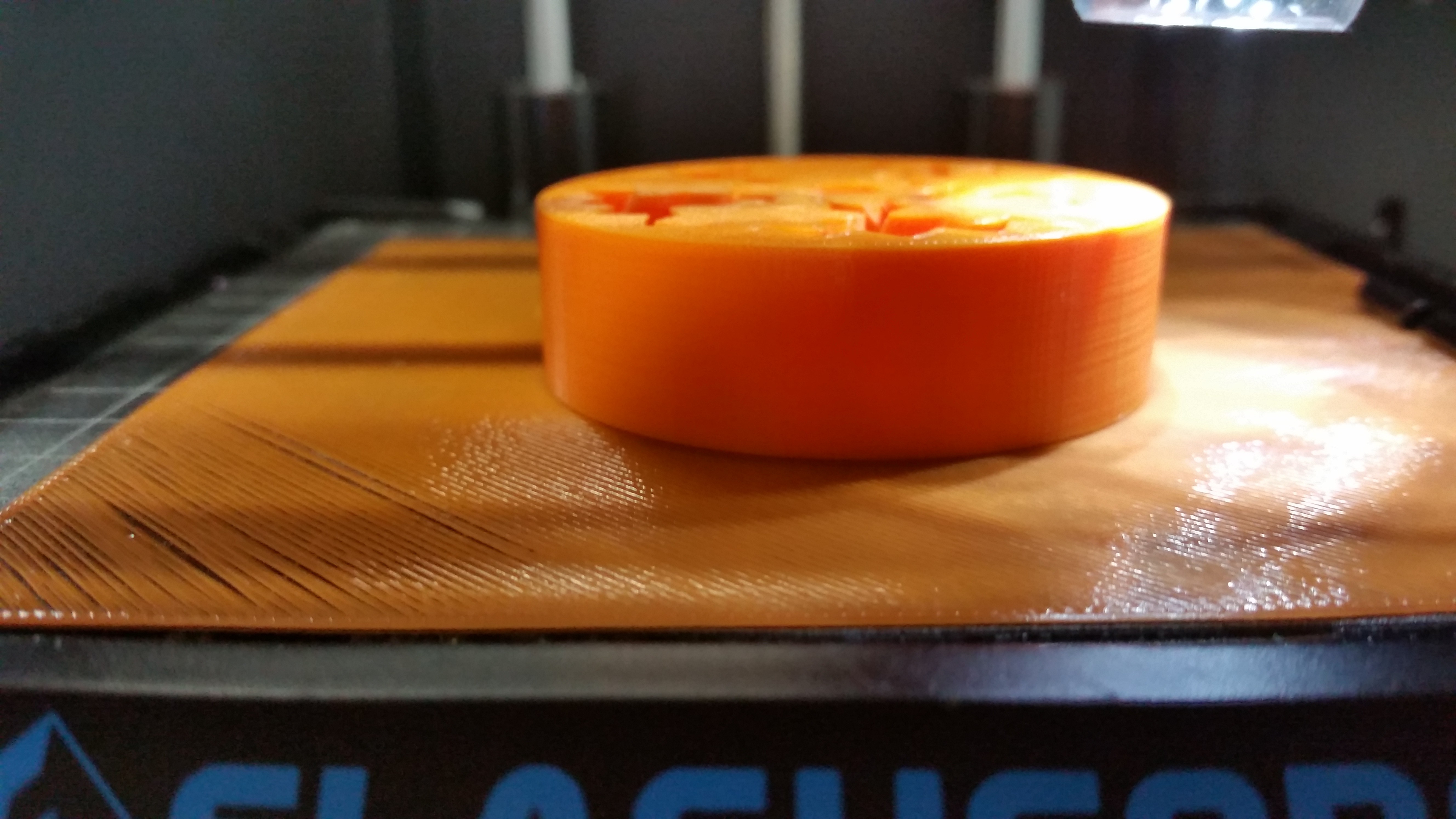
Scan of a 3D print by 3D printer using 3D printed parts
02/25/2020 at 03:23 • 0 comments(YOU CAN CLICK ON THESE, BY THE WAY!)
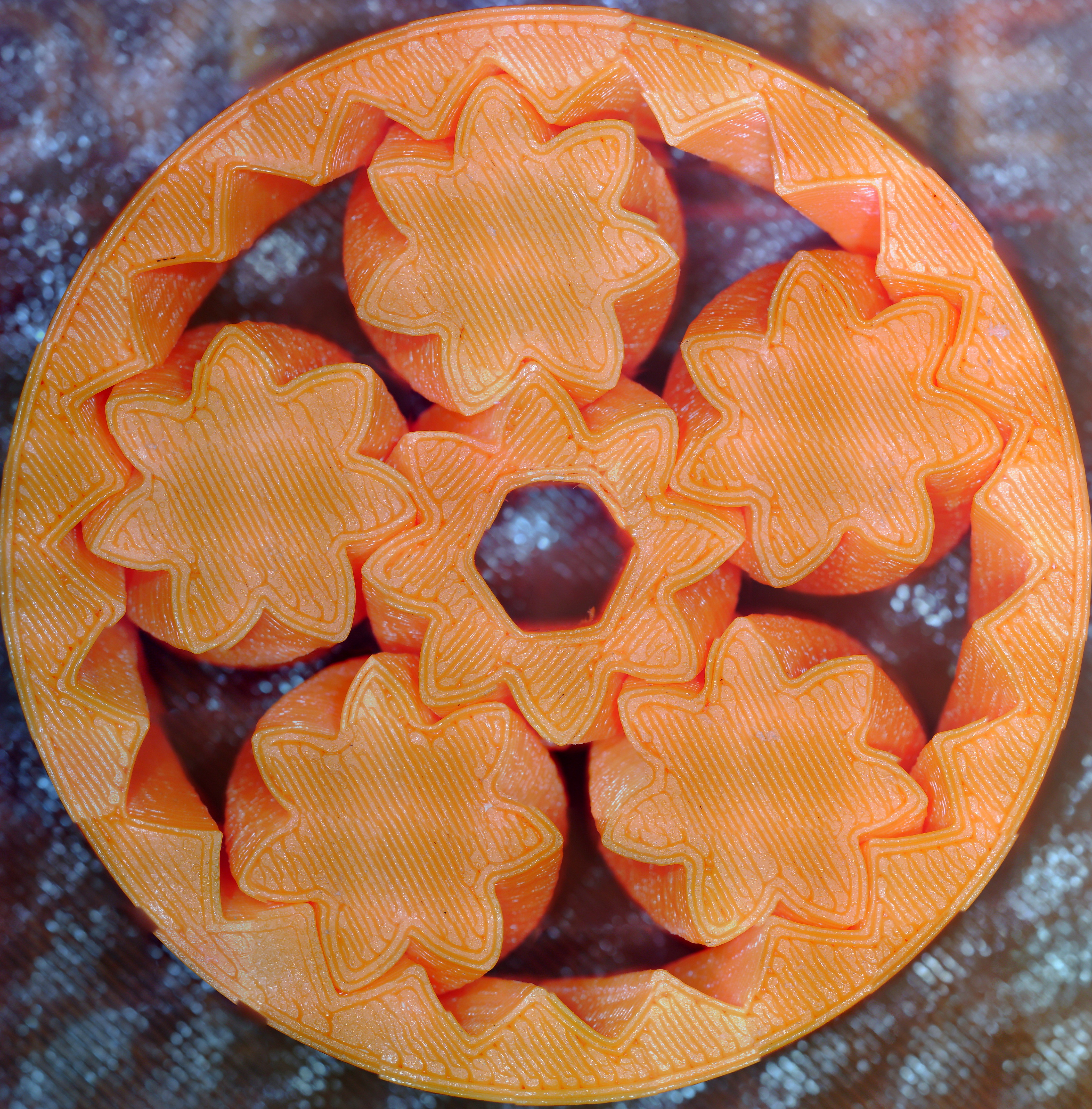
![]()
bout a hundred pics with 25 percent overlap. Color rendition is alright, stitching artifacts are minor, detail is excellent.
![]()
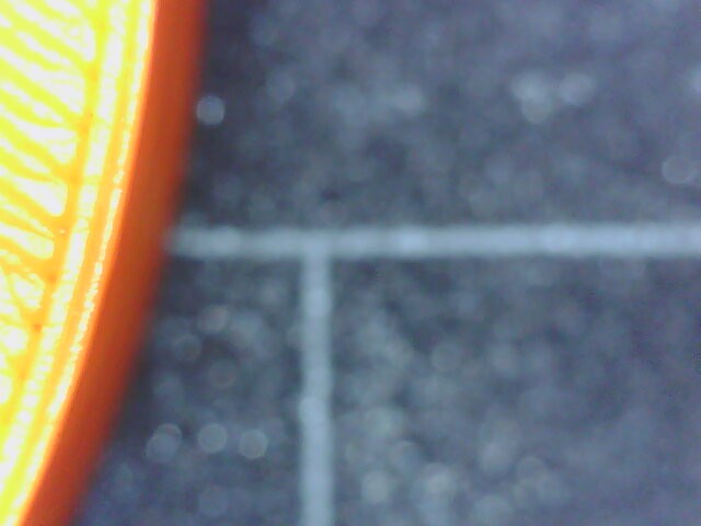
And there's a trick for getting fewer exposure problems! Rather than using the black plate background and getting that autoadjustment issue around corners, I happened to have a printed sheet of the same color filament I could just slip underneath. It actually makes a pretty big difference:
![]()
![]()
Of course I also took a max focus image of a section, though I got it a bit wrong --- I wanted just a gear.
![]()
Also about a hundred pics with 25 percent overlap.
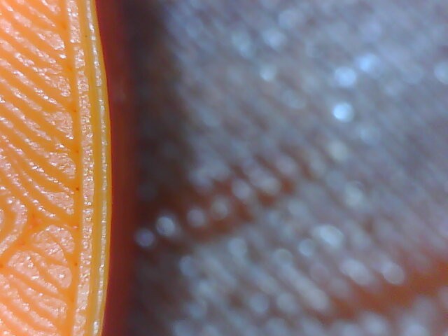
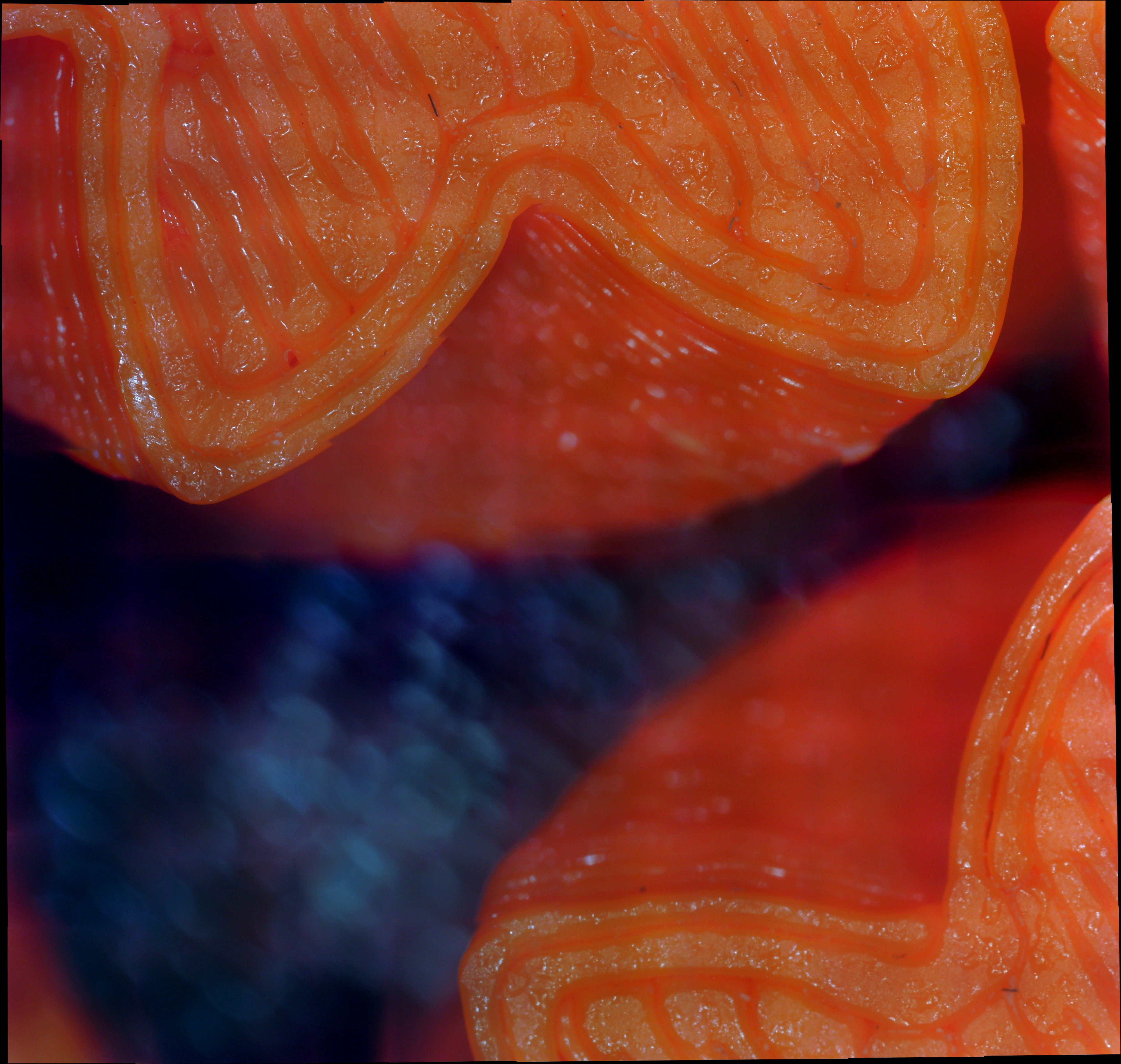
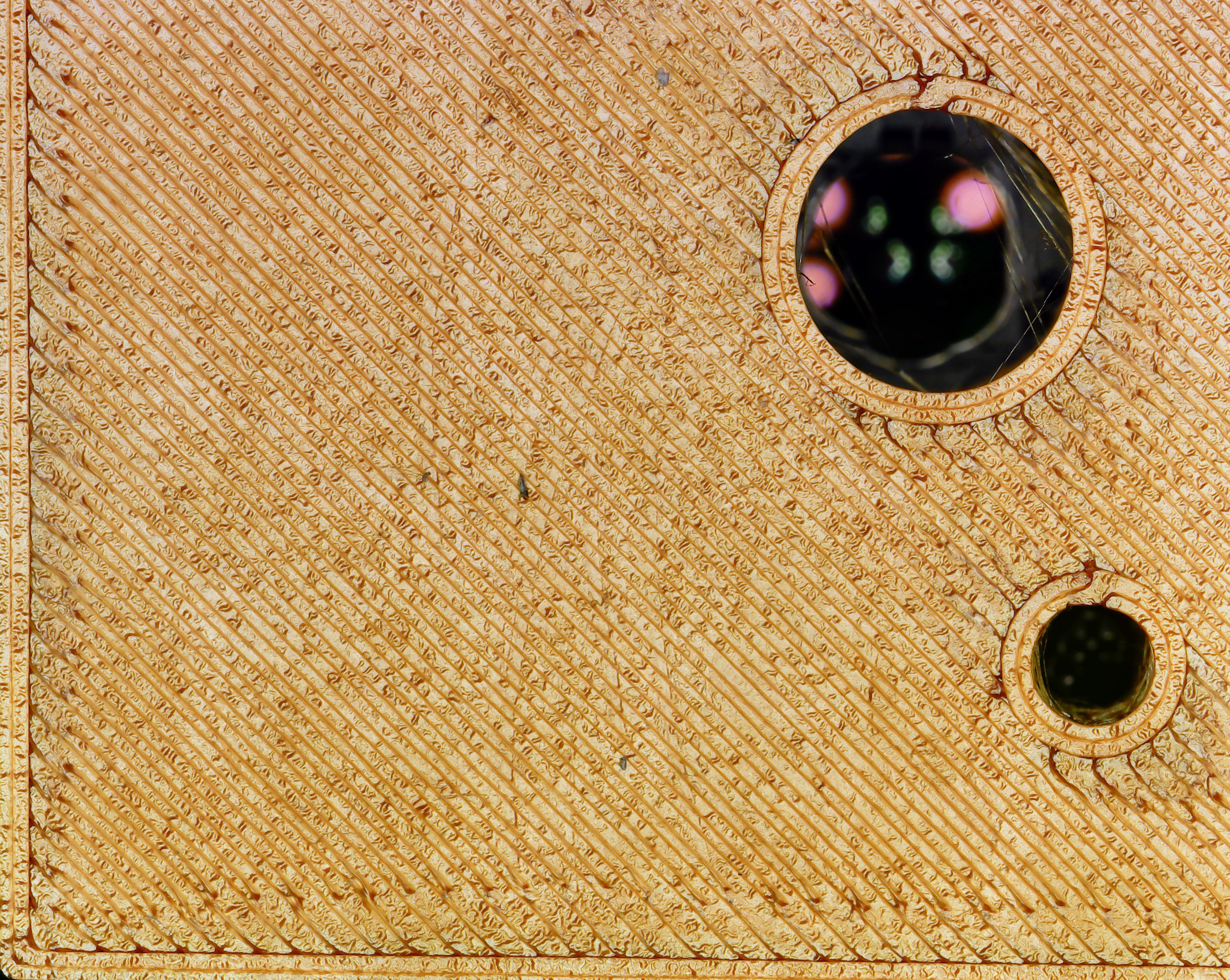
And since it's relevant, here's a scan by the original ladybug, of its own stage.
![]()
It's interesting to compare the squished, oily look of the orange plastic, which was the first layer printed onto a build tak, and the gold top layer of PLA, which gets duller and crumplier as you zoom in. Something something heat and expansion and a place to go!
-
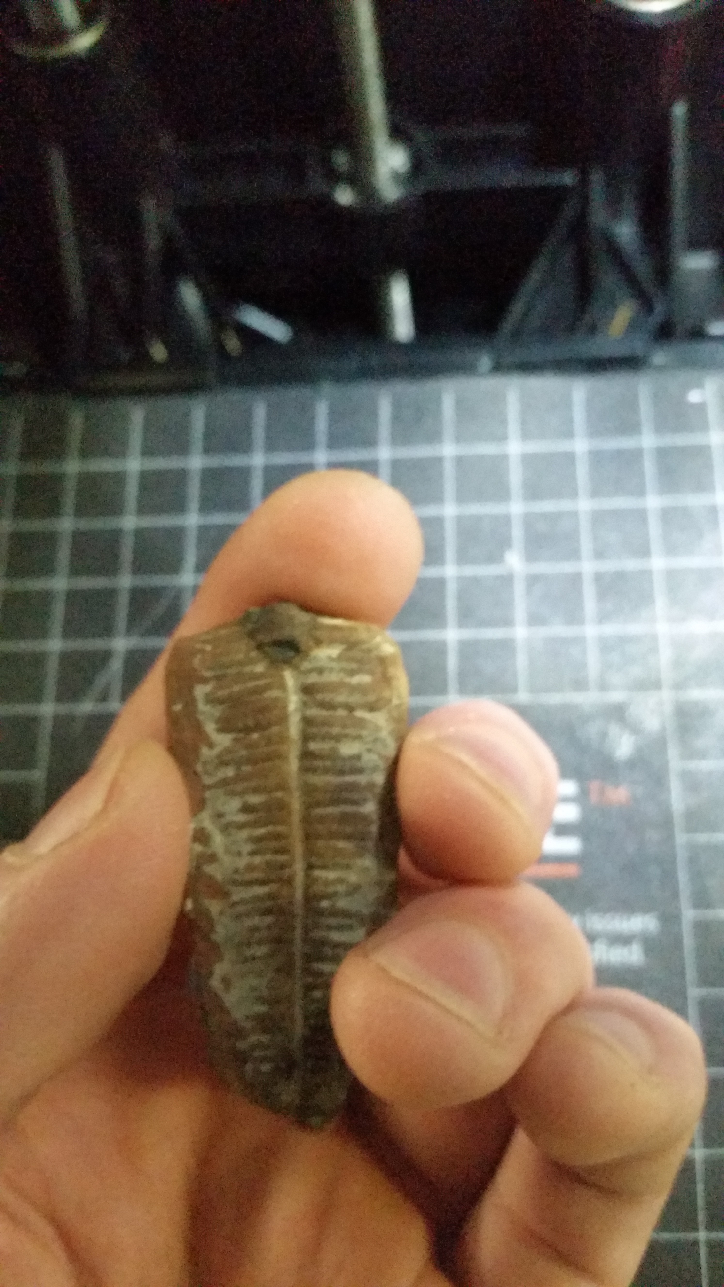
a fossil
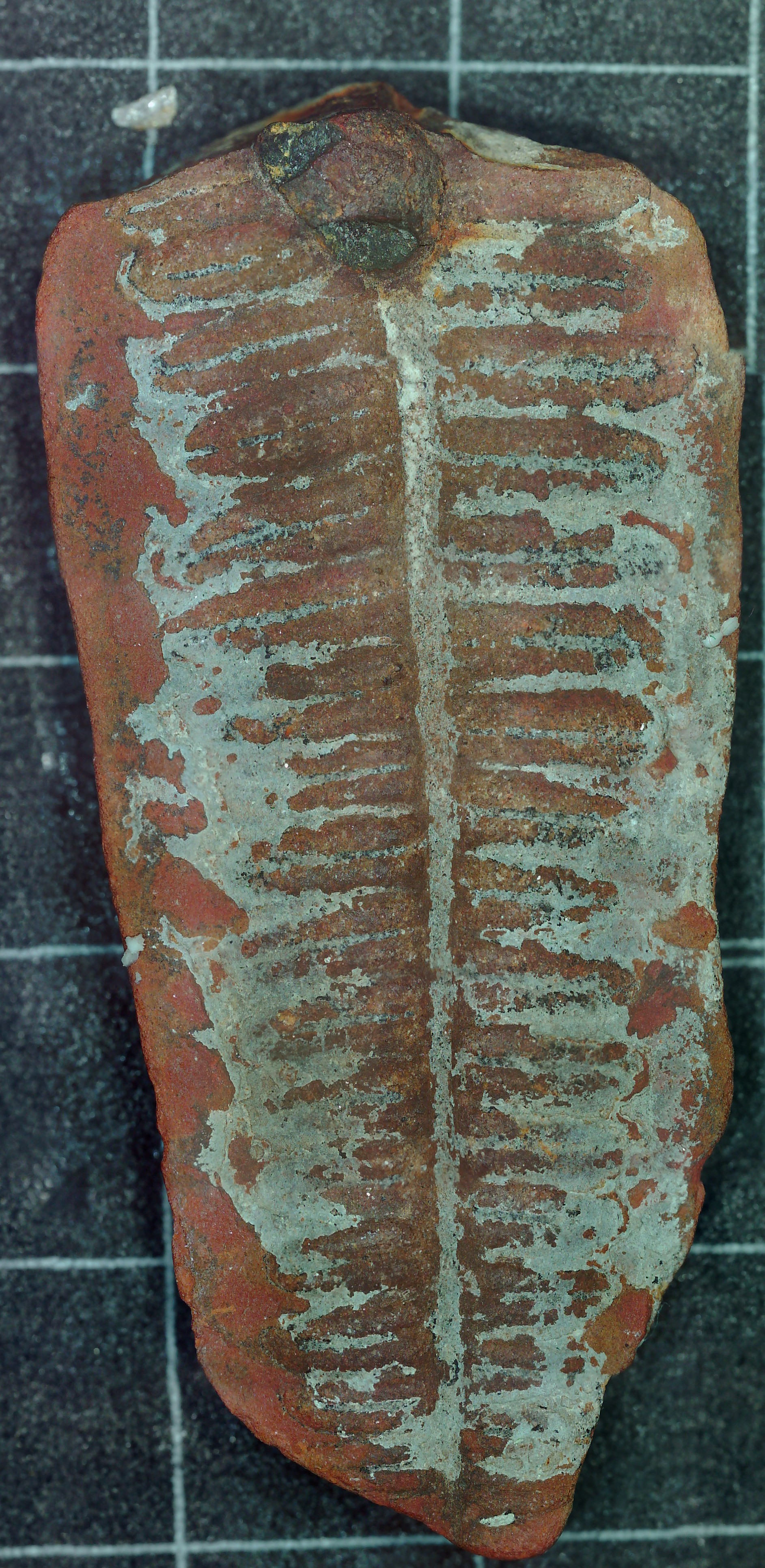
02/22/2020 at 22:55 • 0 commentsI could probably skip the whole scanning process if I could take better regular pictures than this:
![]()
"But the results are worth it!"
![]()
I'd be wary for quantitative-paleontology, but that looks pretty decent! I feel like scanning this way shortcuts a whole lot of stuff about photography and lighting that I never really figured out. You could hand me an expensive DSLR or whatever and I really couldn't get a better image than this, megapixels be damned.
Fun fact, I used 2 Z heights and just flipped back and forth picking the good ones by hand.
-
another rock
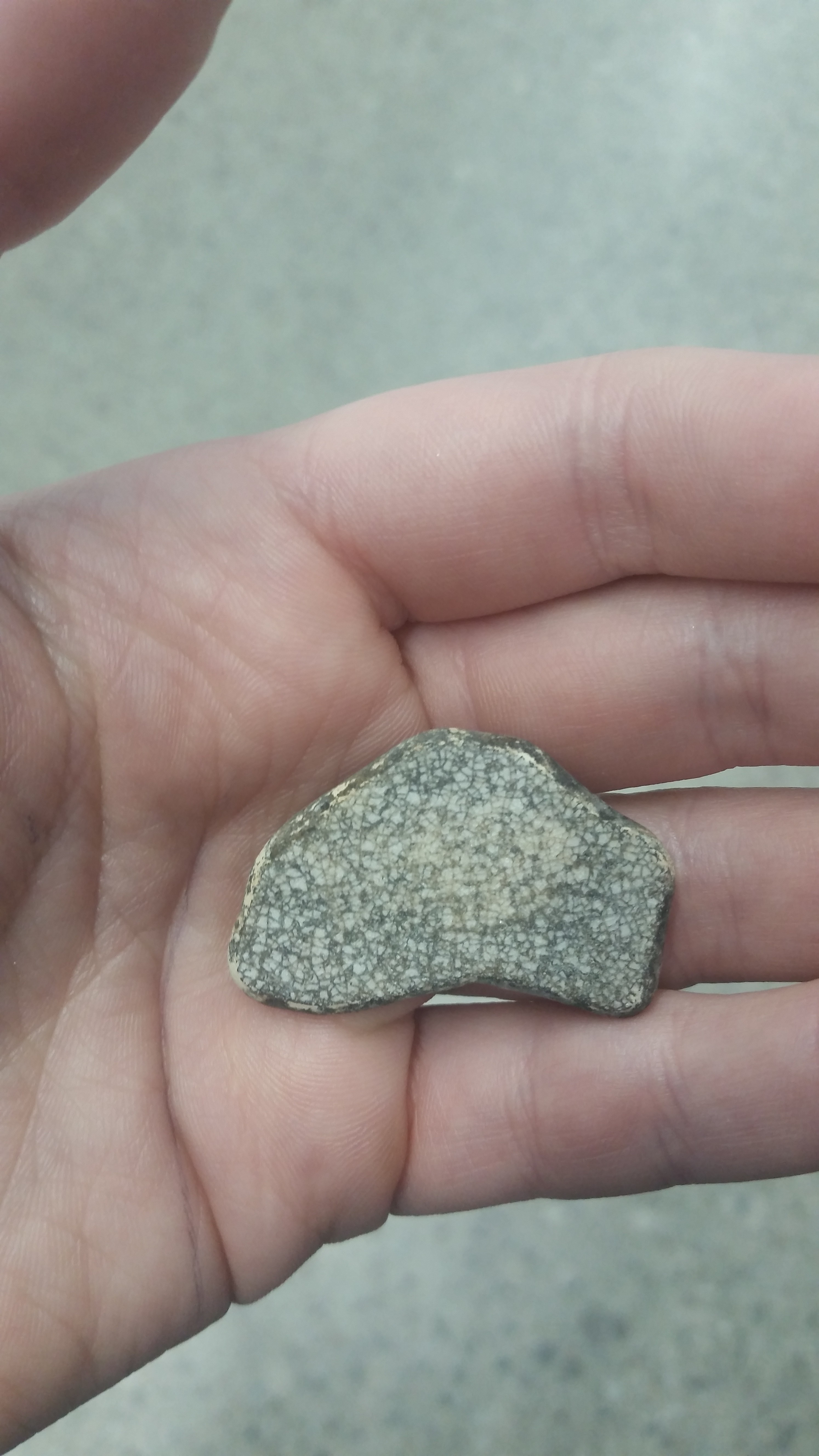
02/21/2020 at 20:04 • 0 commentsEmboldened by the success of the last rock, and driven by the potential for geological applications, of which there are many, I went and gathered some rocks from my house. Some of these are just random things picked up while others I borrowed from the resident ex-geologist. Being flat was the most important thing.
I also spent time calibrating my system, instituting crude-but-better speed controls (for instance, if moving only a few steps, not blasting it as fast as possible and causing vibrations). I also determined how many pixels displacement per step there were at different focus/magnification configurations, which would let me calculate percent overlap in the X and Y dimensions for each picture. I've been going with round step number up until now, but it's better to use round displacements instead.
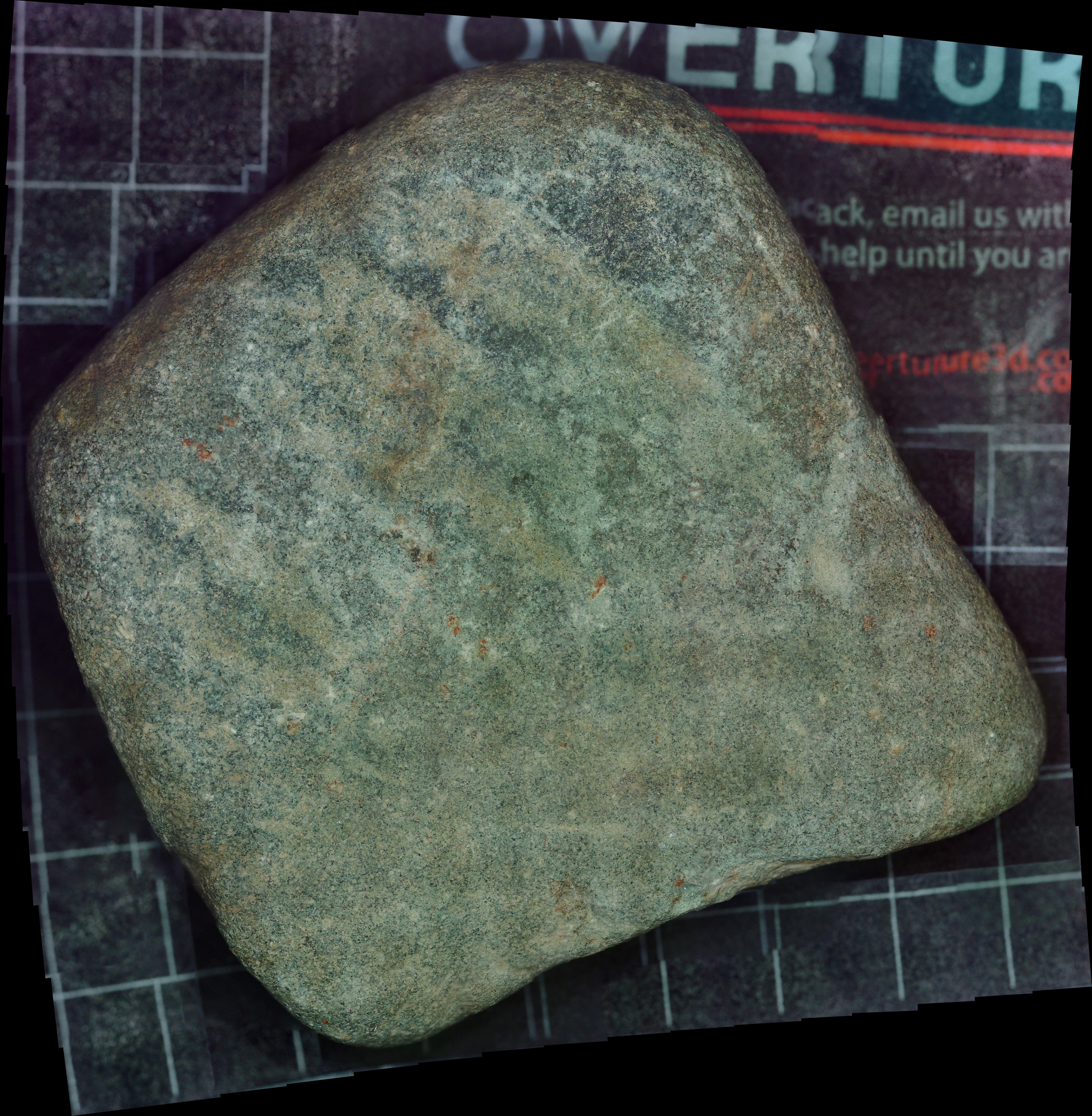
Here's a rock:
![]()
And this is it scanned at "low-medium" resolution, or 1 pixel per step displacement, with just 10 percent overlap between the X and Y dimensions each time (just 9 pictures):
![]()
See that obvious squareish darker area? That's a downside of having very little overlap each time. An image halfway over the edge (and thus partially viewing the black build plate) will tend to have a higher exposure and the rock at the edges will appear brighter than it actually is. Using more overlap helps the stitcher build the colors into something more natural:
![]()
This is 50% overlap (25 pictures) and the dark spot is there but a less obvious. The obvious downside of increasing the overlap is the scan and stitch time, but another is that it can result in more feature blurring. That's because the stitcher is not perfect and every time two overlapping images are combined, some information is jumbled. It's not very obvious in this case, but if local shape veracity is more important than color, you should aim for as little overlap as possible.
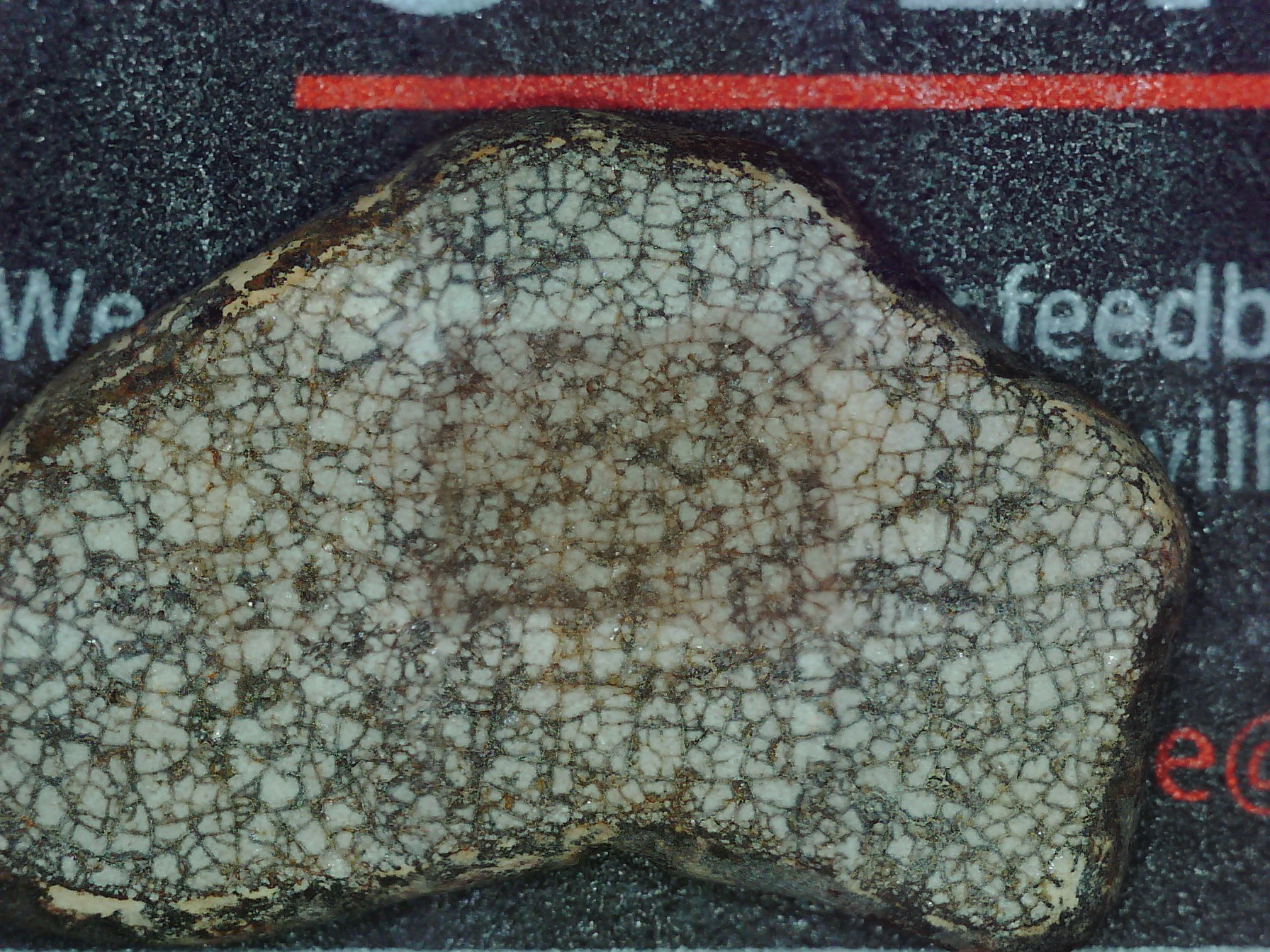
25% overlap seems like a good compromise. Here's that with closer viewpoint so that you get so that it's 1.5 pixels/step:
![]()
They're clearly the same rock, but with some differences, mostly in color. Overall, this picture appears more brightly colored, possibly because the light source is closer. There is also a bit less contrast between the dark and light veins. And there are areas of dramatic color differences, most notably in corners and bumps, like at the top --- I wonder if it has anything to do with the autoexposure being triggered by the red stripe?
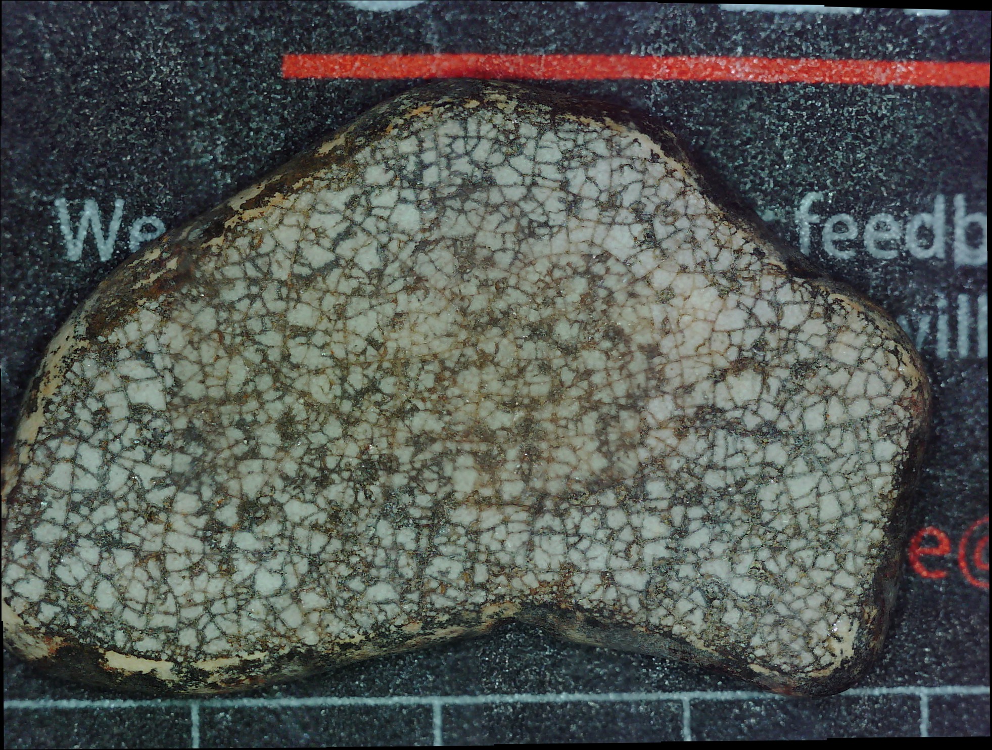
And then we've got the really exciting one, high resolution 7.5 pixels/step and 725 pictures selected from 3 Z heights (compressed from 100 to 5 megabytes of course). The rock actually moved a bit between Z heights (vibrations) but it was all able to figured out mostly alright:
![]()
That's 4 hours of my time right there for you.
And just as a reminder that the above image is composed of ones like this:![]()
-
a rock
02/21/2020 at 00:15 • 0 commentsthis is a rock
![]()
here is a compressed scanned image of that rock (250 images picked from 1250 at 5 Z heights cuz rocks are bumpy)
![]()
-
Fabrics (pt 3)
02/13/2020 at 22:33 • 0 commentsI already scanned these things so I might as well share them, right?
First up we've got a piece of fuzzy blanket:
![]()
Fun fact, this blanket kept me warm in the labs which we keep at 20 Kelvin, until one day a student used it in a Wearable Technology project. Bastard.
There's the high res version (2k pics over just the center) trying to be stitched:![]()
And there's the stitched version, reduced from a 70 megabyte jpeg to a 4.9 megabyte jpeg to meet Hackaday's 5 megabyte file limit. Honestly, it's not too terribly compressed except for when you look really close, which I guess is the whole point to scanning things like this.
![]()
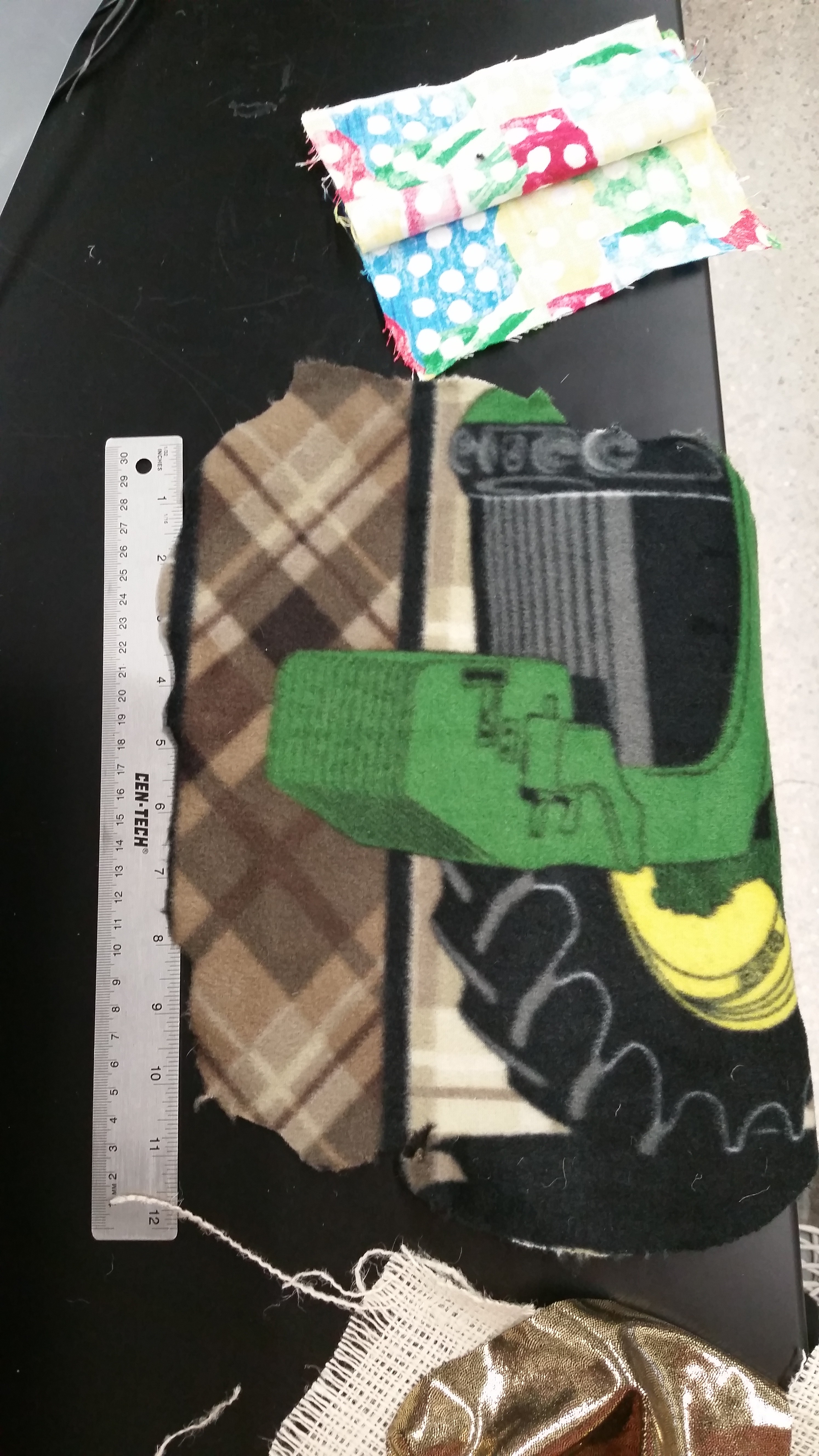
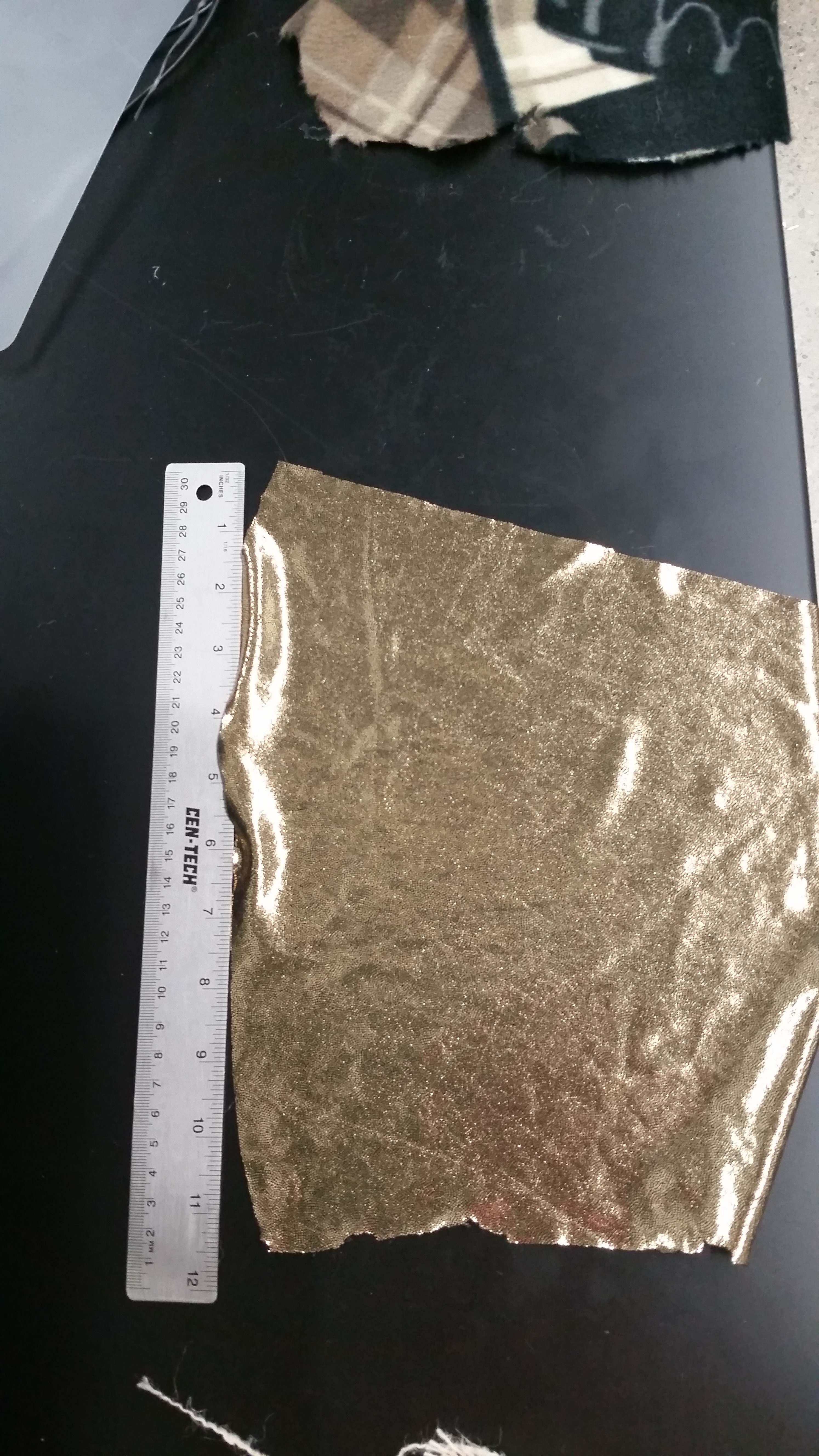
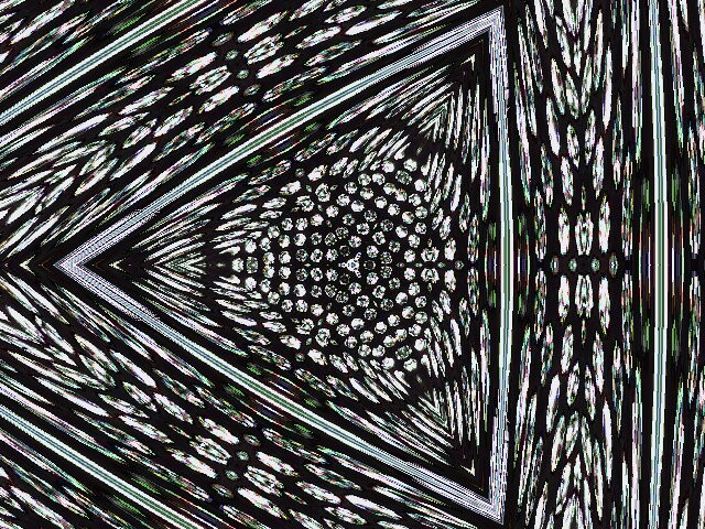
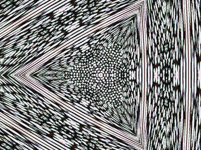
And then we've got some stretchy gold sequin fabric. This one was interested to scan because it reflects so much light it looks just white, then you zoom in real real close and it's gold again.
![]()
![]()
![]()
(fun with linux Cheese's kaleidoscope function)
![]()
This is definitely one of those cases where the moving lightsource makes things wonky, or possibly opens up the opportunity to do something artistic.
And closest up version, likewise reduced down to 5 megs:
![]()
I like this one because you can see that there's actually a lot of empty space between the sequins were the black fabric is visible. I would like to visit a material like this again sometime to see how you might get accurate (to a human) color rendition so up close.
If you thought this post was neat, please consider sharing it to someone else you think might be interested, too.
-
Stacking and tilt images
02/06/2020 at 00:21 • 0 commentsDespite having the ability to theoretically, I've never done true Z stacking by combining images. The other uses of Z height change was to pick between focused images, not actually combine them. This works okay when the change in height is across different x/y regions, not when there are changes of height within a single image.
With the rest of the post keep in mind that the usb microscope outputs images at 480/640 pixel resolution. Stacking and then stitching is a whole other ballgame that I think is possible but is a bit more annoying with my current image processing pipeline.
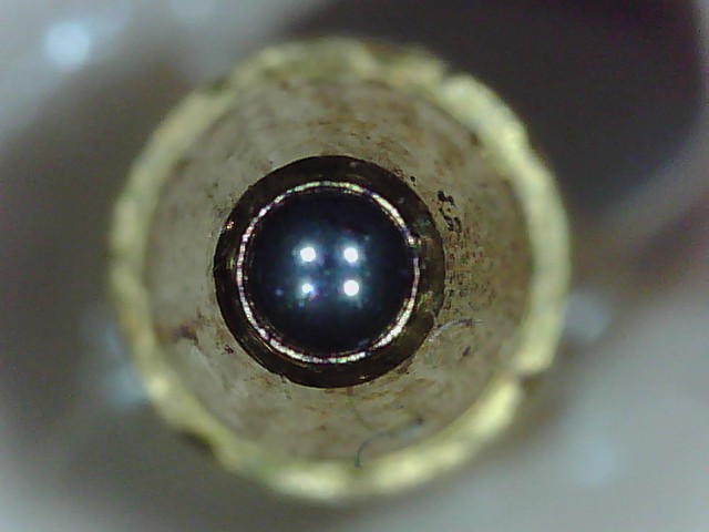
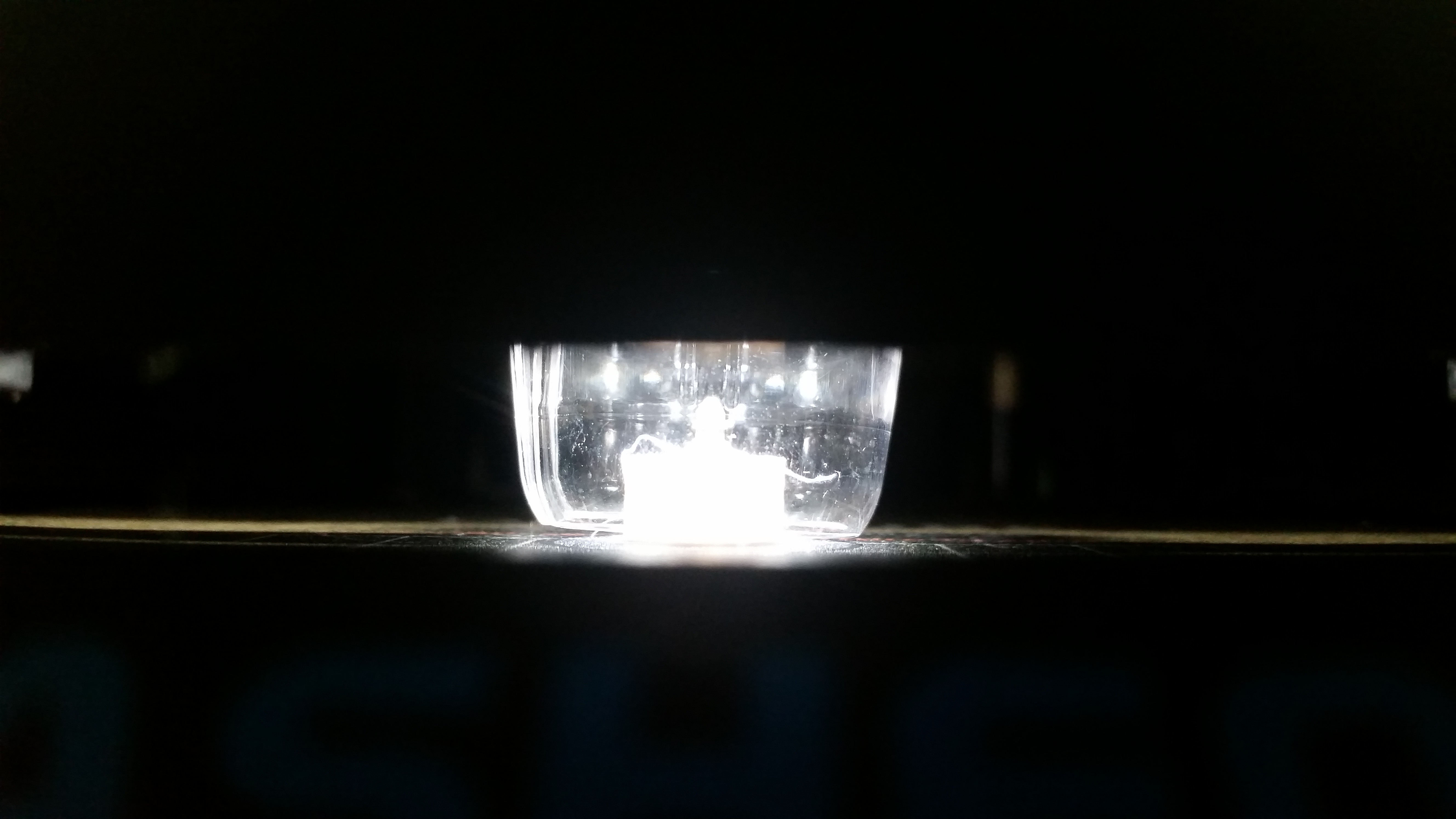
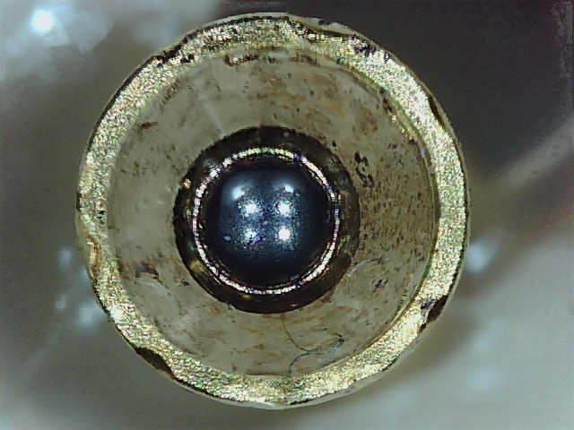
Anyway, what is this thing?
![]()
Here's a not so helpful hint:
![]()
If you guessed "ballpoint pen tip", you'd be right! Except a pointy object facing straight up is the worst kind of thing to look at if you have a narrow depth of field. Clearly, there are parts of that image that are in focus, but it's a thin section. Enter moving the bed up 100 times in 50 microns increments:
![]()
(this sequence is compressed a bit to fit hackaday's 5 MB limit, but you get the idea).
One thing of note is the pattern of illumination, thanks to the scope's always-on LED array. This is also a regular artifact of 2D scanning, and needs to be addressed by, for instance, flooding the entire area with a huge amount of diffuse light. But gimme a break, I'm one person with like no budget.
Stacking was done using Picolay with no human input:
![]()
Hey, that's not too terrible! It does look kind of strange because, as intern's intern put it, the middle looks like a hole and a mountain at the same time. It's hard to tell what you're looking at. I'm not sure if any of the striations or blurring are caused by the images and illumination or the stacking process itself (whether they're fixable at the software or hardware level). but this is definitely a stacked image, with everything pretty much in focus.
![]()
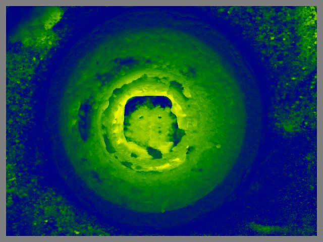
That's an auto-generated depth map, but I'm not really sure what it means.
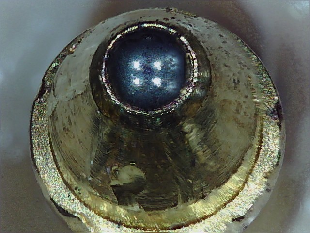
Then, after adding a regulator to drop the voltage going into my rotary motor from 24 to 12 volts, because it was running super hot and I used hot glue to mount the pen tip, I tried looking it it from a couple of different angles. I used the rotary tool but didn't program a scan really, just tilted it a couple of times and then stacked again each time:
![]()
Now that's interesting! You can see much more detail, like those gouges on the metal.
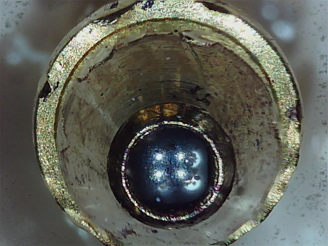
And the other side:
![]()
And, finally, a gif showing the stacking process, which I thought looked really cool:
![]()
-
A fourth and fifth axis adds no slop
01/31/2020 at 00:06 • 0 commentsIn the original LadyBug, I used a teeny tiny stepper motor to add rotational capability for not just 2D scanning, but 3D scanning of a small sample:
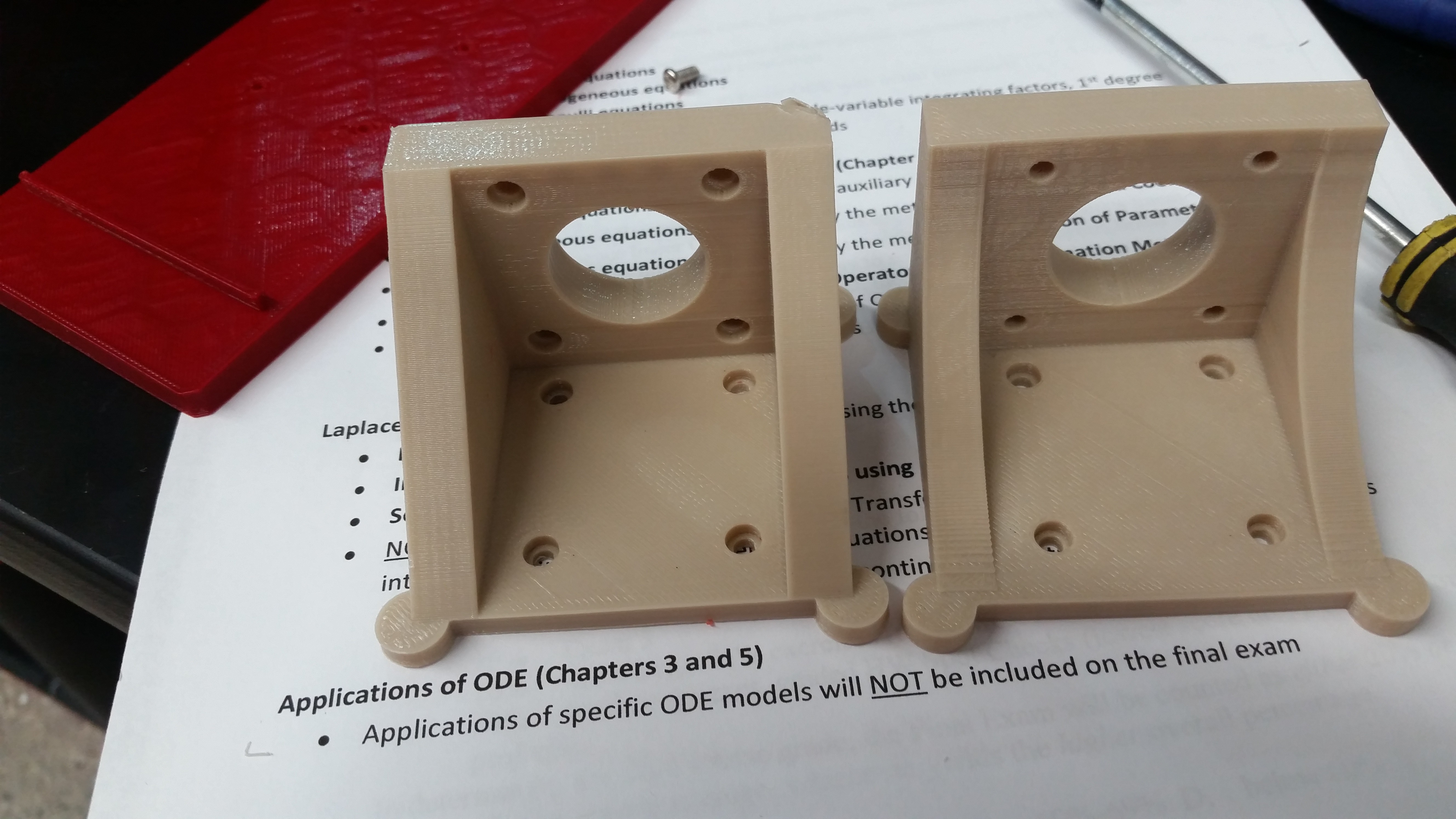
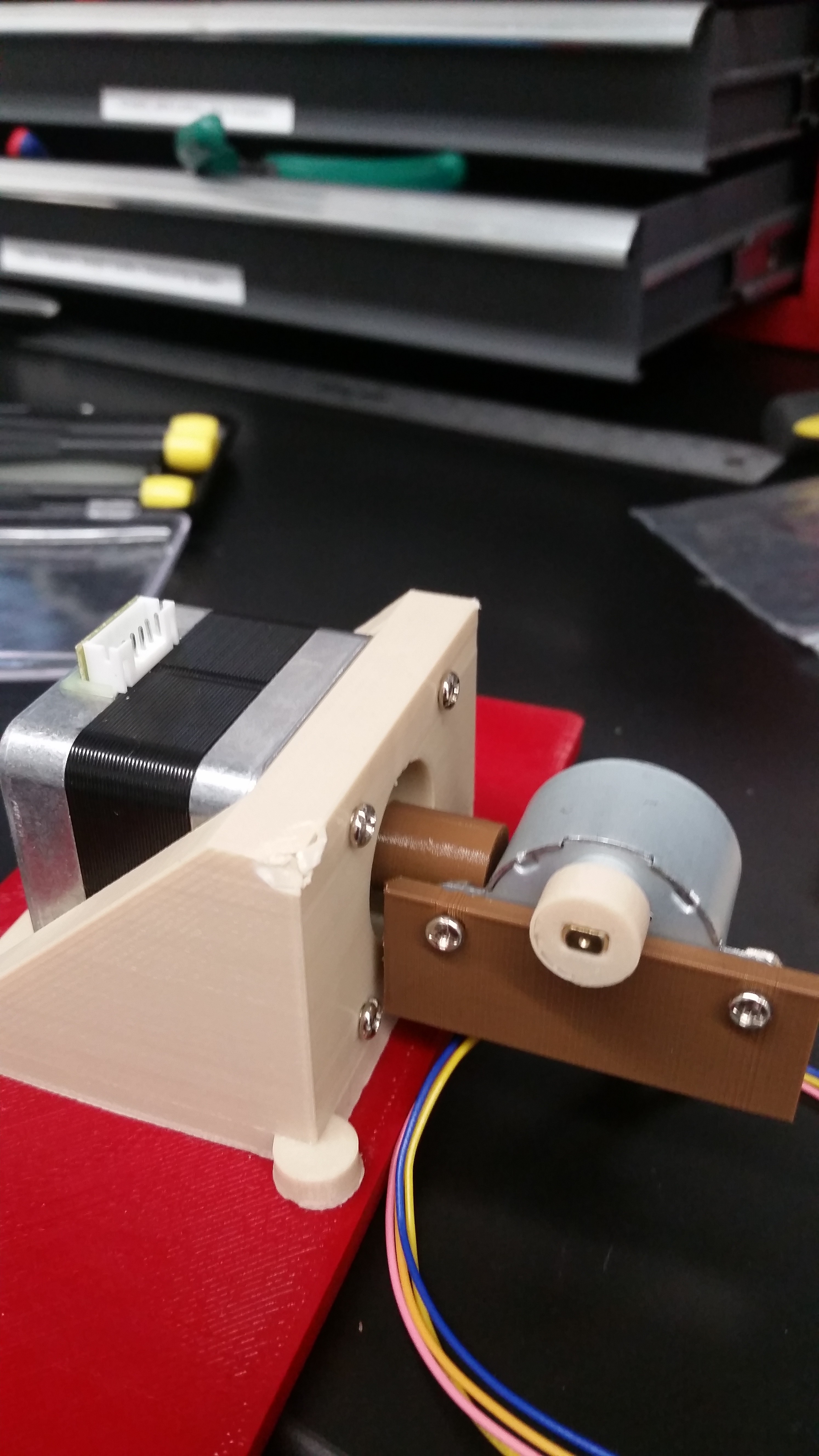
I wanted to do the same thing here. So I made a bracket for a standard Nema Stepper motor:
![]()
(first version to left had big old triangles that got in the way, and recessed holes were on the wrong side. Fixed on the one on the right).
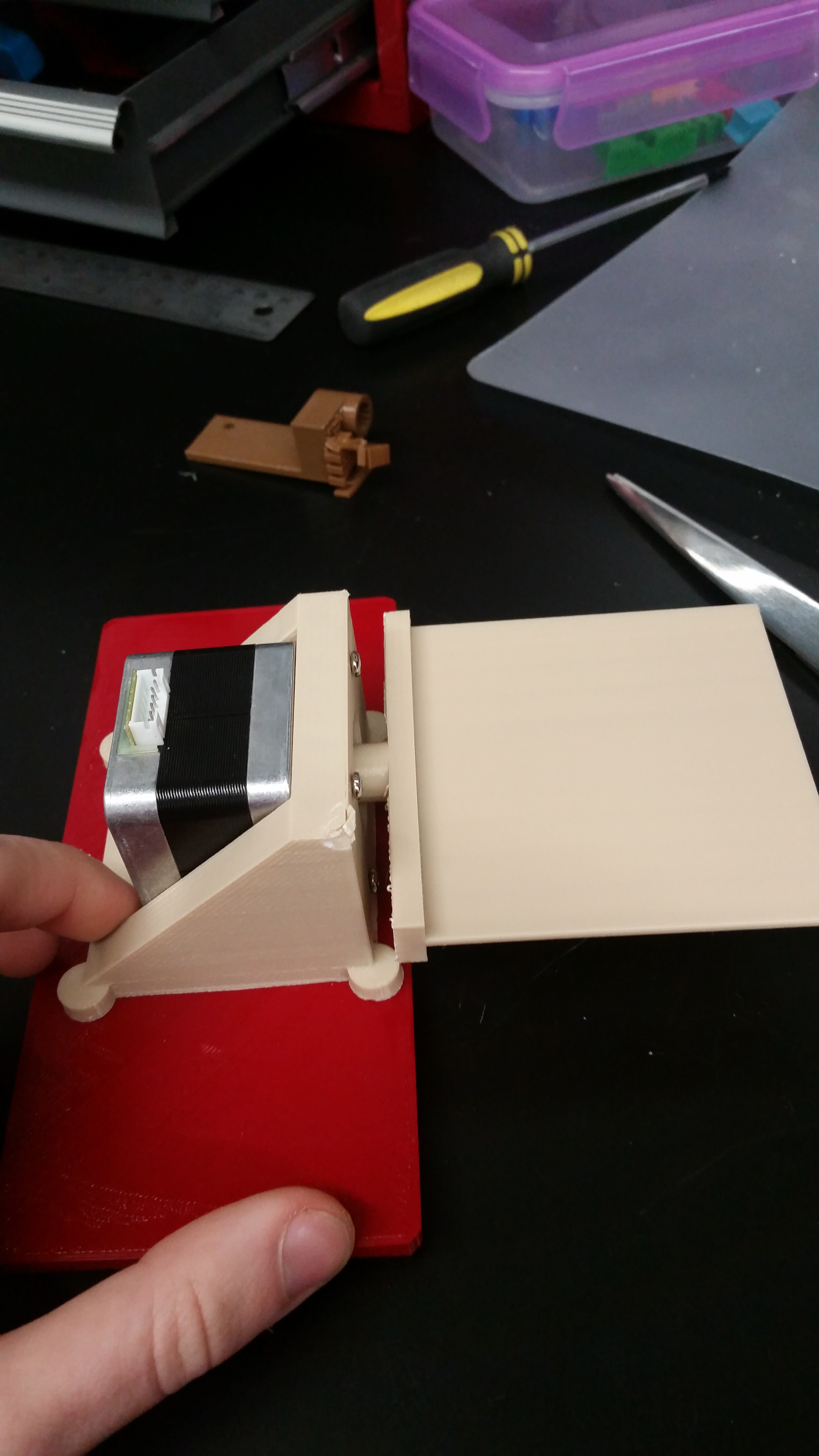
The bracket screws into the red piece on the background, which I made to fit into where the removable printer build plate would slide in. Much easier to install and remove for switching back and fourth between 3D and 2D scanning.
![]()
Here it is installed onto the slideable plate, with some kind of flat scanning surface attached to the spinny part. I guess that's so you could build up a 3D image of flat things like textiles? I'm not really sure. I haven't actually used it yet, because I got caught up in making the machine even more complicated to the point of uselessness. I did that, by...
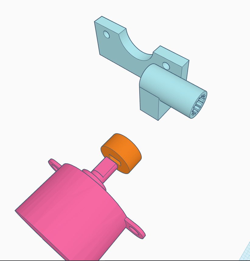
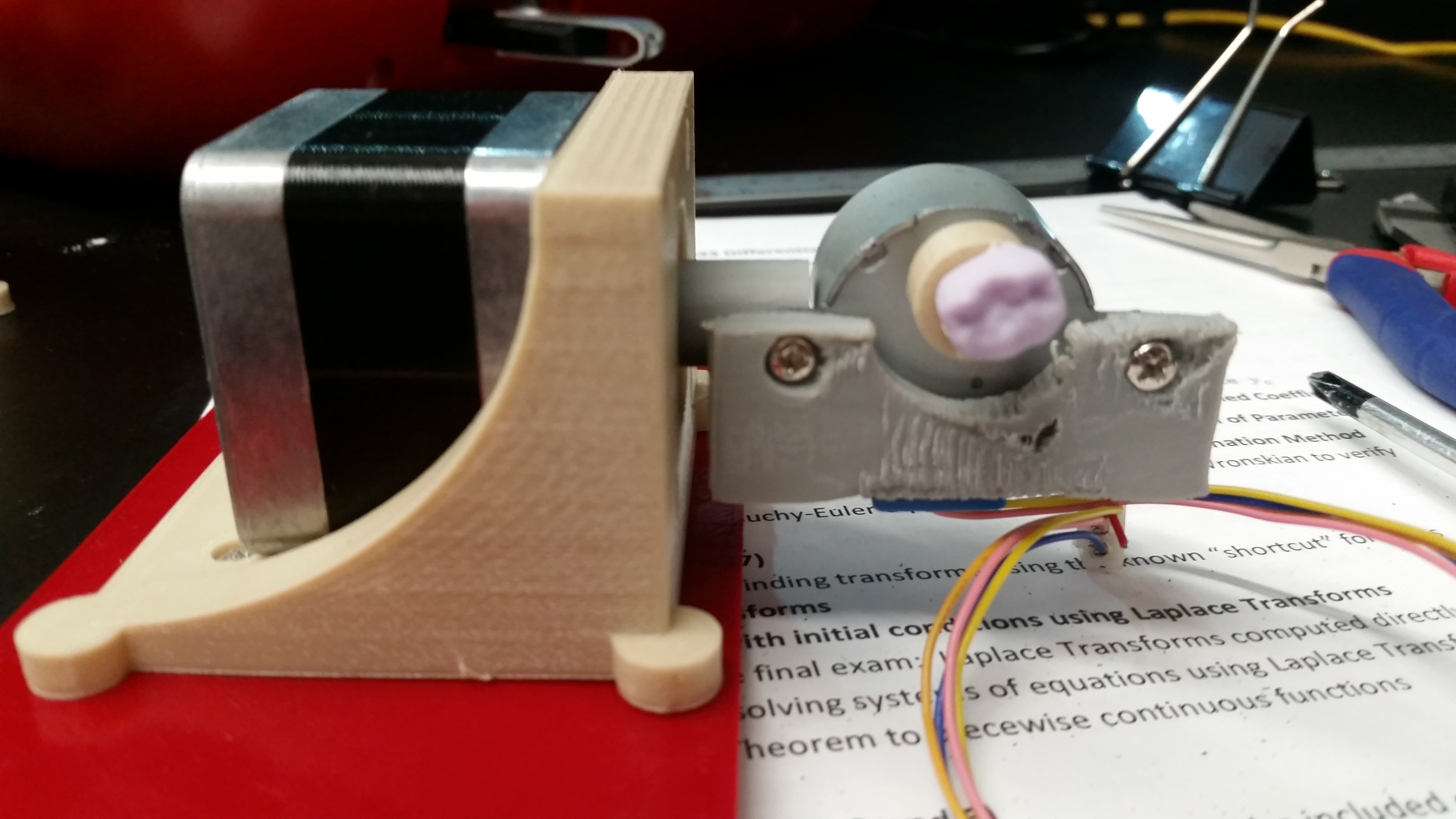
...creating a very precarious and not-printing-optimized piece to attach the output shaft of the fourth stepper motor to a fifth stepper motor. That is, the fifth stepper motor (the pink one) is the one that rotates your sample, and the big NEMA becomes a tilt motor, which rotates the fifth one. See? complicated!
Here it is in nice PLA:
![]()
And here it is in disgusting but functional ABS, after the PLA one melted:
![]()
(that's a prosthetic tooth. turns out dentistry is a lucrative market for 3D scanning.)
Let's cut to the chase: there it is in action.
(PS, this is my first-ever edited video of any kind basically. I'm not good at everything.)
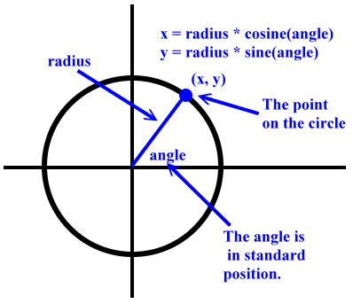
So it absolutely does work as intended, which is neat. One problem which I'm very happy to have solved at its core is eluded to in the video. And that is, if you are tilting something, it is not just going to change the angle, but is going to be shifted in the X and Z dimensions as well. I was aware of this for a few days and just tried not think about it because it looked like a lot of really hard math. But it turns out it's actually pretty simple.
![]()
It's really basic geometry. You're sweeping out the path of a circle. If you know the radius --- the distance from the axis of rotation to the point of your object --- and you know the angle change, which you can figure out based on the number of steps and your stepper motor --- well, that's all you need. This all has to be converted a couple of times between steps and real units, which required me to measure things for the first time, but overall I'm quite happy with how well it works. I'm going to have to calibrate it and maybe make the radius dynamic (it's just set ahead of time right now), but it at least gets you in the right ballpark of where you're supposed to be.
Yeah.
Okay. There you go.
-
Fabric (pt 2)
01/25/2020 at 21:25 • 0 commentsI'll bet you're dying to pour over every scrap of that cloth. I can show you, but it would be in between 3300 and 10,000 pieces.
The problem is not one of repeatability:
![]()
The scan was 3 hours and took place at three different Z heights. The 2D raster scan of 3,364 images each occurred in between the Z height changes; that is, each change in Z height happened an hour apart, in my very sophisticated setup of binder clips holding it stable. The lights in the room probably went out at one point but I encourage you to look at the image above and see if you can spot a difference.
So the image is stable in the X/Y direction, meaning it shouldn't be a challenge to mix/match clear images, or even stack them. I haven't tried stacking in this setup (it's definitely more stable than my last one, where I had trouble), but the blur sorting qualitatively worked without a hitch. Problem:
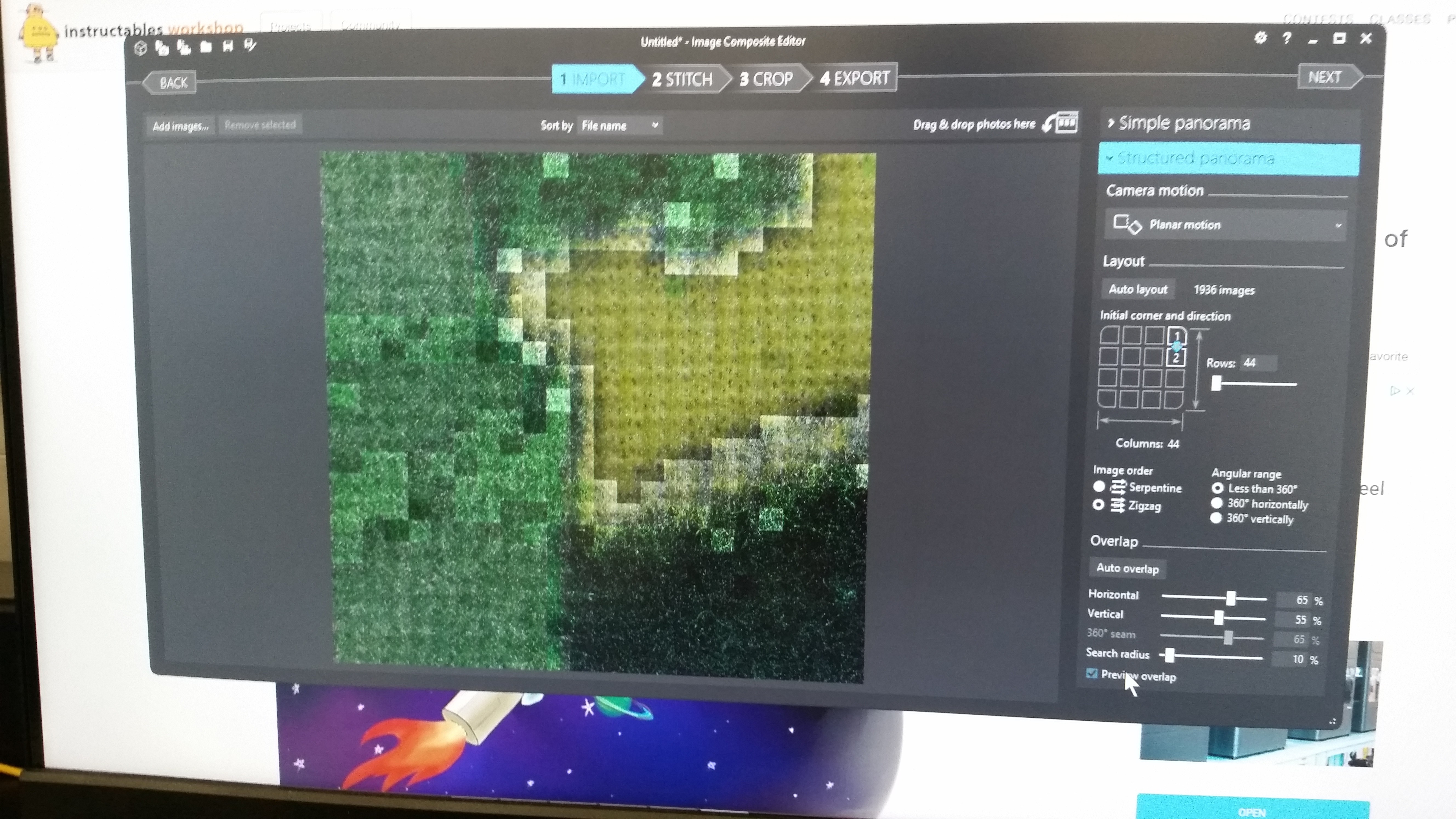
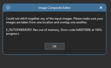
The stitching program hates it!!!Grrr! Argh!!! It's got too many files, or I'm just not mighty enough. It totally knows that it's an image --- the preview looks great!
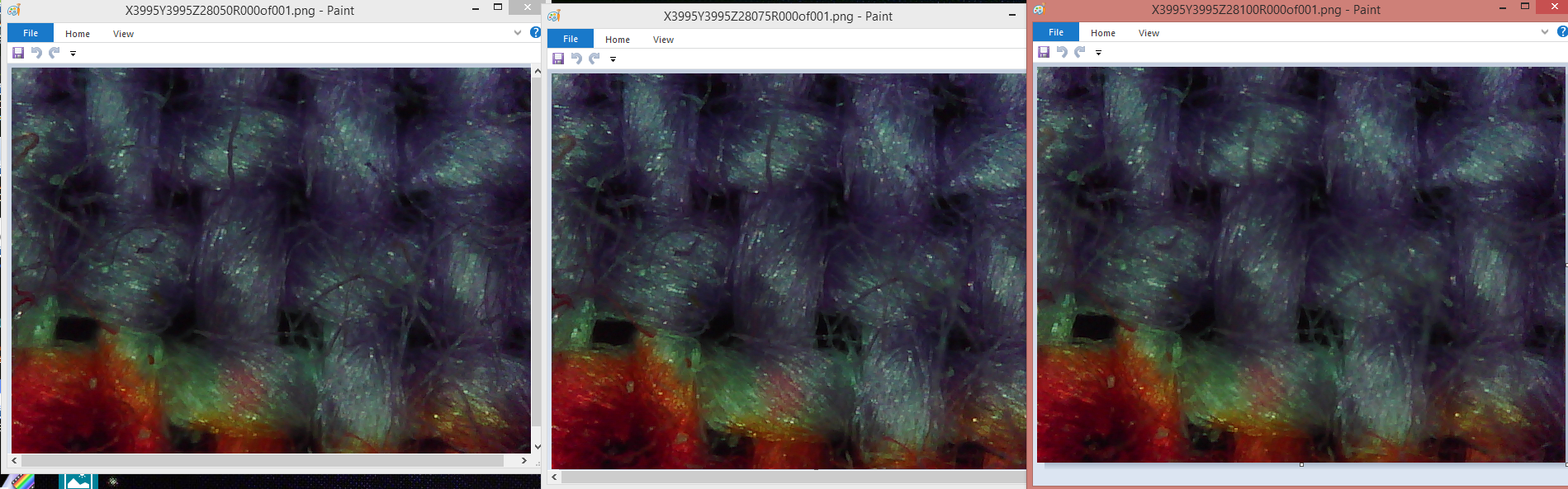
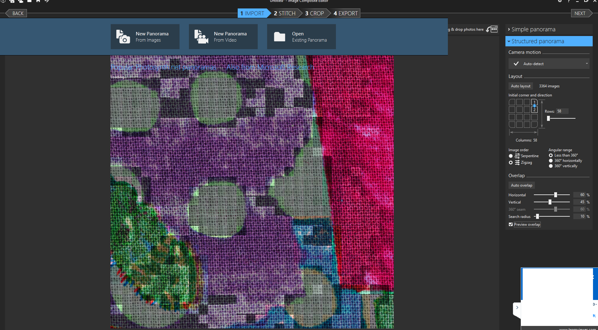
It's not even that many --- I'm doing a relatively small area. Could get to 10,000 or more, easy. Add that to a very limited commandline API, as well as the weird color effects...
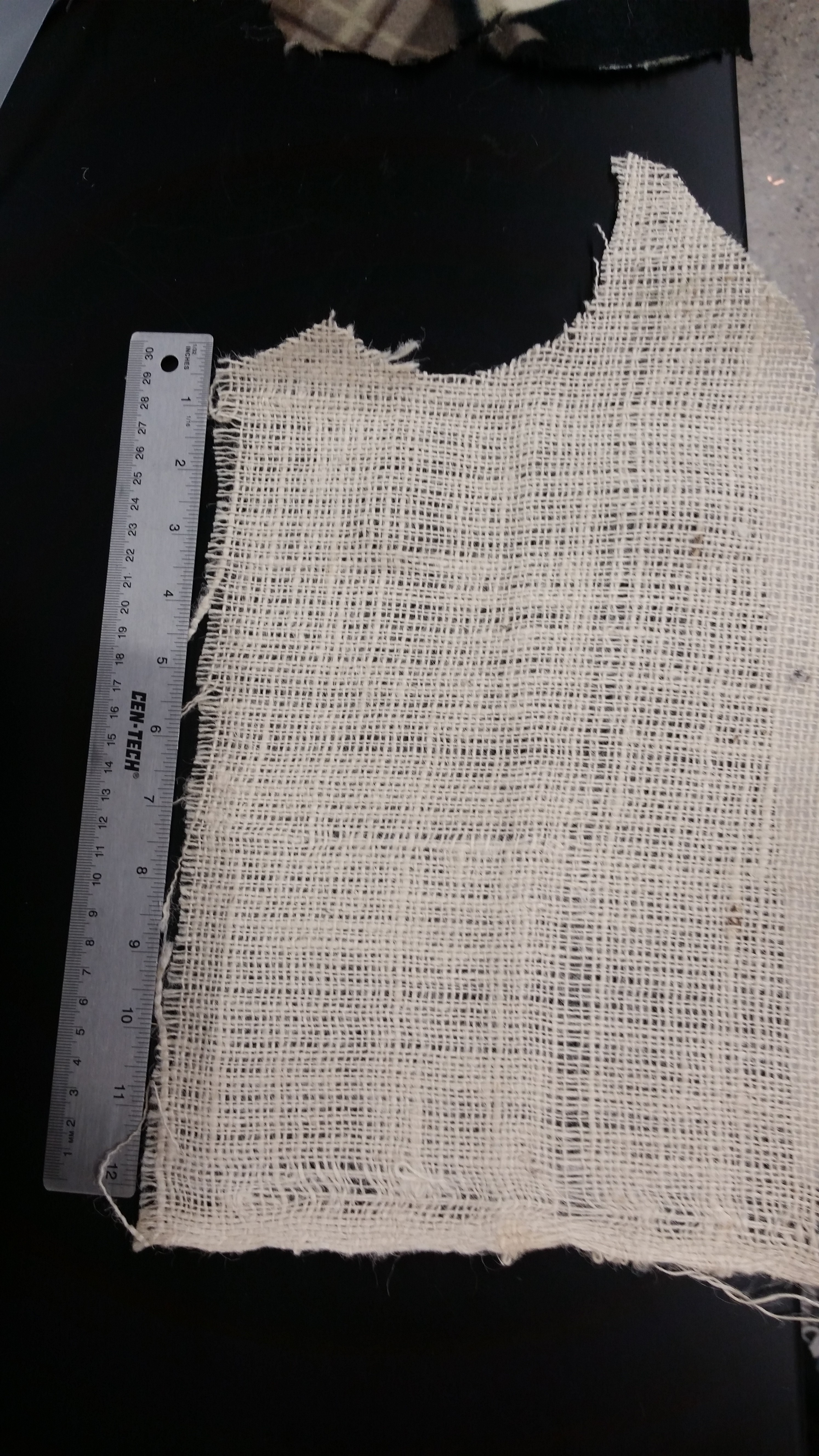
![]()
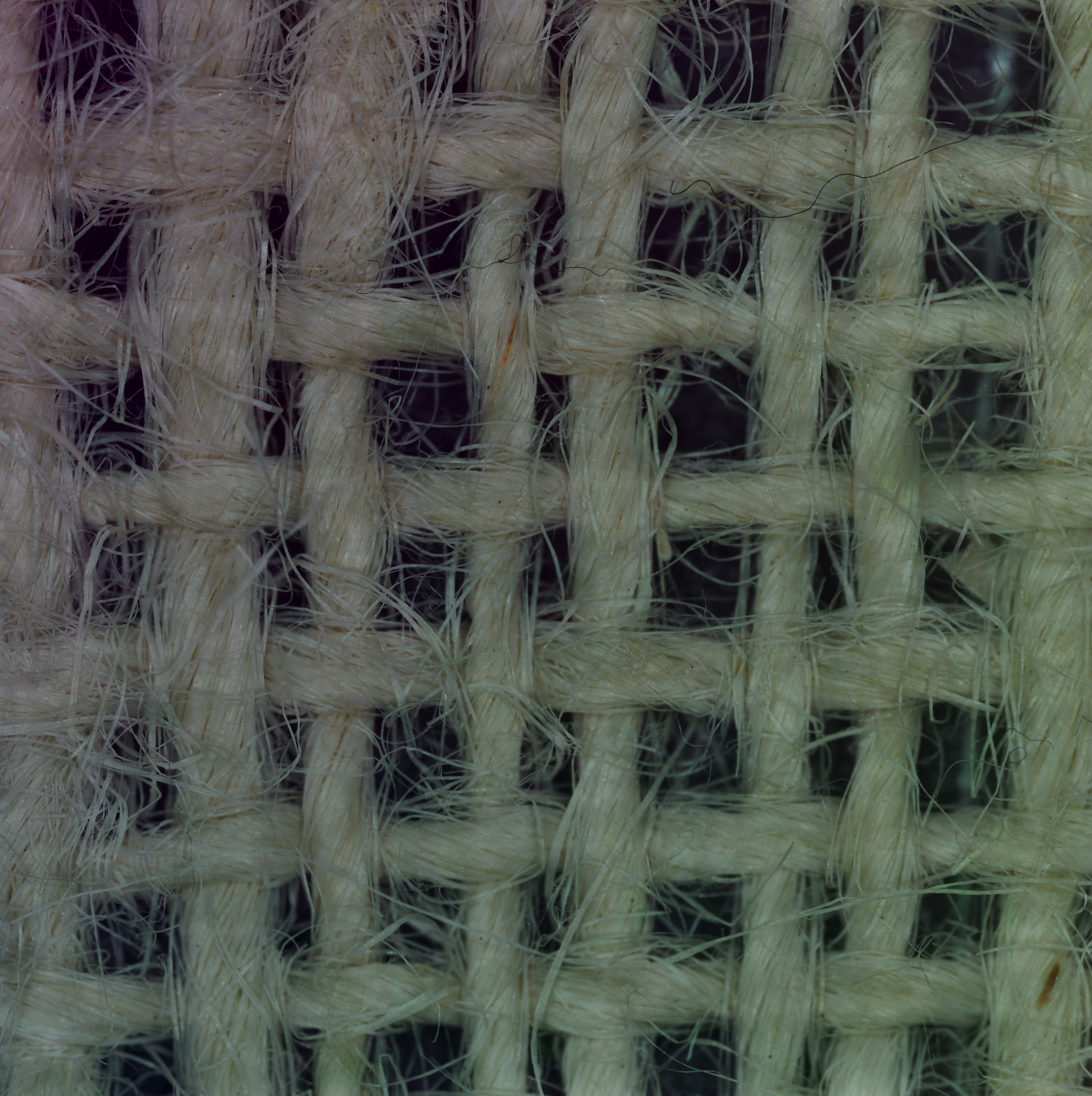
...which is why to belabor my point, I'm not leaving you hanging without a stitched image. That above is some loose burlap which, as you see, is WHITE. The individual images are all WHITE.
![]()
Microsoft ICE has served me well, but it's desperately time to use or construct a good programmatic solution. I don't care what it's in, OpenCV, Fortran, those little candy ticker tape things. But someone. Heeeelp! 救命! F1!!!
LadyBug BEEFY: 3D printer motorized microscope
Got printer? Connect to the motors with a Pi, plonk in a cheap scope, and do 2D and 3D scans!