 bobricius
Tested only with IV6-tubes
AXIRIS IV-3 Shield for Arduino is super great project, specially power supply is very good designed. etc. filament is driven with AC voltage which is recommended for VFD. 12V input voltage is 3x multipled to make 36V I am redesigned board for easier soldering, all components are in lines with same value
- added buttons for HOUR / MINUTES
- speaker driver for make alarm clock, in current firmware is only hour beep implemented
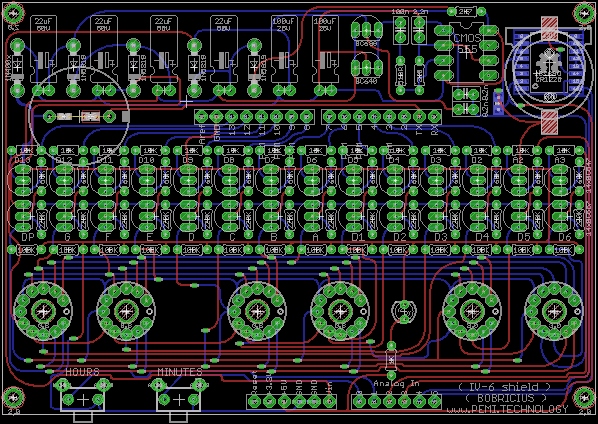
- components values on PCB
- DS3231 with battery backup
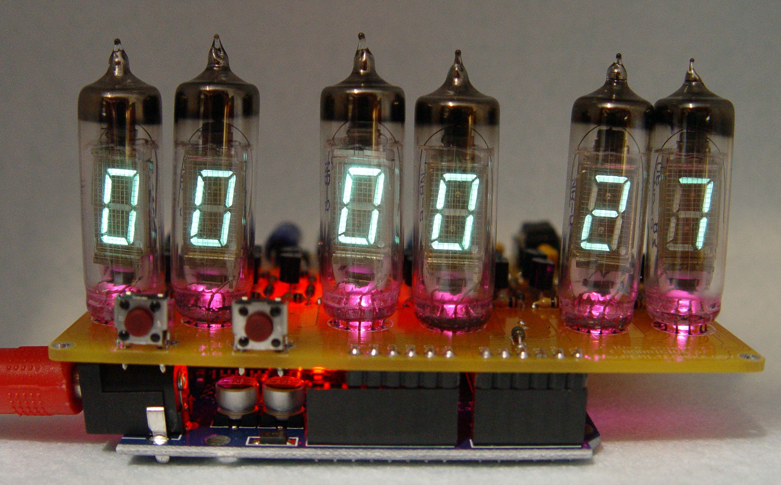
- Enhanced to 6 DIGIT
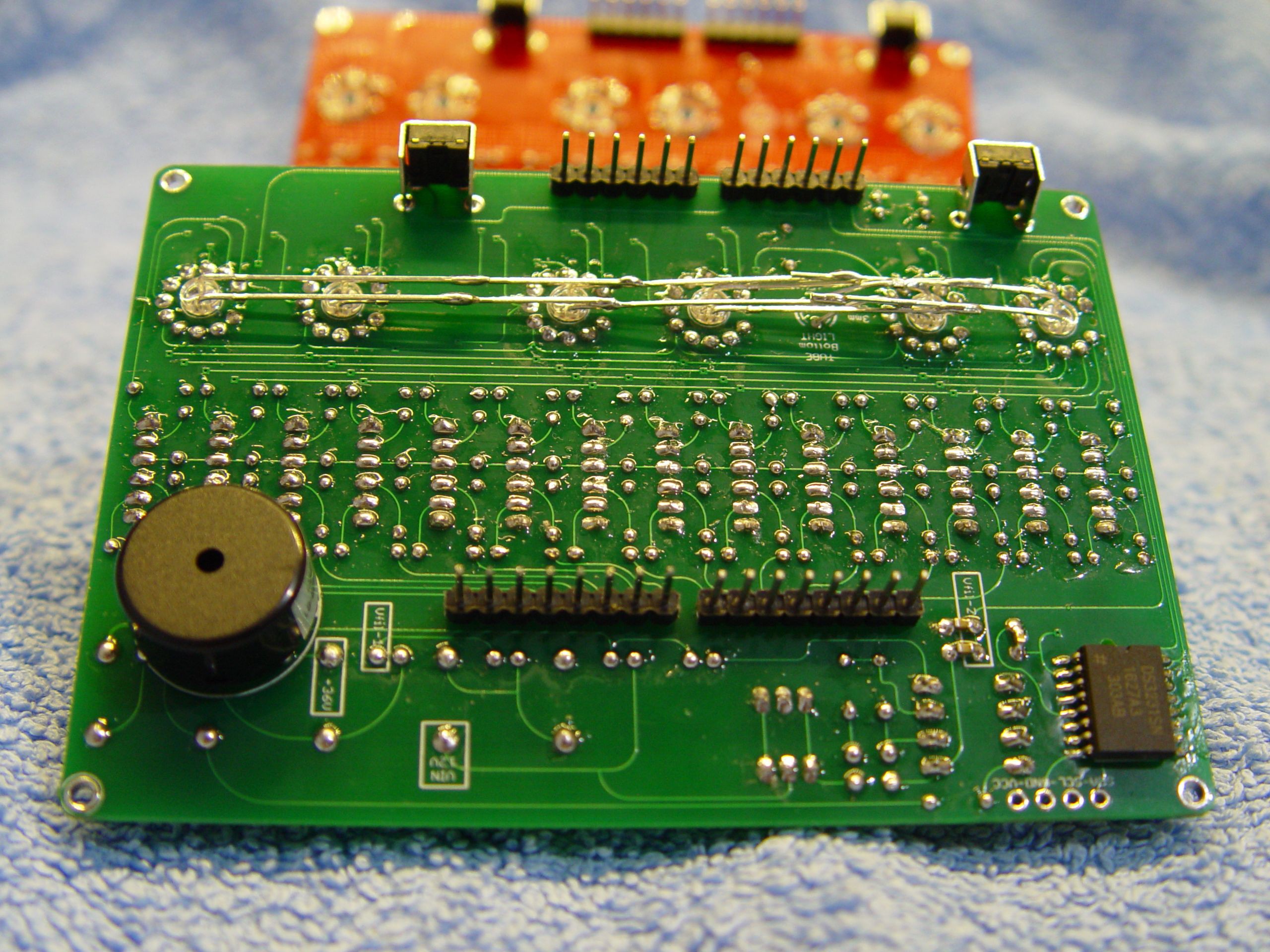
- hand painted curved traces for more retro look
- all outputs are marked on pcb for better debugging
- schematic is almost unchanged, some pins are swapped for better PCB routing
I created simple CLOCK arduino sketch (firmware)

- IV-3
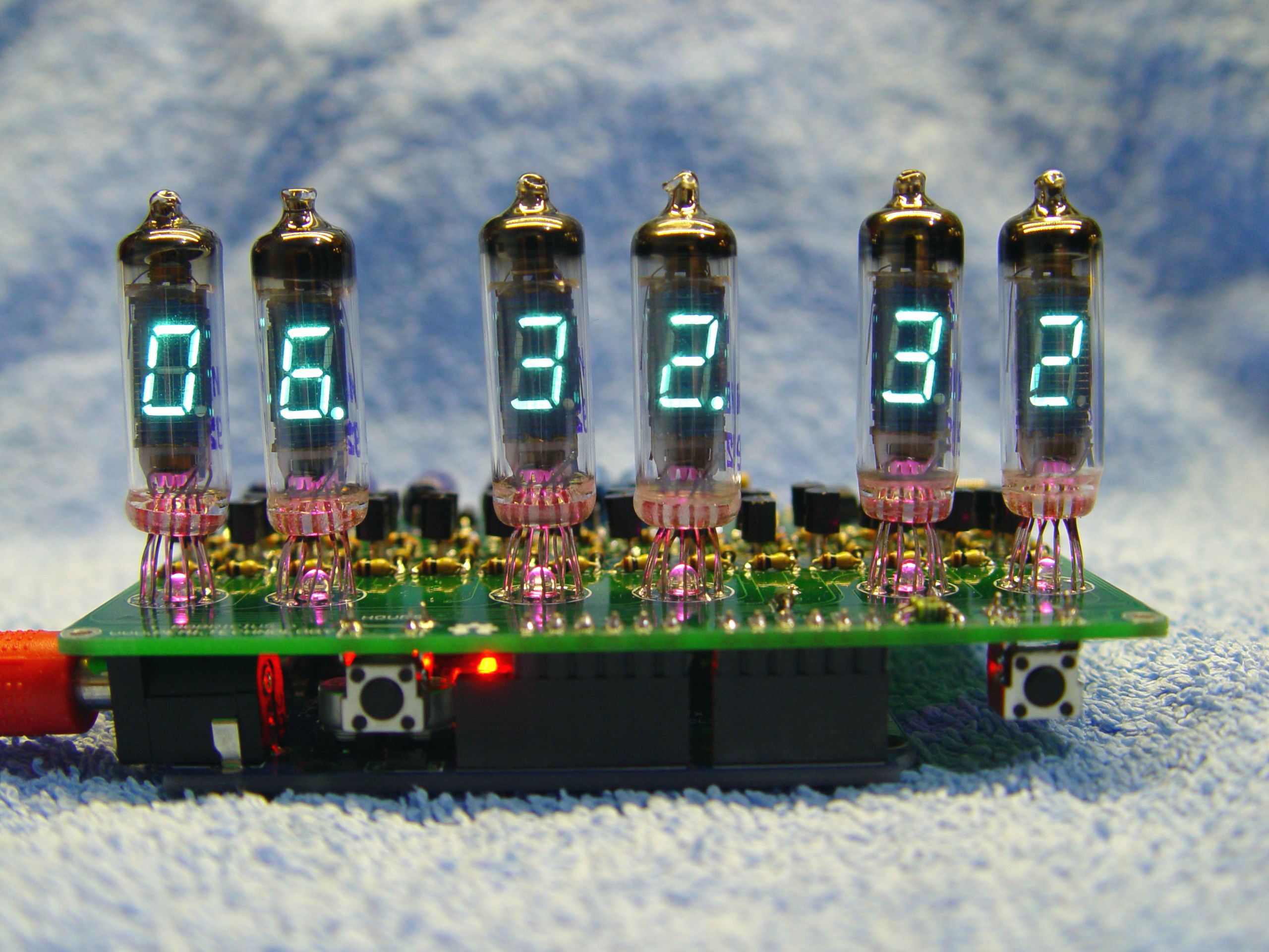
- IV-6
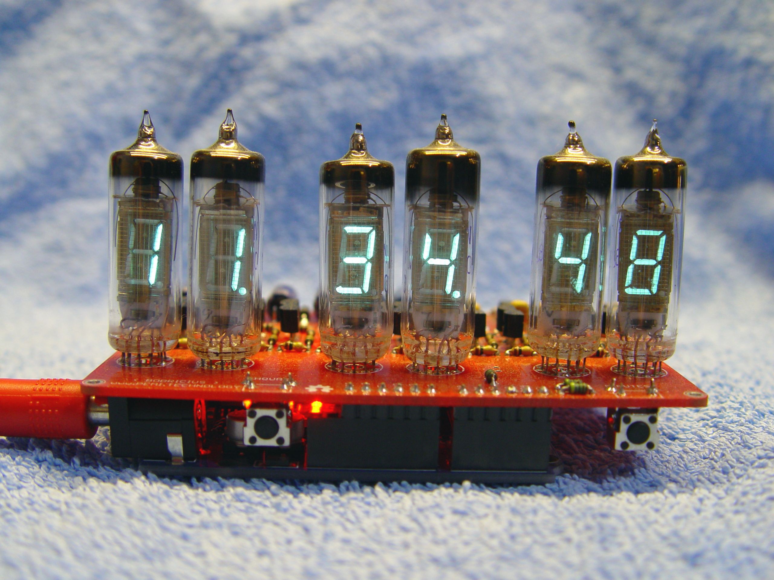
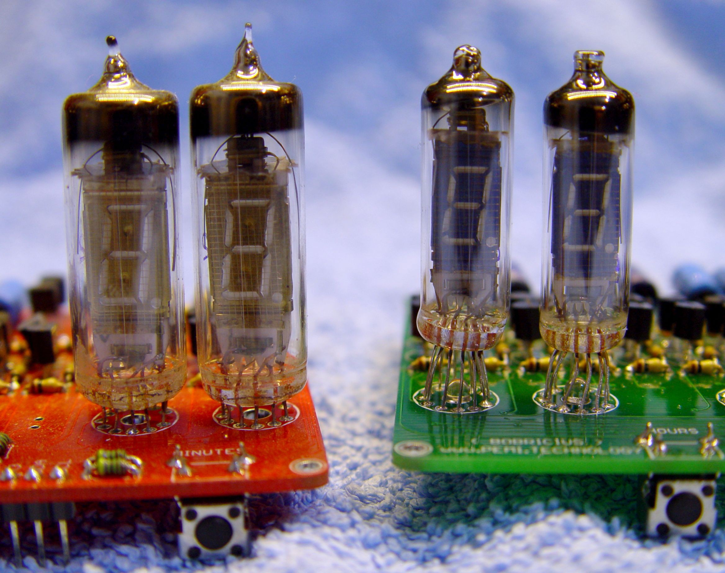
- IV-3 vs IV-6
- Backlit just parallel connected LED

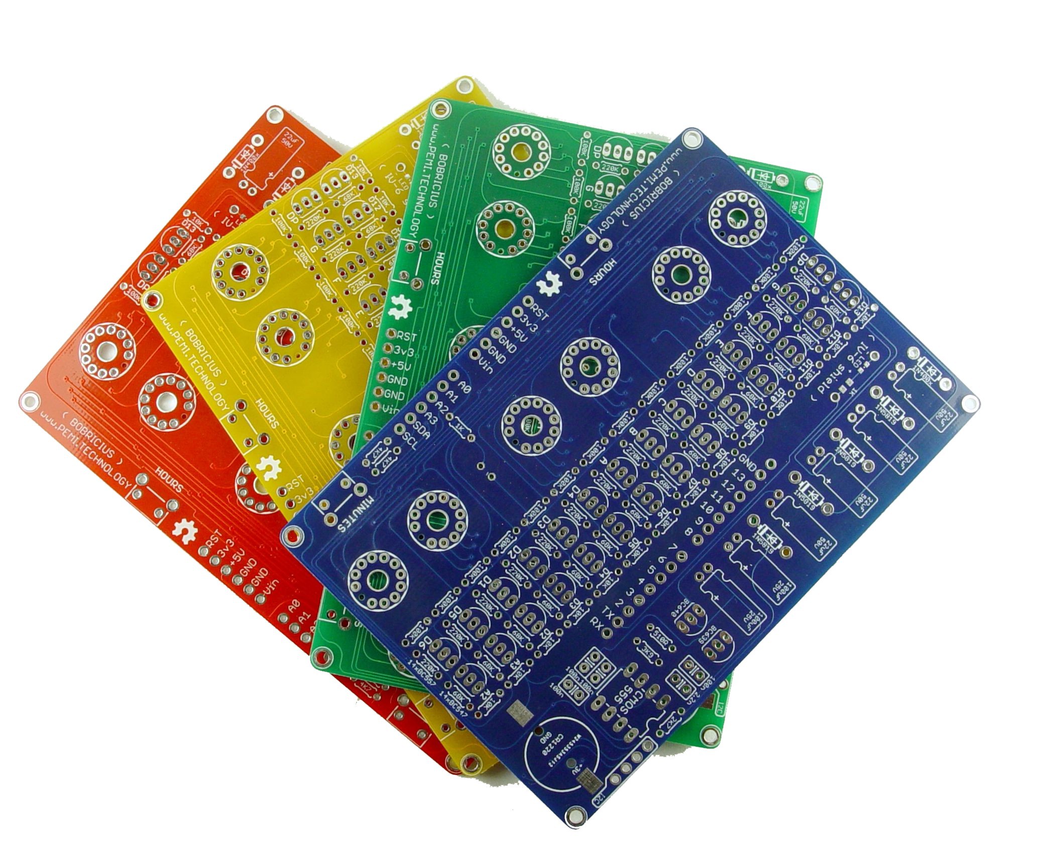
Large batch PCB ORDER LINK http://dirtypcbs.com/store/designer/browse/bobricius
Required parts list IV‐3/IV-3a/IV-6 shield for Arduino (BOM )
- 1/4W subminiature carbon THT resistors
| Pcs | value | Description |
|---|---|---|
| 1 | 510 Ω | Ø1.8x3.2mm |
| 2 | 1K | Ø1.8x3.2mm , tube light, optional |
| 1 | 2K7 | Ø1.8x3.2mm |
| 1 | 3K9 | Ø1.8x3.2mm |
| 14 | 10K | Ø1.8x3.2mm |
| 14 | 68K | Ø1.8x3.2mm |
| 14 | 100K | Ø1.8x3.2mm |
| 14 | 220K | Ø1.8x3.2mm |
- CERAMIC/MKT /MKM CAPACITORS
| Pcs | value | Description |
|---|---|---|
| 1 | 2.2 nF | - |
| 1 | 100 nF | - |
| 2 | 8.2 nF !!! | I am replaced with 100nF |
- ELECTROLYTIC CAPACITORS
| Pcs | value | Description |
|---|---|---|
| 4 | 22 µF 50V | - |
| 2 | 100 µF 25V | - |
- DISCRETE SEMICONDUCTORS
| Pcs | value | Description |
|---|---|---|
| 1 | 1N400x | rectifier diode |
| 4 | 1N5819 | schottky diode |
| 6 | LED 3mm | Tube bottom light optional (choose color freely) , optional |
| 14 | BC547B | NPN transistor |
| 14 | BC557B | PNP transistor |
| 1 | BC639 | NPN “power” transistor |
| 1 | BC640 | PNP “power” transistor |
- INTEGRATED CIRCUITS
| Pcs | value | Description |
|---|---|---|
| 1 | ICM7555 | timer IC (must be CMOS version, do not use a standard 555 !) |
| 1 | DS3231 | RTC chip , optional |
- CONNECTORS & OTHER PARTS
| Pcs | value | Description |
|---|---|---|
| 1 | Arduino UNO | or clone |
| 28 | header | spacing 2.54 mm |
| 1 | CR1220 | Lithium battery , optional |
| 1 | CR1220 socket | Battery holder , optional |
| 6 | tube | IV‐3/IV-3a/IV-6 VFD tube |
| 2 | switch | angled, Microswitch TACT |
| 1 | Piezo 17mm | buzzer, optional |
If you want original board go here >
https://www.elektor.com/iv-3-vfd-shield-for-arduino-kit-150064-71
https://www.axiris.eu/en/index.php/project-corner/iv-3-shield-for-arduino


 Alex
Alex
 OzQube
 ElectroBoy
 Discrete Electronics Guy
Six month than my clock is working 24/7.
The only issue I got was a short circuit with the USB connector housing, I burnt one transistor. replaced easily. I removed the metal shield of the USB plug.
Could a wifi+ntp version could work with the Arduino Uno R4 wifi ?
There is 3 weeks of delay, but I could compile the original sketch without any errors or warning...