Charger & protector selection
A TP4056 charger & battery monitor module exists, but it takes up too much space. So we'll implement it ourselves. Some similar projects have been done:
- DIY LiPo Charge/Protect/5V Boost Circuit
- #160 40 Cent Do-It-Yourself Li-Ion Protectors for 18650 Cells (Tutorial) and how they work
Charger
The TP4056 has a big package. Other charger IC's are available on digikey (MCP73831, bq21040, STC4054).
- The
STC4054has the highest leakage current when no power supply attached. - The
MCP73831only accepts maximum 6V, while the TP4056 breaks at 8V input. - The bq21040 seems the best deal. It provides max. 800mA instead of the 1A on the TP4056. It's 20 times more expensive than the TP4056, but it won't be killed by an input voltage up to 30V.
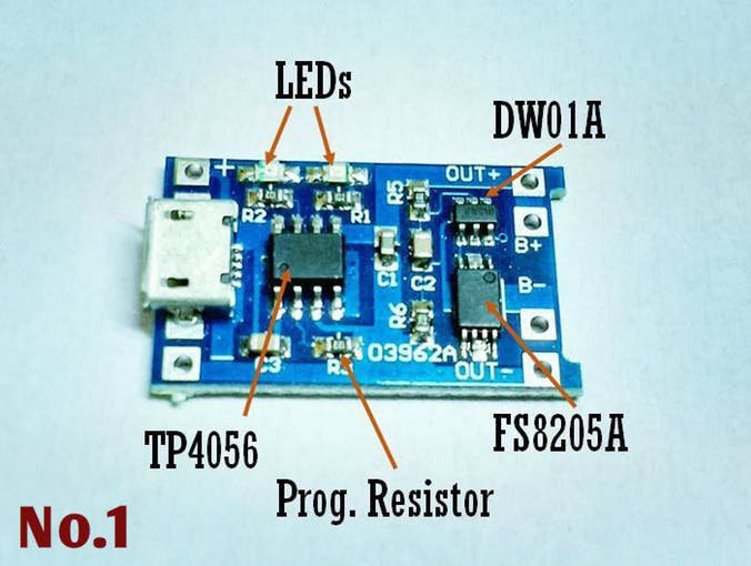
TP4056 module
- TP4056 module GREAT WALL Electronics Co., Ltd., €0.28
- TP4056 datasheet
- TP4056 Micro-USB Battery Charger Circuit Diagram
- 1A charge current, set by R3
- Implements charge termination, as continuously trickle charging a Li-Ion-cell should be avoided.
- When VIN < Vbat, the module will only discharge the battery with a 3.7µA current. 3µA of it is due to the battery protection IC.
- Battery protection IC. The undervoltage lockout (UVLO) is an important parameter. When discharging a Li Ion with a 1A or smaller current, the battery has already lost 90% of its energy when the battery voltage drops below 3.3V.
- Fortune DW01A battery protection IC. Alternative battery protection ICs such as the AP9101C also require about 3µA.
- UVLO = 2.4V (Do not use this chip!), It's not recommended to discharge a Li-Ion-cell so deep.
- AP9101CAK6-family is pin compatible.
- Fortune DW01A battery protection IC. Alternative battery protection ICs such as the AP9101C also require about 3µA.
- Contains dual NMOS
- by default FS8205
- replacement part DMG9926UDM
- Automatic charge termination
- Can be directly connected to a solar cell (#155 The 5 Best Solar ChargerBoards for Arduino and ESP8266)
- pin 7: ON = charging (LED closest to USB connector) pin 6: ON = charging finished

A power switch (such as this PMOS) is needed because the LiPo can't be charged while being connected to the load. The explanation lies in the charging algorithm. Suppose the voltage of the LiPo has dropped below 3V3, then the TP4056 will only allow 60mA on its output. If a load is connected that draws more than 60mA there will be no current left to charge the LiPo. The LiPo will remain discharged forever (or until the load is disconnected). More info can be found here.
The efficiency can be improved by replacing the schottky diode by an NMOS, switched by an NPN-transistor. The base of the NPN-transistor is connected to 5V through a voltage divider.
Battery protector
Charging a battery is one thing, protecting it from over-, under voltage, over current is another thing. The TP4056 module includes a DW01A protection IC and a double N-MOSFET: FS8205A.

More info about this module can be found here.
The DW01A has a too low UVLO limit, so we'll replace it by the AP9101CAK6-ANTRG1. The MOSFET's TSSOP8 package might not be so easy to solder. The DMG9926UDM will be used instead. You could also use the FS8205, which is actually the same as the FS8205A except for the package.
The over-current protection can be set by using the AP9101Cxxx-ANTRG1 or the BV-variant. A factor two in current increase can be gained by putting several MOSFETs in parallel as done here.
 Christoph Tack
Discussions
Become a Hackaday.io Member
Create an account to leave a comment. Already have an account? Log In.