Over voltage protection section
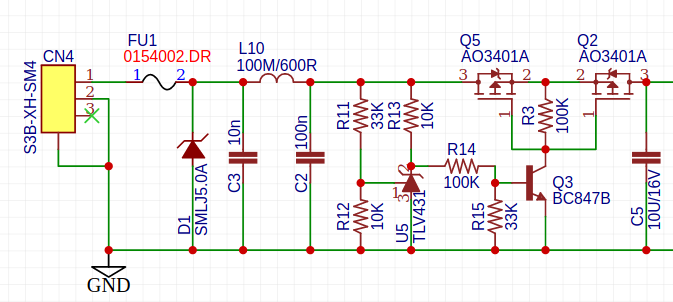
The peak voltage over D1 is 9.2V, this would destroy U2. To prevent this, an extra over voltage protection using U5 as voltage detection element and Q2 and Q5 as switching elements.
Q2 and Q5 switch off when the input voltage rises higher than 5.28V.
Applying 24VDC causes D1 to conduct, which trips the fuse FU1. This is ok.
To check if the circuit around Q2, Q5 works well, a voltage of 6.5V has been applied. This is low enough to prevent D1 from conducting, but high enough to turn of Q5.
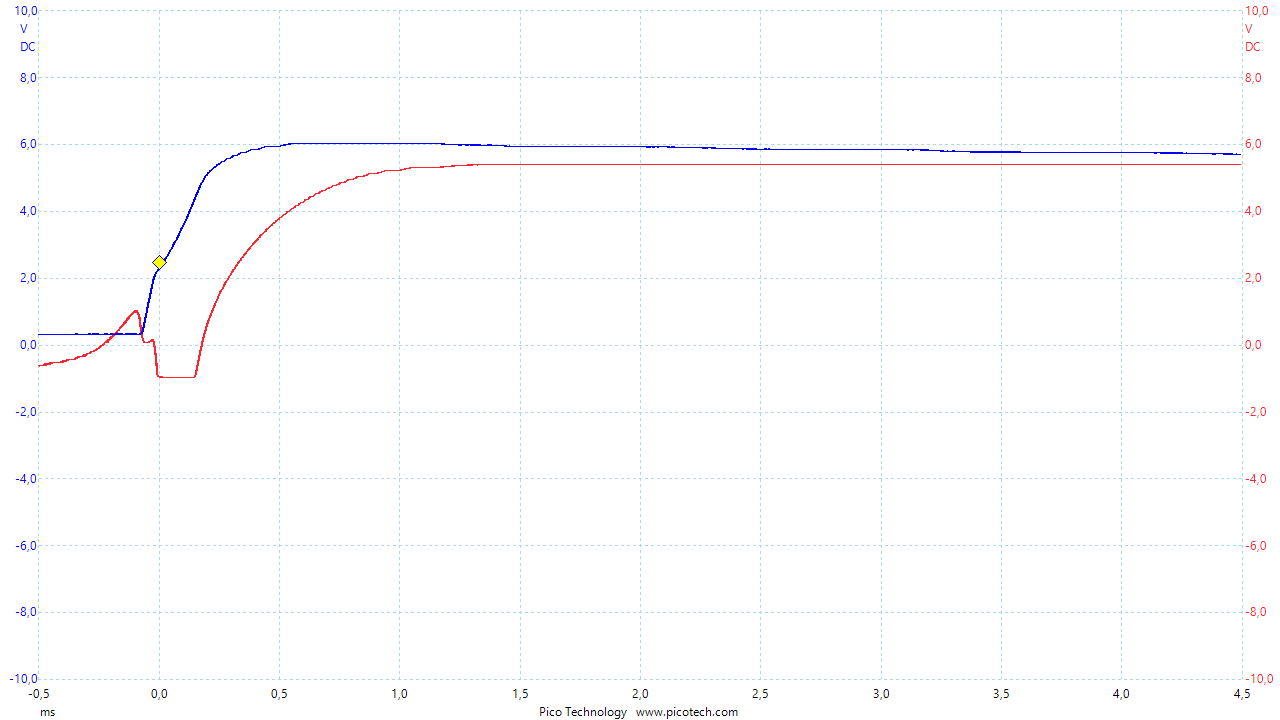
There's clearly something wrong with this design. Low voltage turn-on is quick due to U5 that starts conducting, but turn off of Q2 and Q5 is too slow. This results in the voltage on C5 rising above the designated 5.28V.
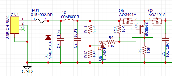
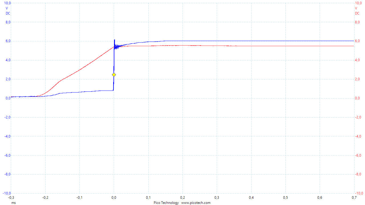
Decreasing R3 will speed up the discharge, but this design is inherently flawed. Turning of Q2 and Q5 should be lightning fast to prevent damage to U6.
Solving the problem
Charging section
Charge current is set to KISET / RISET = 540 / 1K = 540mA.
The Li-Ion cells I used were at the end of their lifespan, but they Initial constant current charging happens at 430mA.
The red LED is on during charging. After the charging process is completed, the LED turns off;
Lithium Ion protection section
After insertion of a Lithium Ion battery, briefly connect it to the charger. This is needed to take the protection-IC out of Power-Down mode.
Although I ordered the AP9101CAK6-ANTRG1 from Digikey, the auto-wake-up functionality, designated by the A, doesn't work. After battery insertion, charger connection is needed.
Over voltage
- Measured : 4.25V
- Datasheet AP9101Cxxx-ANTRG1 : 4.225V
In case of over voltages, the CO-pin will go low. Remark that this doesn't fully disconnect the battery from the load. Discharging the battery is still possible. A load connected to the battery will still be able to draw current from the battery. The current will flow through the channel of the FET controlled by the DO-pin. This FET is still conducting. The current then follows its path through the body diode of the other FET, which is off.
This is a useful feature, as it allows the battery to return to a safer state.
In case of over voltage (most likely to be caused by over charging), when CO-pin is low, charging is no longer possible.
Under voltage
- Measured : 3.22V
- Datasheet AP9101Cxxx-ANTRG1 : 3.20V
In case of an under-voltage-event, the DO-pin will go low.
Over charge current
todo
Over discharge current
The circuitry has been connected to an electronic load. Using the DMG9926UDM-7, the maximum current was 1.35A. This is mainly because the AP9101Cxxx-ANTRG1 has a VDOC of only 60mV. Replacing the battery protection IC by the BV-variant, would increase the maximum discharge current to 2.25A.
3V3 buck regulator
Efficiency measurement
An electronic load has been used as load on the 3V3. The board was powered using the thin wires from the JST-XH leads.
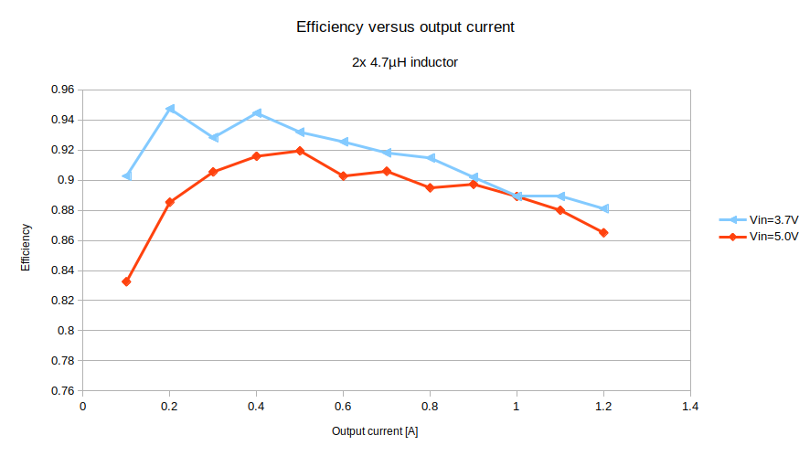
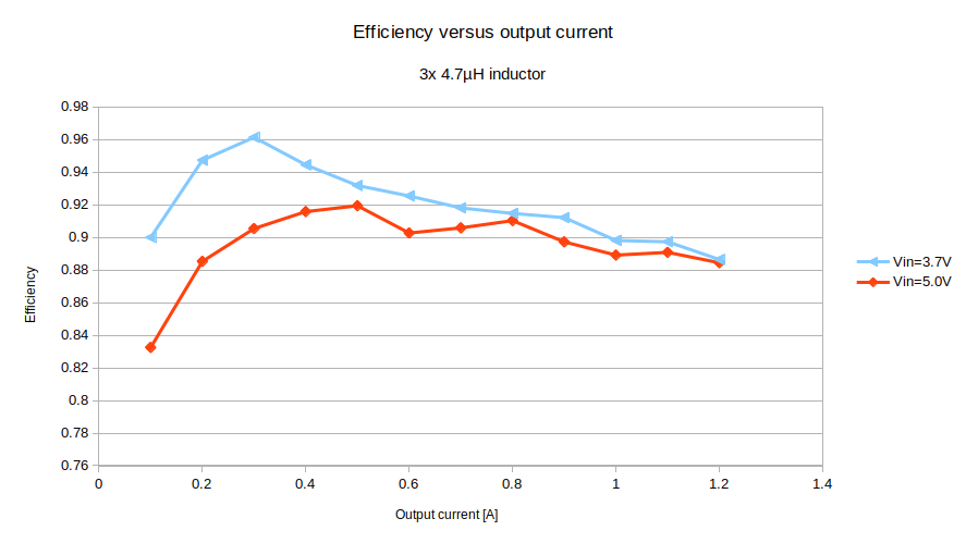
Remark that if we had used an LDO instead of this buck regulator, we would have had 90% efficiency (theoretical maximum) for 3.7V input and only 66% efficiency (theoretical maximum) for 5.0V input.
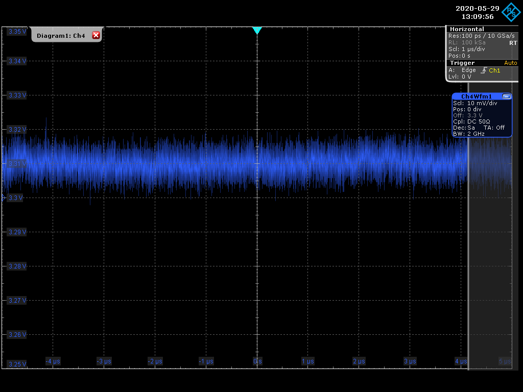
Ripple measurement
For that we apply a 500mA load and power the board with 5V.
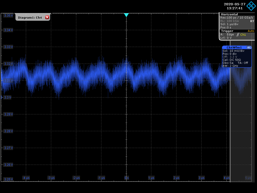
It seems like there's a considerable amount of ripple. Let's see if we can do better.
 Christoph Tack
Discussions
Become a Hackaday.io Member
Create an account to leave a comment. Already have an account? Log In.