 Grant Giesbrecht
-
1Identifying the problem
The exact issue I fixed was that the machine would not boot. When I turned it on, the fan would come on, but the screen stayed black. I had seen this before in the past, but simply power cycling it would solve the problem. After about a year of dealing with this whenever it came up just by restarting the machine, it completely died and power cycling wasn't able to help.
I opened up the generator's case and started probing power rails. This was made easier because Dave Jones over on the EEVBlog has done both a teardown and a repair of this series of generator, although the problem he repaired was different from what I encountered.
Dave Jones's Videos:
My unit's problem was the 5V supply on the board with the applications processor. The supply was outputting almost exactly 2.5V. It was easy to verify that this really was my problem because in Dave's "Siglent Signal Generator FAIL" video at 5 min 25 sec he probes the exact same rail and saw 5V. Additionally, his same video shows a power LED illuminated by the TI processor that was not turning on for me.
-
2Looking for the cause of the 5V rail failure
I traced back the 5V test point to figure out where it was being generated. I found it was coming from a switch mode power supply that was being power from the 6.5V input to the main board. A quick search of the controller's part number (TPS5430) gave me the datasheet and application examples. It turns out, Siglent used almost exactly the circuit from the example.
![]()
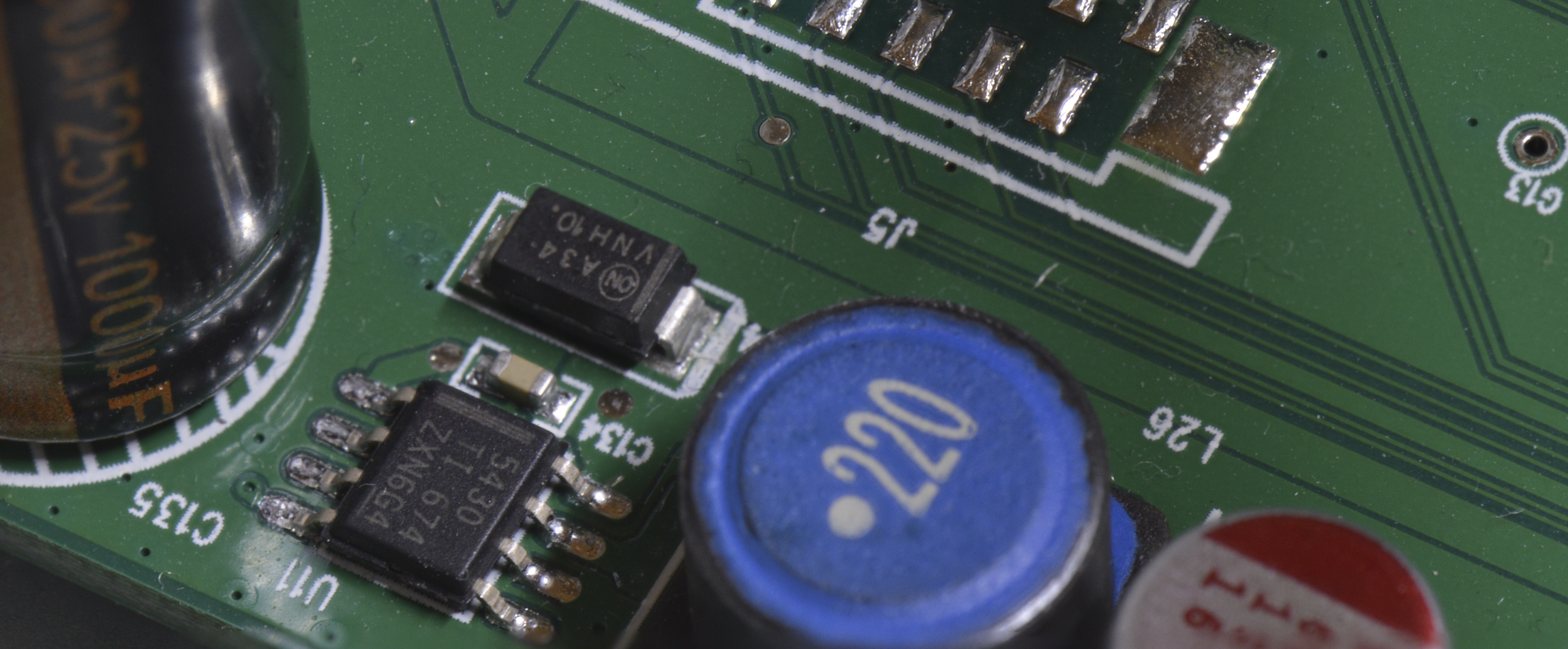
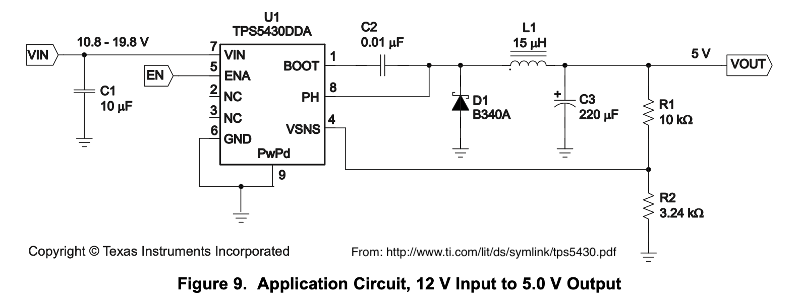
The step-down converter IC, diode, inductor, and output capacitor used in the 5V supply. ![]()
Example circuit taken from the converter IC's data sheet. Some values were changed, but otherwise the circuits are nearly identical. I probed each of the IC's pins to try to track down the problem. I got stuck when everything looked right except for the output voltage and the level from the feedback network. Vsense expects 1.22V from the feedback network when at the correct output voltage. I saw .63V, almost exactly half of 1.22V.
I checked every component to make sure it's listed value matched what I measured, and I couldn't find any problems. Although sometimes I saw readings that missed the mark and attributed it to other components in the circuit, but nothing stood out as fried. Additionally, everything looked fine visually.
-
3Repairing the supply
At this point I was slowing down because I couldn't find anything that needed to be fixed in the 5V supply. So before I tried anything risky which might break stuff I emailed Siglent to see if they could sell me a new main board or how much they would charge to repair it. They quoted $340 for parts, labor and shipping. A new generator costs barely $100 more than the repair cost, making Siglent's repair option seem pretty bad. They offered me 5% off a new generator, but Amazon already undercuts their MSRP by more than that.
The other option I saw was to hook up my bench power supply to the 5V rail and see if I could get the generator to boot. I thought the step-down converter's feedback network would constantly give the correct 1.22V 'okay' signal to the converter IC's Vsense pin, preventing the IC from trying to fight my bench power supply. The Siglent service manual quoted a 5% tolerance on the 5V rail, and my Rigol DP832 can of course operate within way tighter tolerances. I set a current limit of a few hundred mA, set the ouput to 5V and turned on my waveform generator with this external 5V supply. I was very happy to see it boot up happily and work flawlessly :)
To make this a permanent solution, I soldered a LD50V low-dropout regulator onto a PCB with decoupling capacitors on the input and output. I used 100nF at the input and 10uF at the output, per the datasheet's recommendation.
To wire my board into the generator, I soldered a strip of male headers onto the main board where I probed the 5V rail. In addition to the 5V test point, this strip also had a ground connection. To provide power to my 5V supply, I piggybacked off of the wire proving 6.5V to the main board. The connector was semi-exposed and I was able to jam my wire into the same connector as the main board used. Although I intended to use the ground connection in the strip of header pins with the 5V test point, I had to use the chassis ground point instead because somewhere along the line I broke the pad on that ground pin. I think when I pushed the ground wire onto the header I applied too much force and tore it off. This shocked me because I was pretty gentle - I think the pad was just really fragile and not expecting clumsy ape-hands to be messing with it.
Here are photos of the patch board and how I connected it into the generator:
![]()
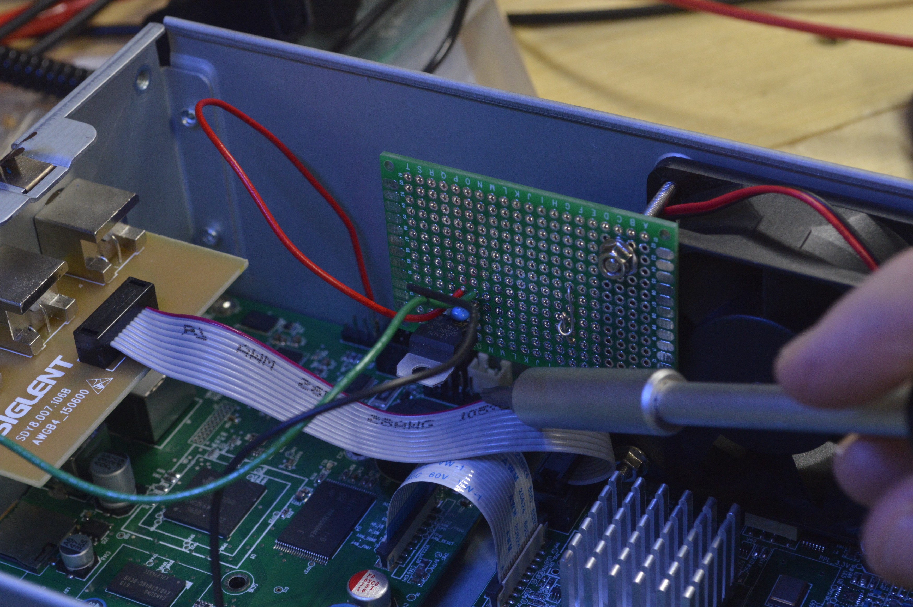
My new 5V supply board inside the chassis. I used one of the fan's mounting bolts to hold it up, and a loop of hookup wire pressing against the fan to keep it from rotating. ![]()
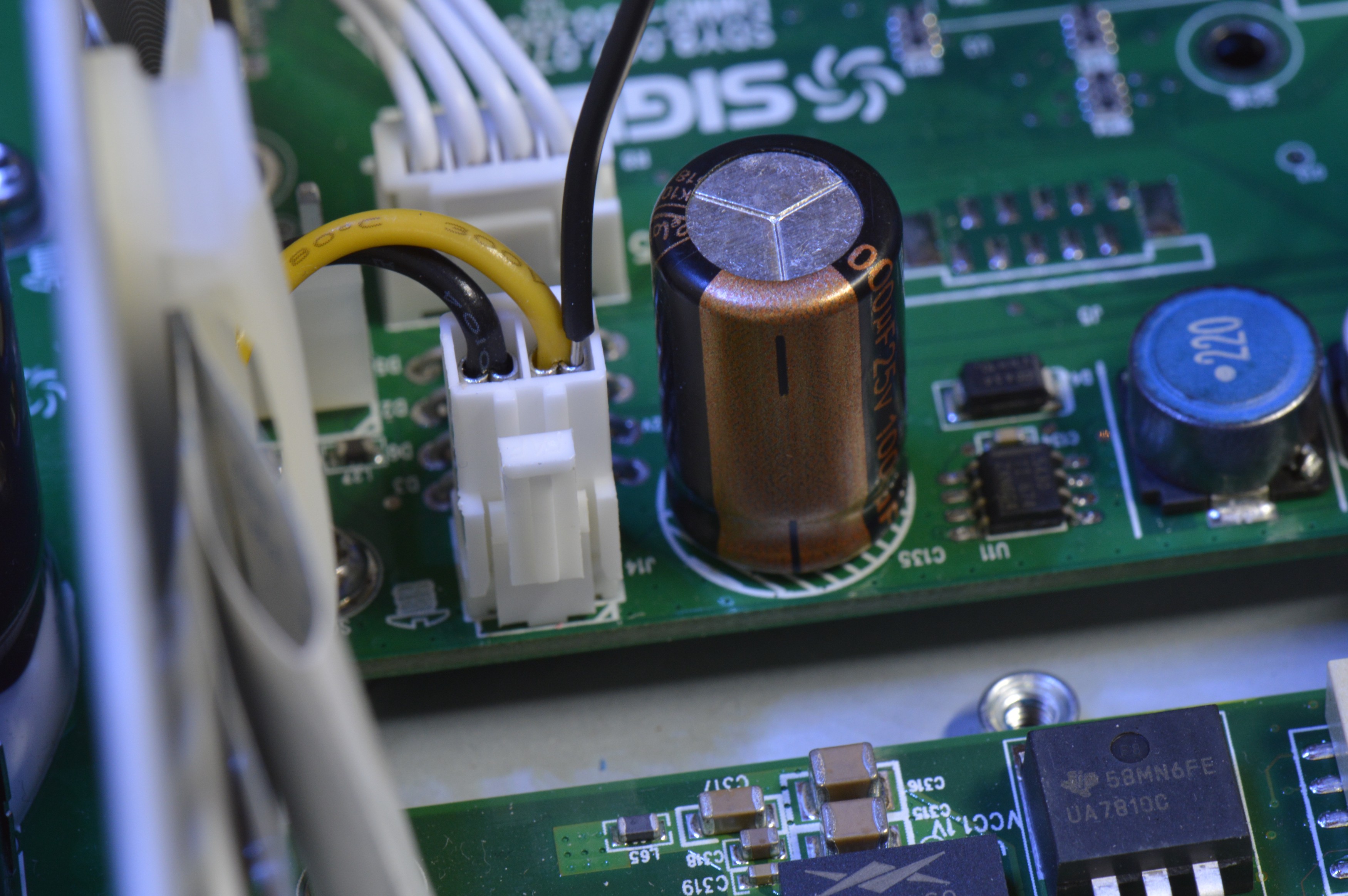
Here's my 5V connection. You can see the male header pins I added. I used a dupont connector on the 5V cable to connect to the header pins.
![]()
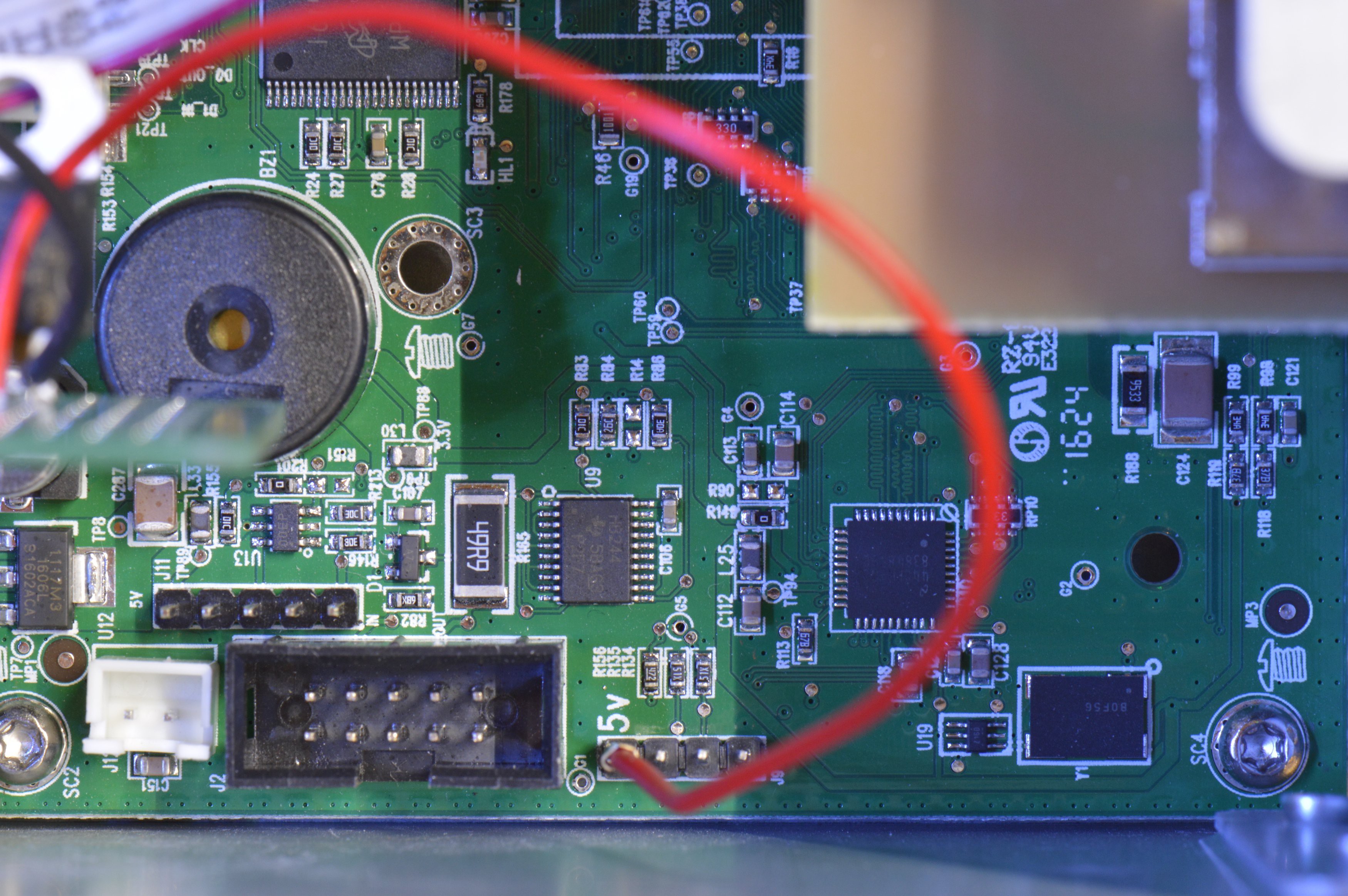
The black wire on the right is the power input for my repair board. Admittedly, it's a pretty precarious solution to just sneak my wire into the crimped connector, but hey - it works! ![]()
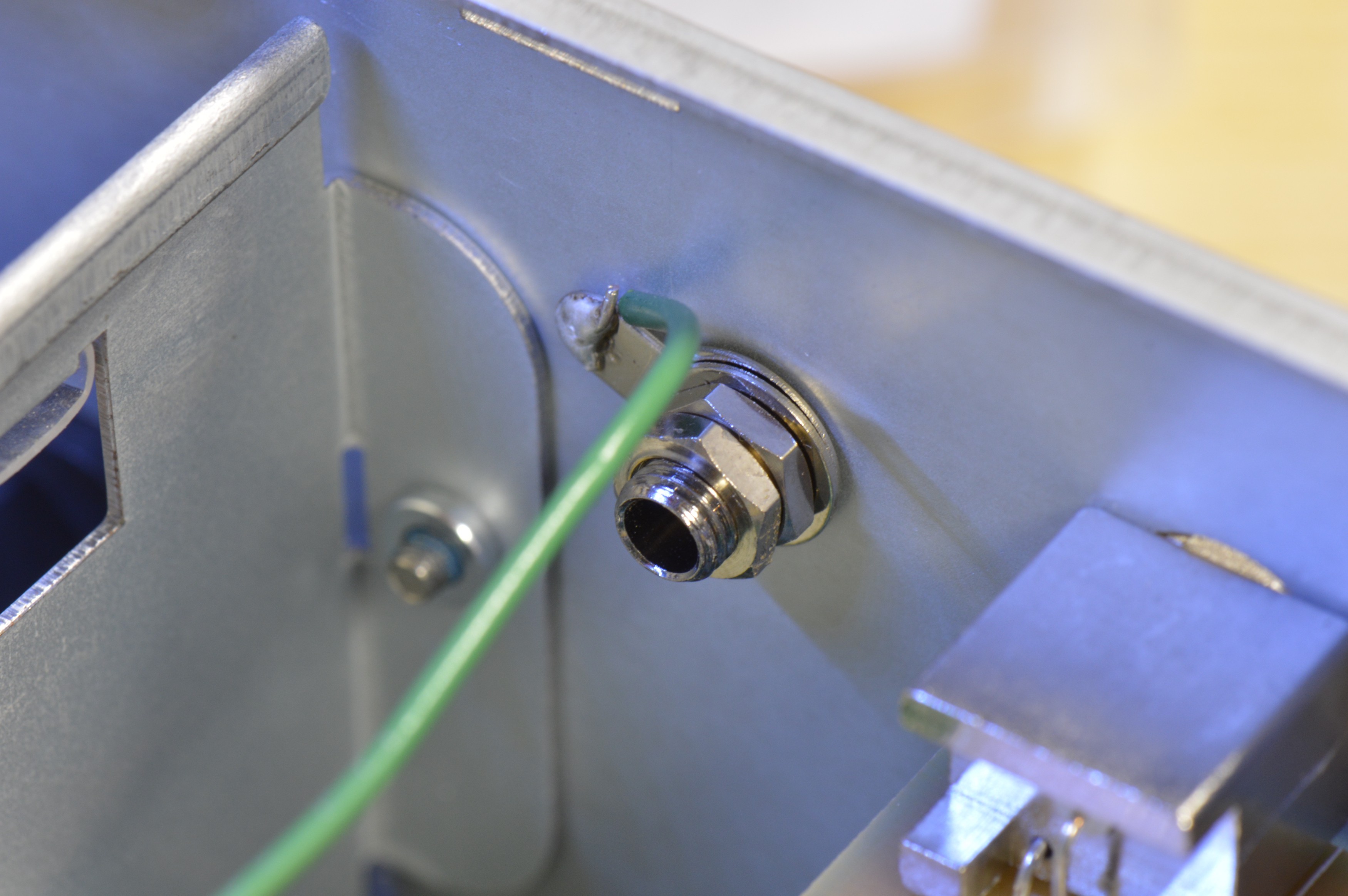
This one is pretty straightforward. The chassis ground and main board's ground were connected so I was able to connect to the chassis nice and beefy ground connection. I powered up my generator with the new 5V supply and it worked great!
SDG2042X Repair
My waveform generator gave up the ghost, I fixed it with a homemade mod board
Discussions
Become a Hackaday.io Member
Create an account to leave a comment. Already have an account? Log In.