 Adam Lange
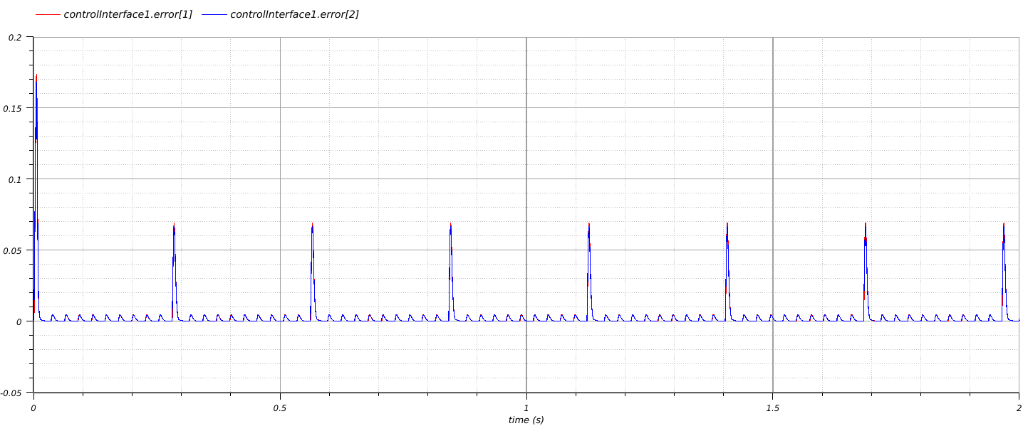
I created a modelica model that looks at the distance between the tool target and the actual position. Whenever the error is within a configurable tolerance the model records the current position of the machine joints and calls some external python code that reads new tool target positions from a file.
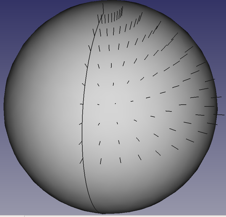
I created tool targets using pythonocc. I created a sphere. I accessed the position and normal vector of the sphere's surface at a few points and wrote those to a csv file in x,y,z,i,j,k format where x,y, and z are the position of the tool tip and i,j, k makes up a unit vector pointing from the tool tip back along the cutting tool axis. This is what the target points look like:
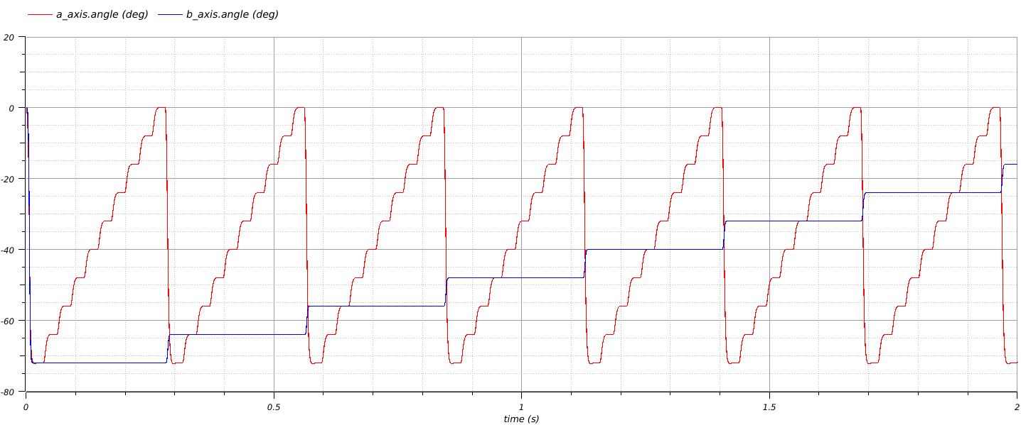
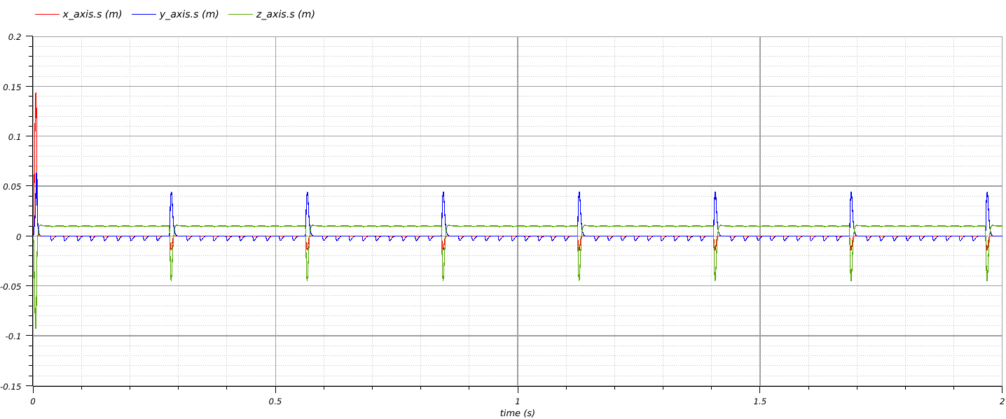
Here are the some plots of the modelica model running with the above tool targets:
The next part of the project will be to format the inverse kinematics solution into g-code so that I can run it on my milling machine and then to work on some routines for generating tool paths for milling.
Discussions
Become a Hackaday.io Member
Create an account to leave a comment. Already have an account? Log In.