-
13D printing
I created a spreadsheet of the times to print the parts for the basic flying saucer. This is the one I made without a NAS in it, that acts as a slave set of 84 LEDs to the first. It takes around 8 days to print (at 14 hours per day) or less when using a second printer for the smaller parts,
![]()
All-in the project uses 1.8KG of filament of various colours. The silver is used for the outer body parts, black is used for the main structural parts and as light separators. The white filament is used for the bottom 12-pixel-strip ring so as to reflect the light towards the centre of the 'cow abduction beam' . Transparent/clear filament is used for the diffuser parts.
You can download the STLs from thingiverse: https://www.thingiverse.com/thing:4113336
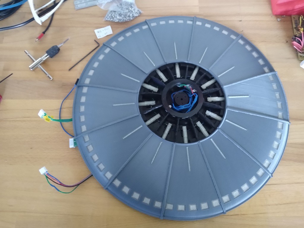
The silver body plates are printed as 12 separate parts, both top and bottom. They are printed in vertical orientation so that curved surface can be printed in a good resolution without the 'stepped' effect that the layer height otherwise gives.
All parts are printed with a 0.6mm nozzle and either 0.4mm layer height, which is about as high as I found to be reliably printable with a standard hot end on a CR10-S or S5, or 0.2mm layer height for those in the "fine print" column.
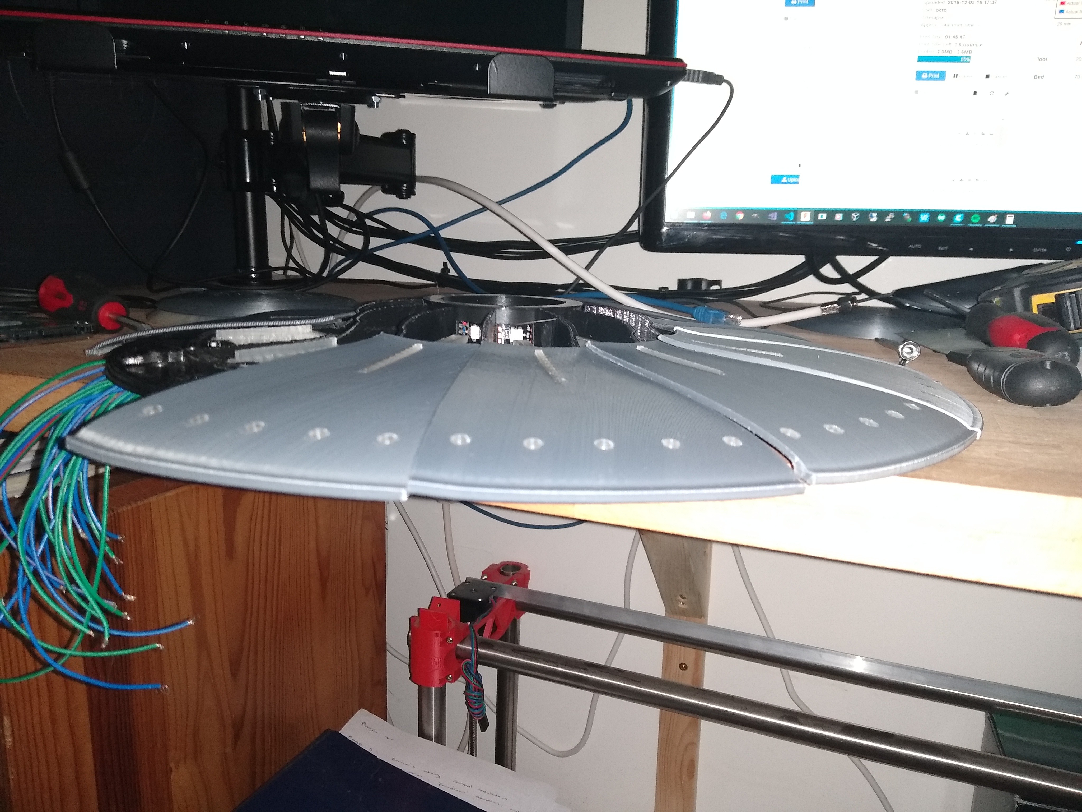
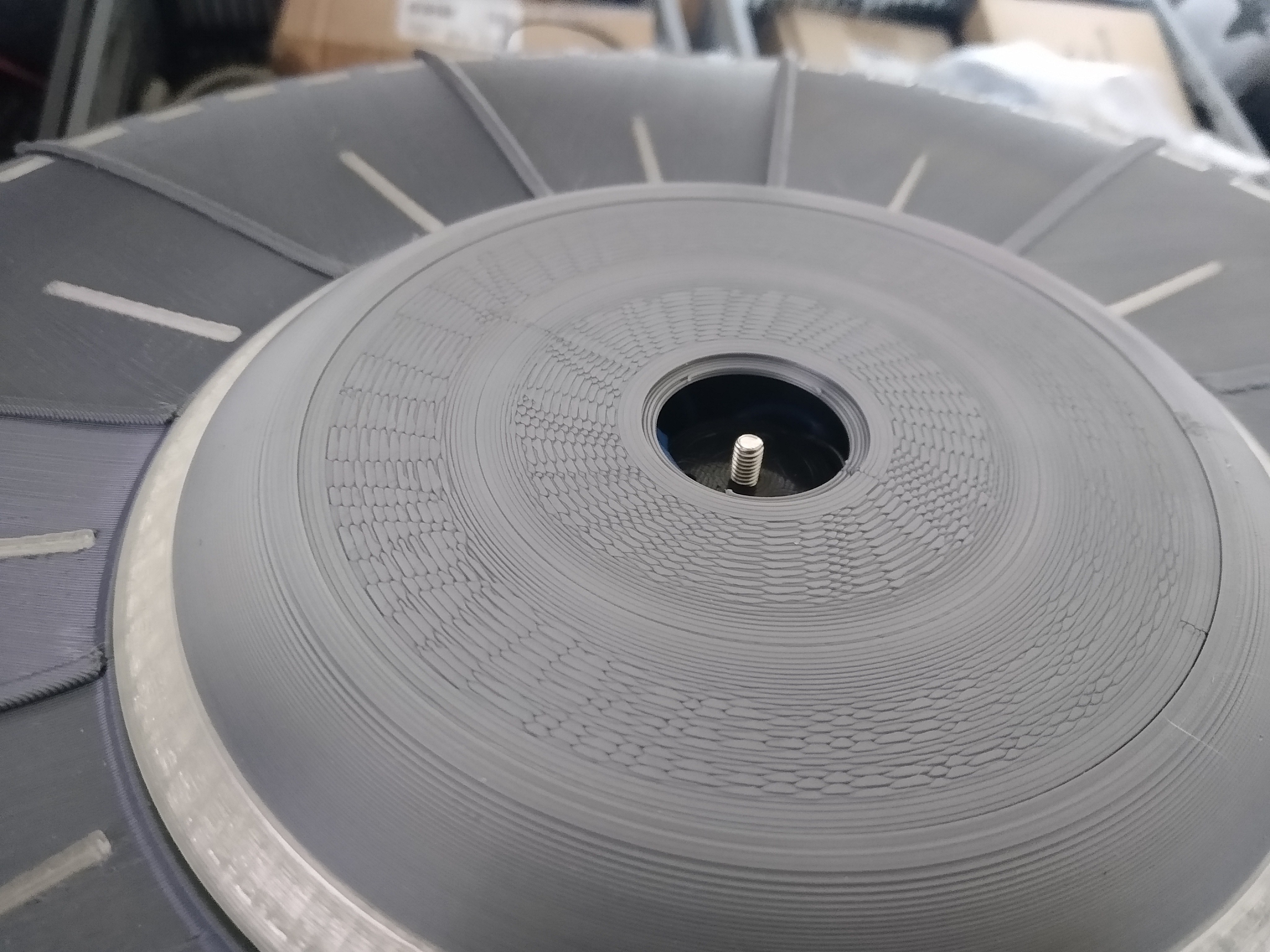
The top body plates are printed in sets of 4 around a central support pillar. I found this was necessary to avoid a strange warping effect that plagued my first set of body plates, which you can see in the image:
![]()
-
2Making the top
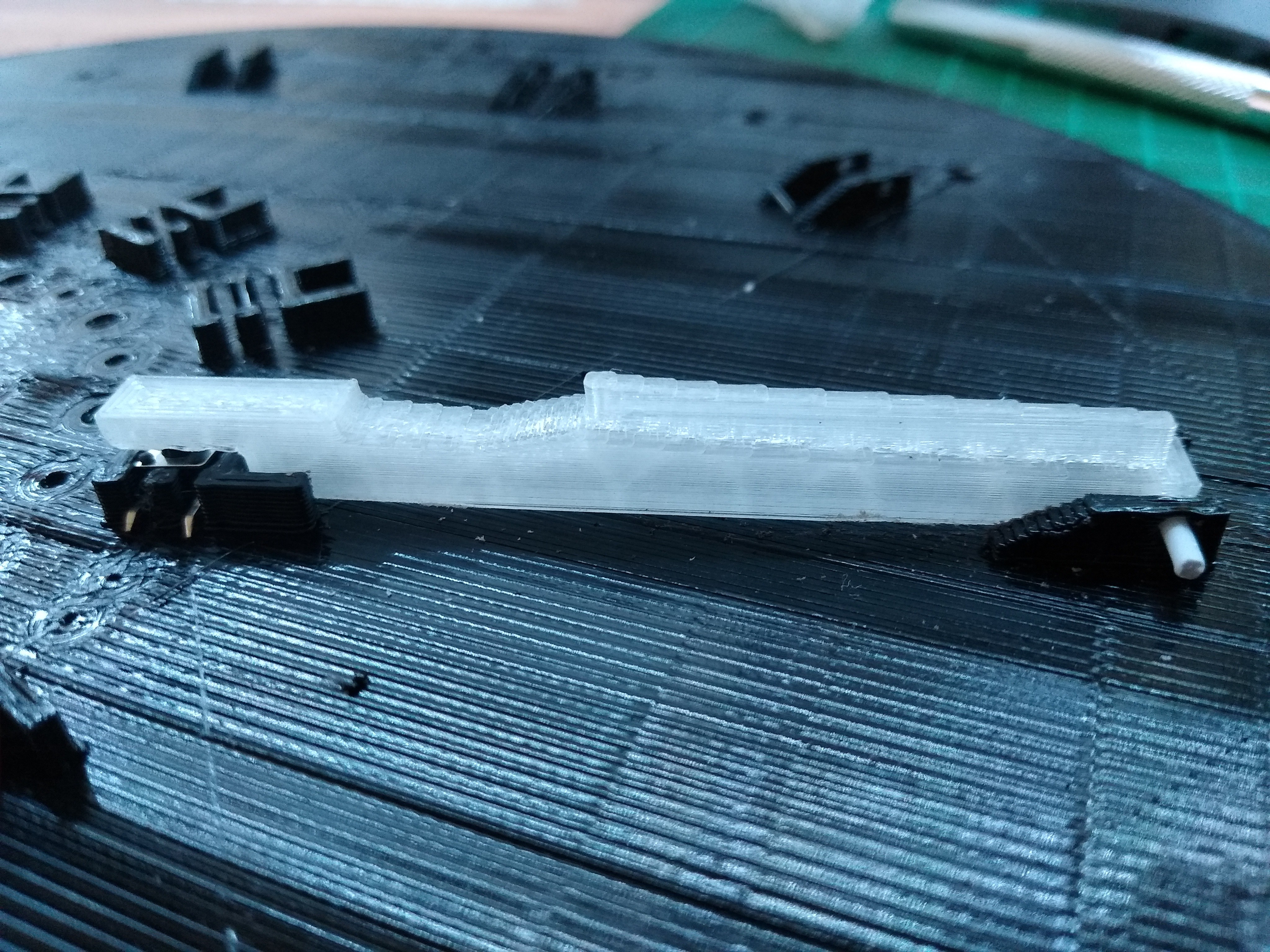
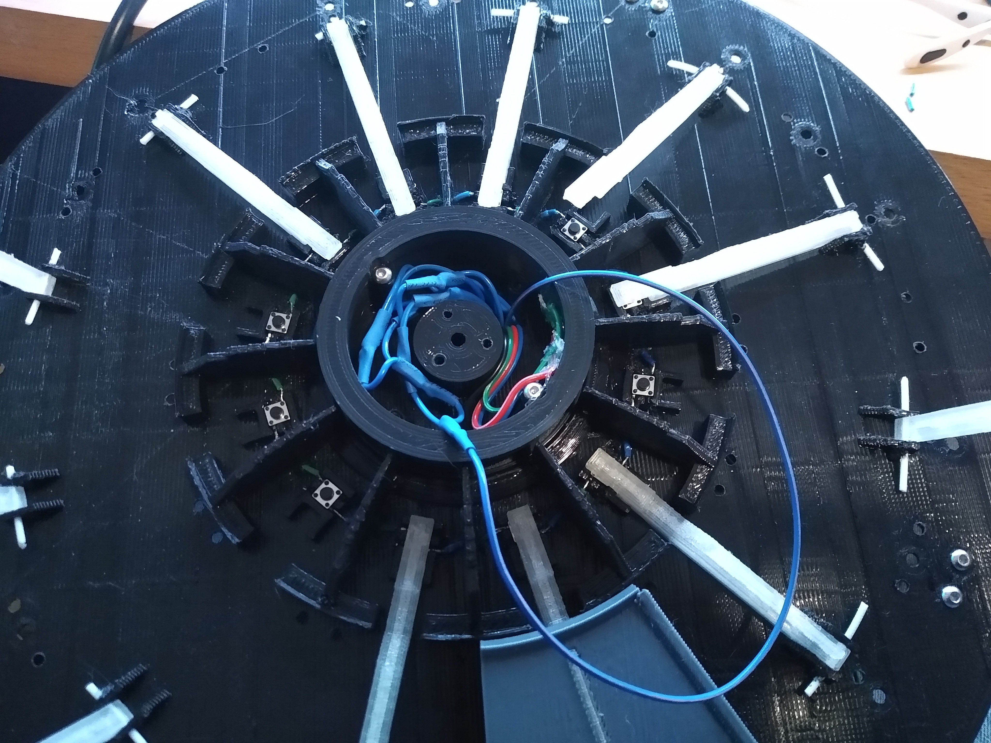
For the UFO containing the Raspberry Pi and other NAS components, small push buttons are added to the internal top plate. These buttons can be omitted for a 'slave' saucer that doesn't need these inputs. A transparent lever is added (in all cases) and a spare piece of 1.7mm filament is used to secure it. Repeat 12 times and solder wires to the buttons if used, enlarging the small holes with a drill if needs be to get the wires to the reverse side.
![]()
Wires come through like so:
![]()
After hot-gluing on the diffusers, the body plates are then attached to the support frame, which is in turn attached to the internal top plate, all using M3 screws.
This pic shows more of the construction:![]()
-
3Make the LED rings
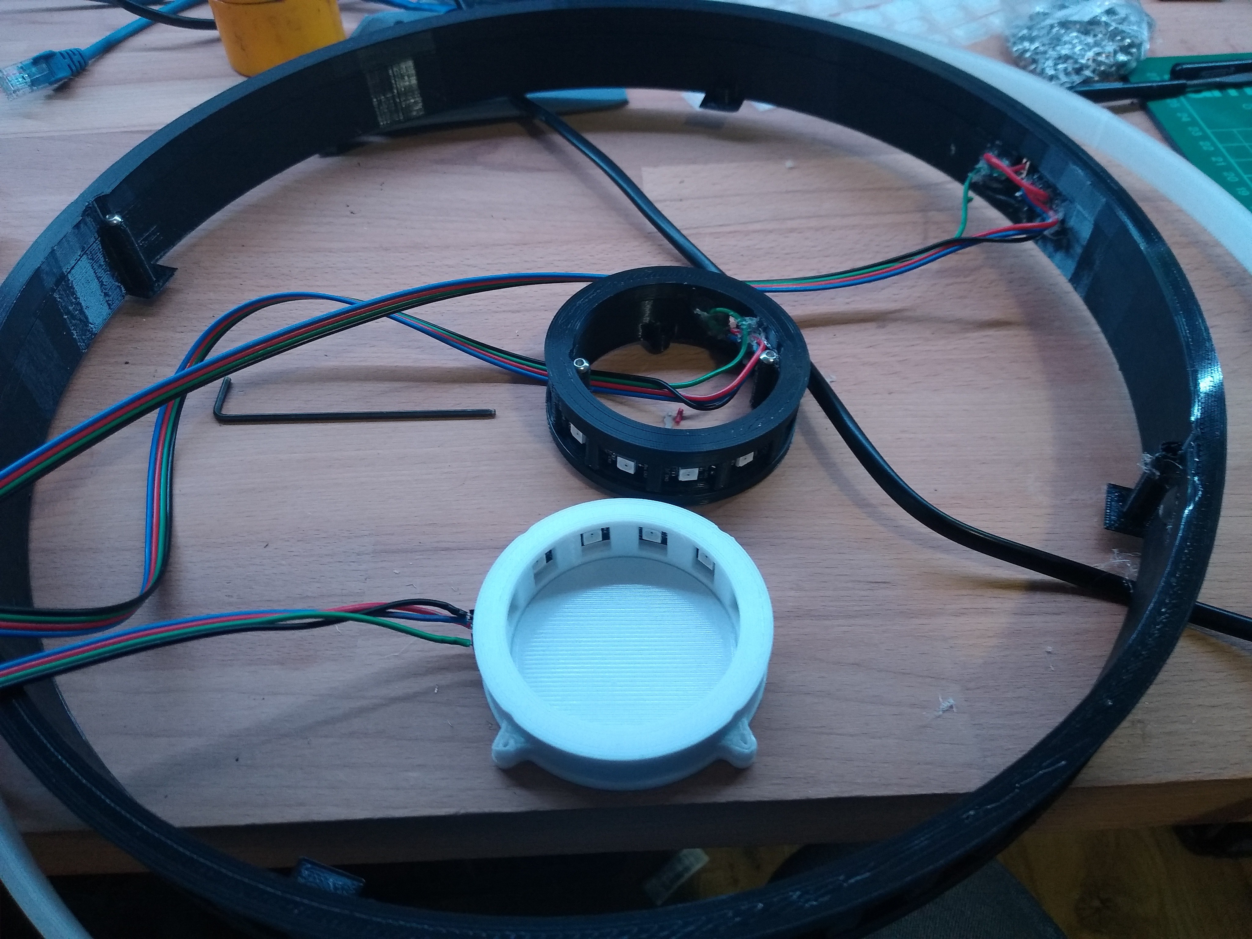
This is pretty straightforward now that the tolerances for the LED rings are generous. Two halfs of each ring sandwich a strip of 60 LEDs for the large outer ring and 12 LEDs for the top and bottom ring. A bit of soldering to the strips and hot glue later, you end up with a set of 3 rings that you can temporarily wire together and test with an Arduino running the example strandtest sketch.
![]()
M3 screws are used throughout almost all of this build.
-
4Wiring up
I used a set of 3 buck converters to provide 5V power from the 12V PSU that directly powers the HDDs. Each converter is rated at 3A, so one can drive the Pi, one to drive the big LED ring and one for the other two LED rings. Software limits the brightness of the outer ring since it could in theory need 3.6A at full brightness white (0.06A * 60).
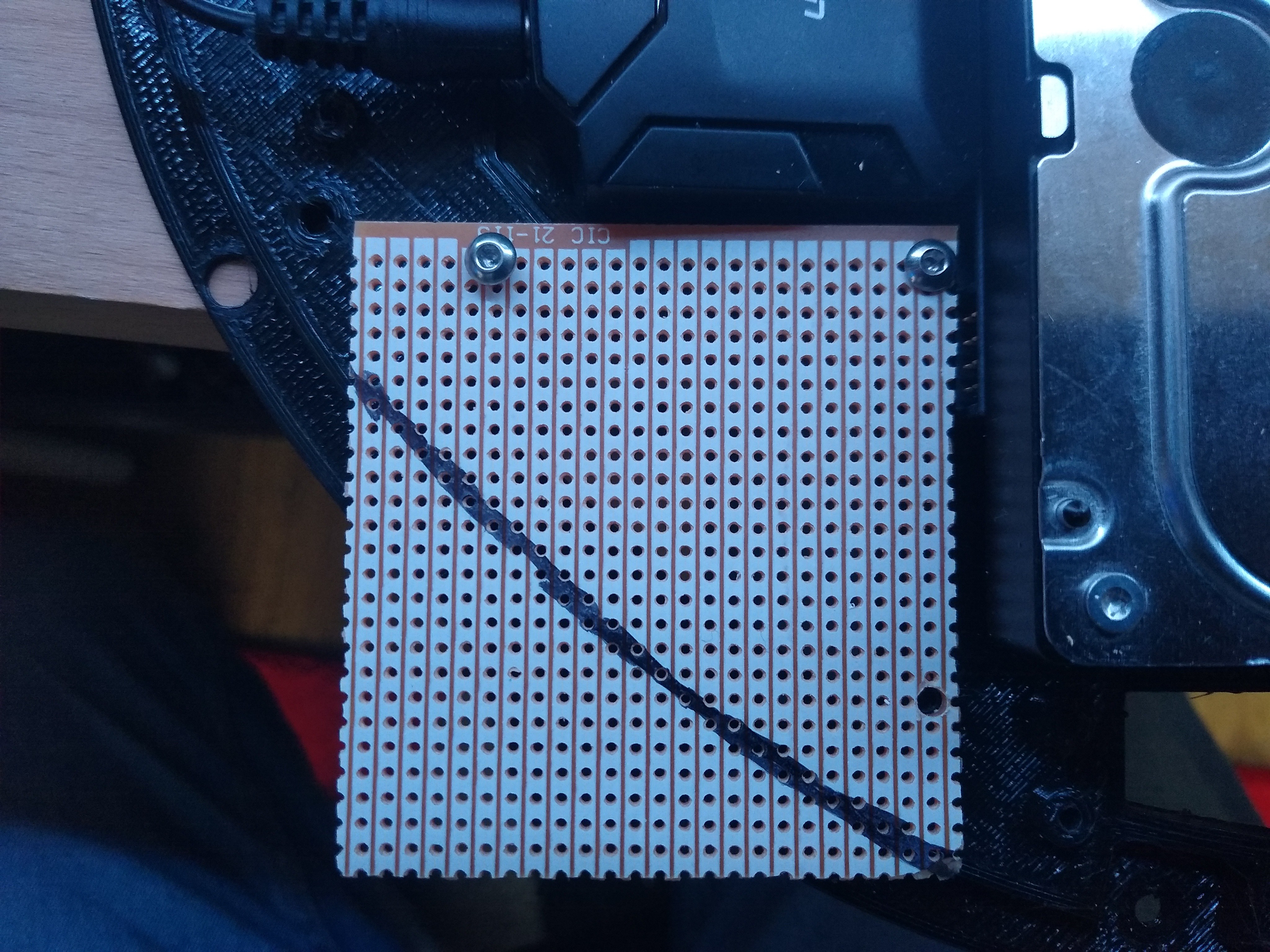
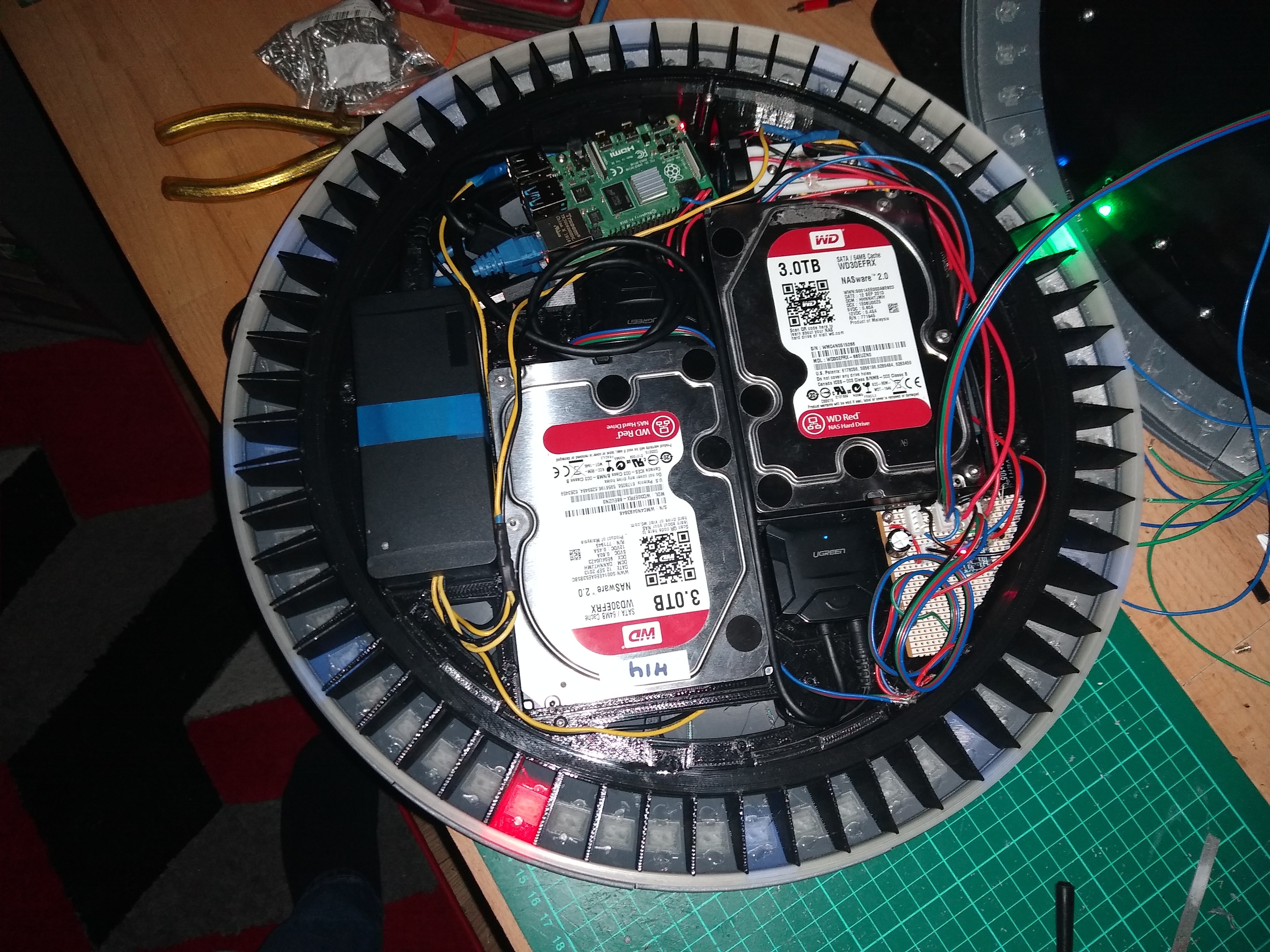
The NAS UFO has a space for a bit of stripboard which I snapped down to size in a vice after marking up:
![]()
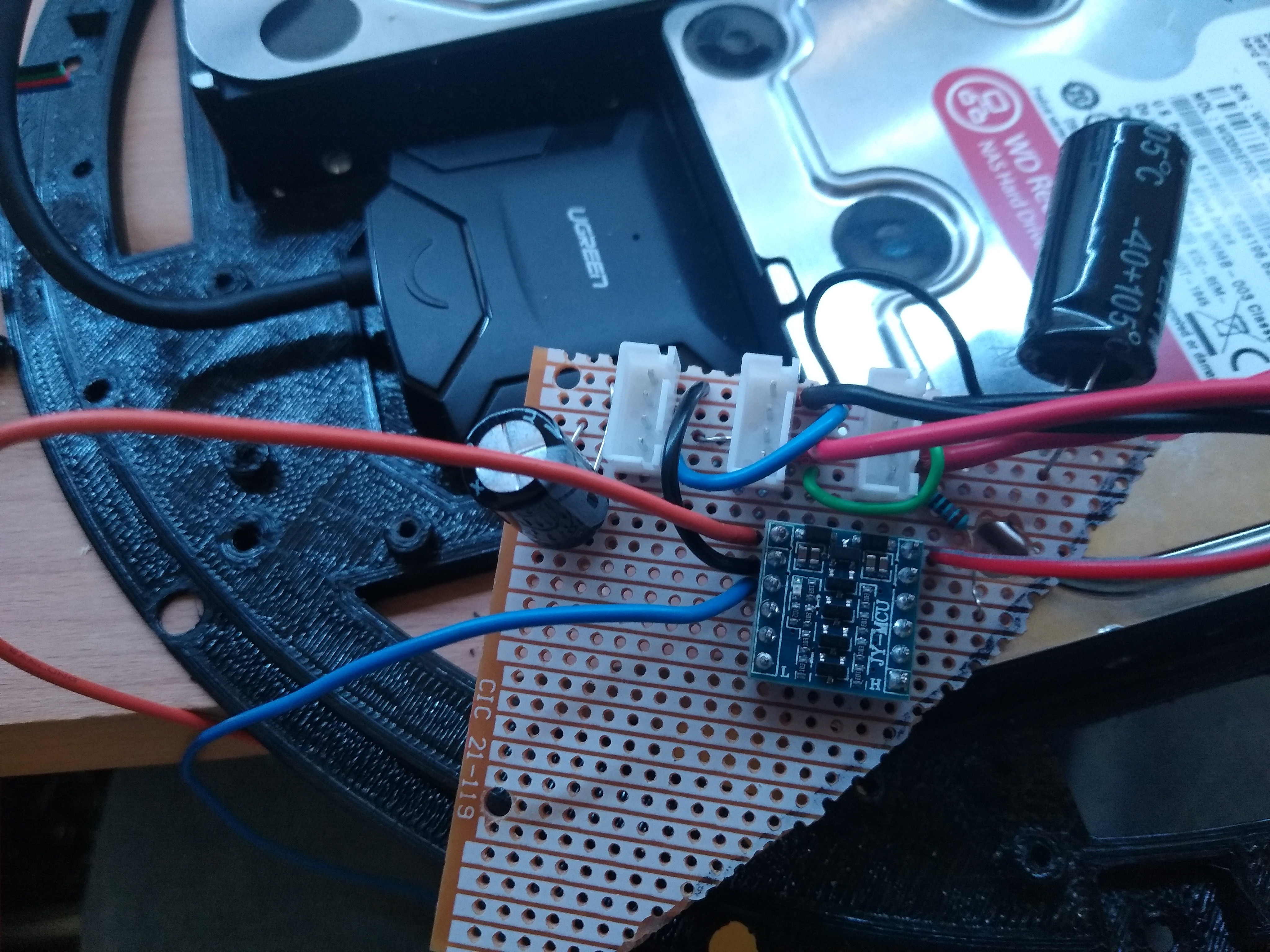
After populating and soldering it looked like this:
![]()
I used 3 JST-XH 4-pin connectors for the LED strips, with the outputs from daisy chained to the next LED strand's input. A big 1000uF cap was used for the big strip and a smaller 330uF for the smaller two. A 470ohm resistor fed into the first LED strand input, driven from the 5V output of the 3.3/5V signal converter board seen above. I later removed the 3.3V input from the signal converter as it wasn't needed (it floats to that voltage anyway in testing) and also because having it attached to the Pi's 3.3V GPIO header prevents a Pi 4 from booting up (no such problem with earlier models, and despite seemingly fixed with EPROM updates, I couldn't get it to work). Later on I added an 'out' connection from the final LED's JST connector so I could daisy-chain to the 'slave' UFO.
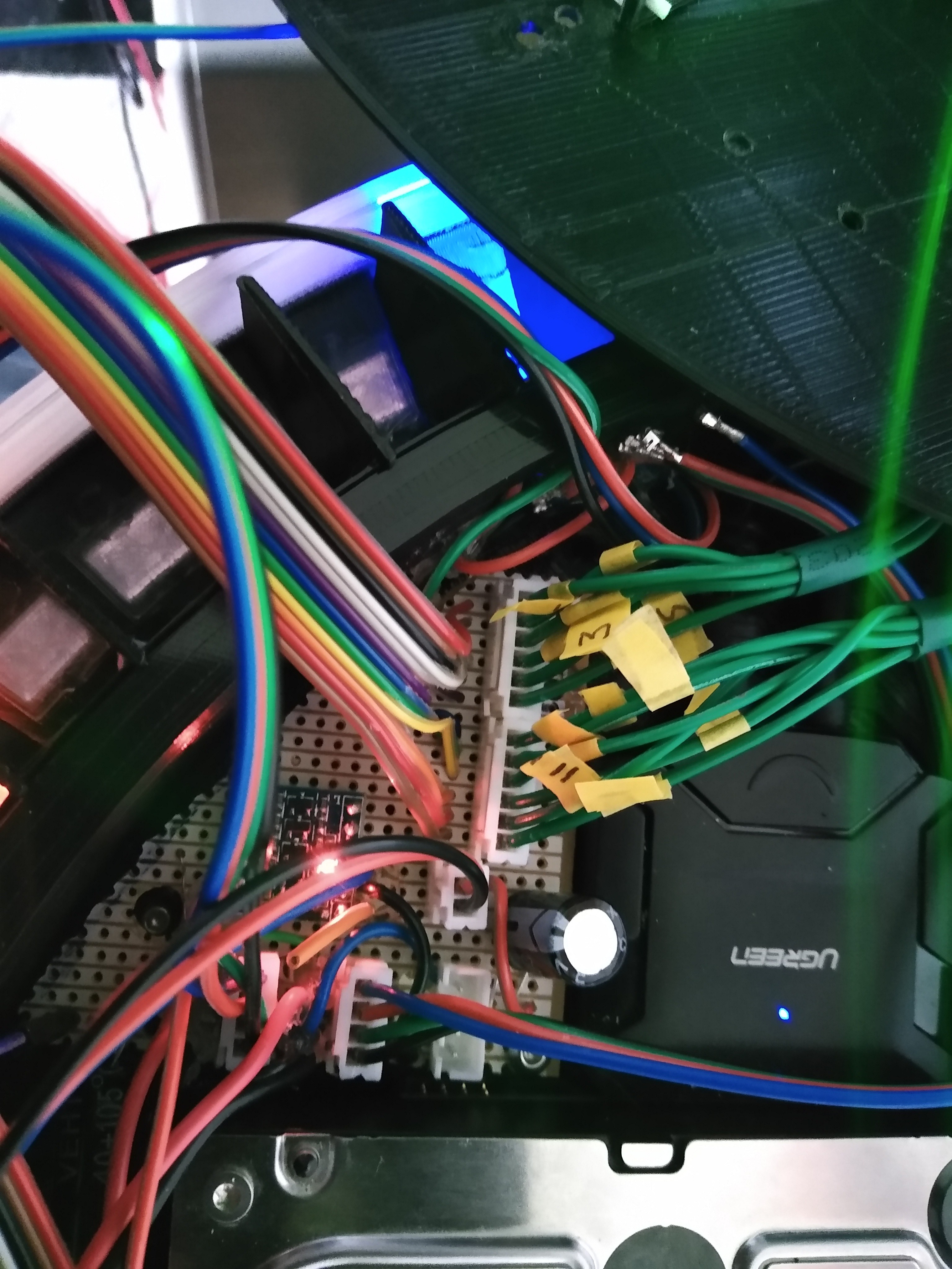
The remainder of the stripboard was later populated with 2 x 6-pin JST-XH connectors for the 12 input buttons. I soldered twelve jump wires from there to the Pi's GPIO pins and also added a single ground connection as a common to each of the 12 input buttons. The GPIOs are pulled high in code, so each button press takes the input to ground and this has proved perfectly reliable in use.
![]()
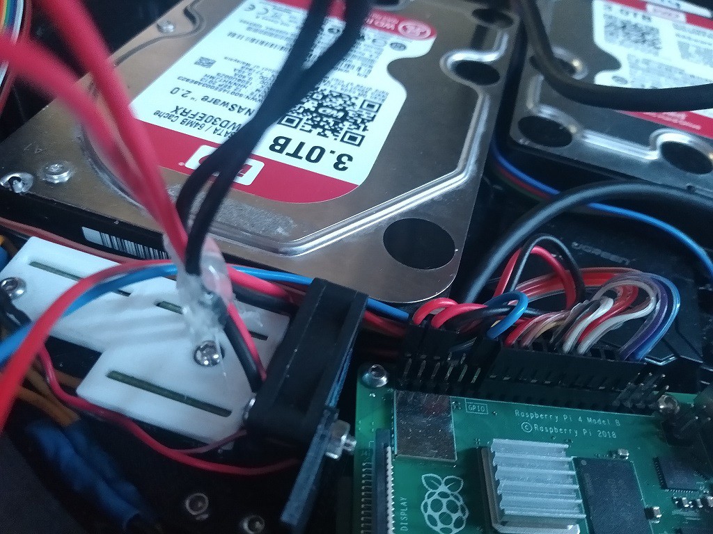
And to the GPIOs like this:
![]()
The Pi is powered by the buck converter directly onto the GPIOs.
-
5Putting it all together
The same technique as for constructing the top, minus the buttons and levers, is used to construct the bottom of the saucer. The light blockers are used between the outer LED ring and the outer diffuser to give crisp separation of the LEDs. In the future I might paint some of the parts white to increase reflectivity and light output.
![]()
The wiring for the top is completed with JST-XH connectors.![]()
Construction of the UFO top is completed by a set of 3 pieces: a diffuser and two top parts:![]()
The final part is connected with an M4 screw, as opposed to the M3 screws used elsewhere. -
6Step 6
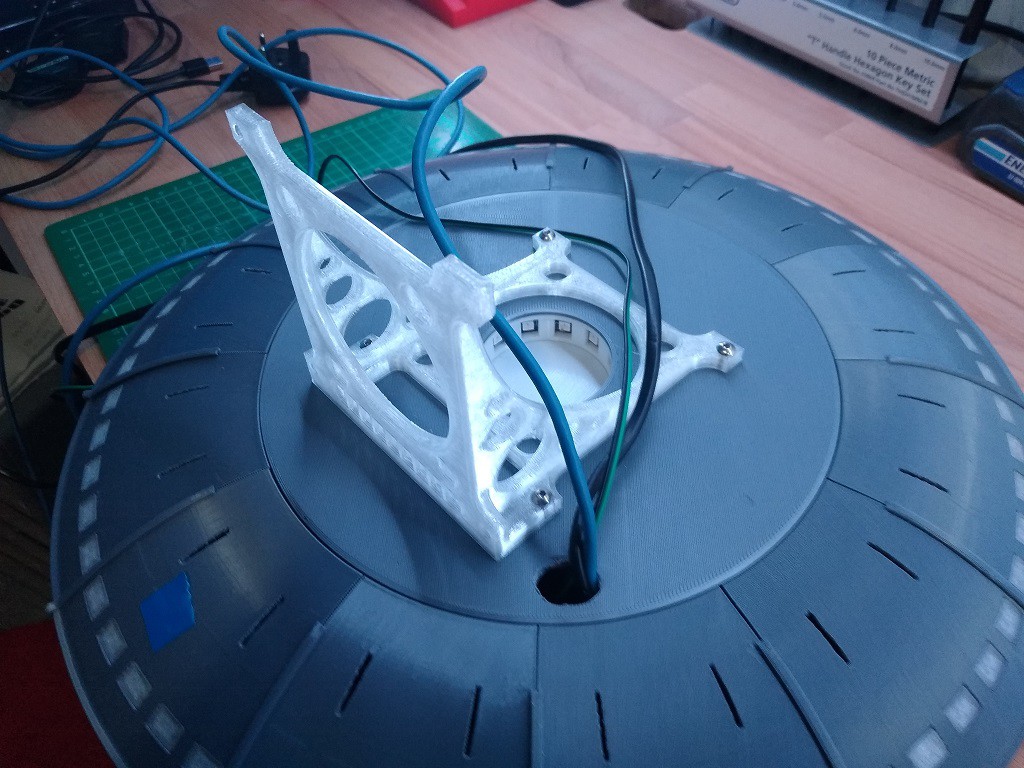
The bottom of the saucer can be attached to a 100mm VESA mount with M4 screws, used here for strength. The image below shows the mount together with the power lead, network cable (I don't like WiFi for a NAS, but you can use that if you like) and the daisy chain output for the slave saucer.
![]()
I made a quick right angled VESA mount (light but strong) so I could attach the UFO to a monitor mount and still see the light from the bottom LEDs. I will rework this in the future to make a translucent cone containing a cow abductee!
Flying saucer clock (and NAS!)
This digital clock uses a ring of 60 neopixels of a flying saucer design and 12 on the inner ring for hours. It also does backups.
 HarryTheB


Discussions
Become a Hackaday.io Member
Create an account to leave a comment. Already have an account? Log In.