 Josh Kittle
I learned a ton of lessons in the first 2 runs of the PCBs, and the Rev 3 PCB was really a turning point. I made this board revision a 4 layer PCB (my first 4-layer PCB for that matter) and it turned out great. In the end, I decided that I wasn't a fan of the way the flux residue stood out on the stark white PCBs, so there's that..... Here's a mock up of the Rev 3 PCB.
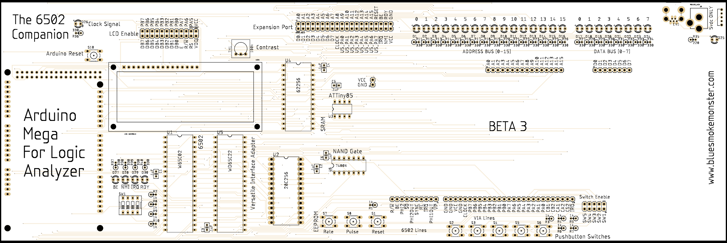
Loads of changes in this revision. I decided to stand the resistors up on end to make assembly a little bit easier, and be a little more efficient use of space. I also enlarged the board and added a footprint for an Arduino Mega to be used as a Logic Analyzer, a decision I'll later back off from, in favor of an expansion-module approach. Again, some layout changes as I played with what my eyes liked. One particular change of note is that I enlarged the socket holes on the EEPROM socket, and opened the spacing up a bit. This was in order to allow the installation of a ZIF socket, since the EEPROM, being what it is, will tend to be inserted and removed very frequently. This is also the first time that I soldered a USB connector on the board as a power option - something I later decide to lose. A few more bodges, and we were ready for Rev 4.
Here's a photo of one of my Rev 3 boards being tested. Again, only 5 of these boards were made.

Discussions
Become a Hackaday.io Member
Create an account to leave a comment. Already have an account? Log In.