I've been working on NEC decoding for a few weekends now, and I'm starting to understand it, although coding in C is tricky for me.
The basic premise is that an interrupt on rising/ falling edge change starts a timer and this is checked against the NEC condition.
I'm using this page by Simple Projects as a guide.
The message of the NEC protocol is 32-bit long, address (16 bits), command (8 bits), and inverted command (8 bits). Before the 32 bits there is 9ms burst and 4.5ms space.
A logic 1 is represented by 562.5µs burst and 562.5µs space (total of 1125µs) and a logic 0 is represented by 562.5µs burst and 1687.5µs space (total of 2250µs).
In my PIC16LF1708, I've got the external interrupt connected to pin A2 (input from IR receiver) on falling edge working with Timer0.
Todo:
- Make the external interrupt on A2 interrupt on change.
- Figure out what the numbers in the TMR0 register equate to, and if a different timer is needed.
TMR0 is 8 bits, so counts to 256 in 65ms (using INTOSC, 4MHz). Since the total length of a 1,2,3,4,5, or 6 on the NEC remote I have is about 56ms, it's fine for the moment. Might move to Timer1 later.
I'm having a lot of trouble getting the IOC (interrupt on change) to work. I've tried a few examples and they're simple enough, but the IOC happens intermittently. I'm thinking about soldering a debounce circuit onto my Curiosity board to filter out garbage signals.
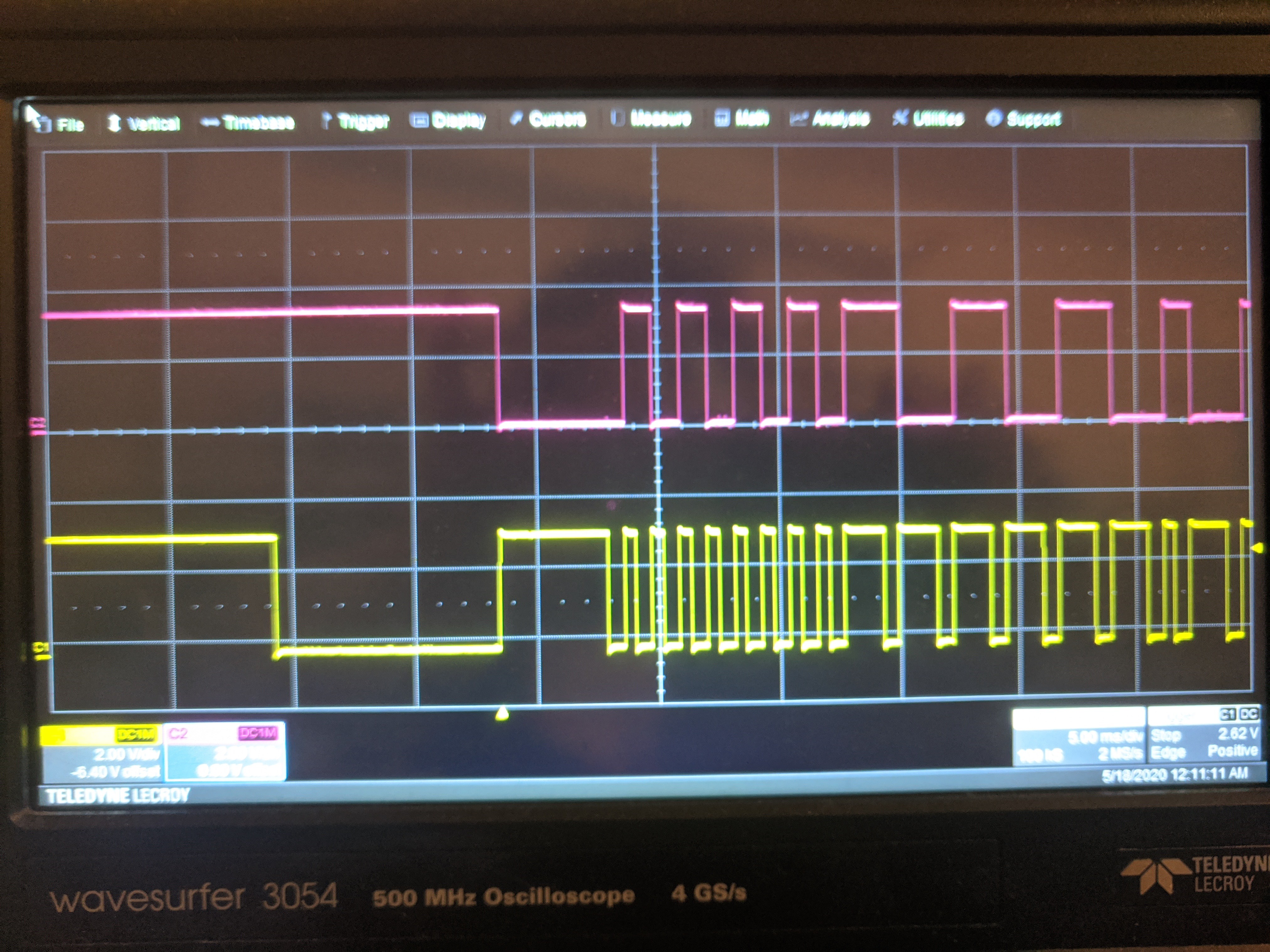
In the image below, the top signal is the interrupt, the bottom signal is pressing the "2" key on the remote control. I don't think it's a good enough match to decode.

 Sophi Kravitz
Discussions
Become a Hackaday.io Member
Create an account to leave a comment. Already have an account? Log In.
I had done NEC some years ago (with a PIC18F2550 to wit) and one of those fabulous Vishay receivers. I don't think you need any 'debounce' -- the Vishay's have pretty good circuity inside.
I will have to dig to find my original code, but I suspect you might also be wanting to go through the process yourself, so I won't foist it on you; lol.
One thing I find handy to do as a first step and sanity check in an ISR like this is simply twiggle a GPIO to repeat back the signal that's being received. So your two traces should look identical. If they are /not/ identical, then probably some configuration of the interrupt is faulty (since you are wanting to trigger on both edges), and also you can inspect what is your latency in servicing. (I'm pretty sure you are good on latency with that device, though.) After I validate the hardware assumption, then I make the state machine that decodes.
Lastly, as for measuring event durations, you don't strictly need to reset the counter to zero. If the counter has a sane number of bits (e.g. 8 or 16 or 32), then two-complement arithmetic will always work even if you roll over (but only once) as 'duration = timeNow - timeThen'. As to whether this actually makes sense in your project I can't know; you might actually want to reset for other reasons (e.g. a timeout interrupt).
Are you sure? yes | no
I fixed it by toggling the edge bit. Timer0 has 8 bits, and I'm using that right now. I might move to Timer1 (16 bits) but not sure.
Are you sure? yes | no
I did find my code (10 years old, lol!) It's been a long time since I did the 8-bit PICs, but I noticed that I also manually toggled the edge trigger. Maybe that is required; would have to check the data sheet.
I did notice your new post -- signal looks great! You're well on your way to fame and fortune!
Are you sure? yes | no
There is no other code in the ISR, but I am (unfortunately) not triggering on both edges as I thought. Seems that I am only interrupting on the rising edge.
Are you sure? yes | no
That makes more sense.
Thanks for sharing.
Are you sure? yes | no
That scope plot looks weird. The interrupt matches with the rising edge of the signal, but there is a delay on the falling edge. Is there a lot of code in the ISR that slows down the interrupt too much?
Are you sure? yes | no