 John Anderson
The next step was to build the controller board and interface it with the original PCB with power supply, 7441 decoders/drivers, nixie tubes.
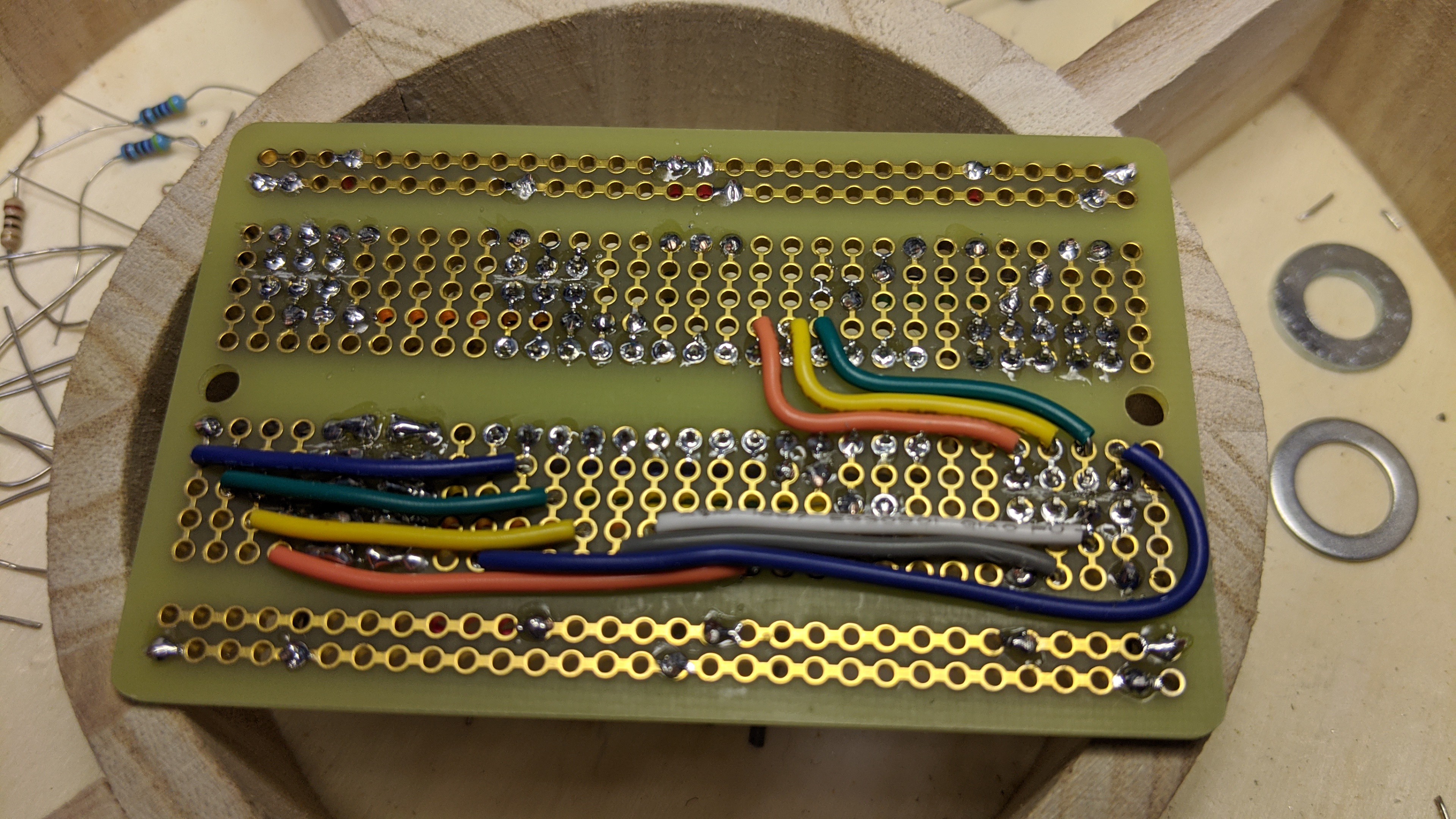
I started with the interface to the PCB. I wired up the a small piece of protoboard with four 7 pin single row headers and a 10 pin dual row header. The single row headers line up with the 7490 decode counter sockets in the original PCB. To make that work, I pressed the single row headers into the sockets and then put the protoboard onto the headers. I soldered the headers to the protoboard there in place. This ensured they line up perfectly. Then I wired up the Vcc, Gnd, Output A, Output B, Output C, and Output D to the 10 pin connector.
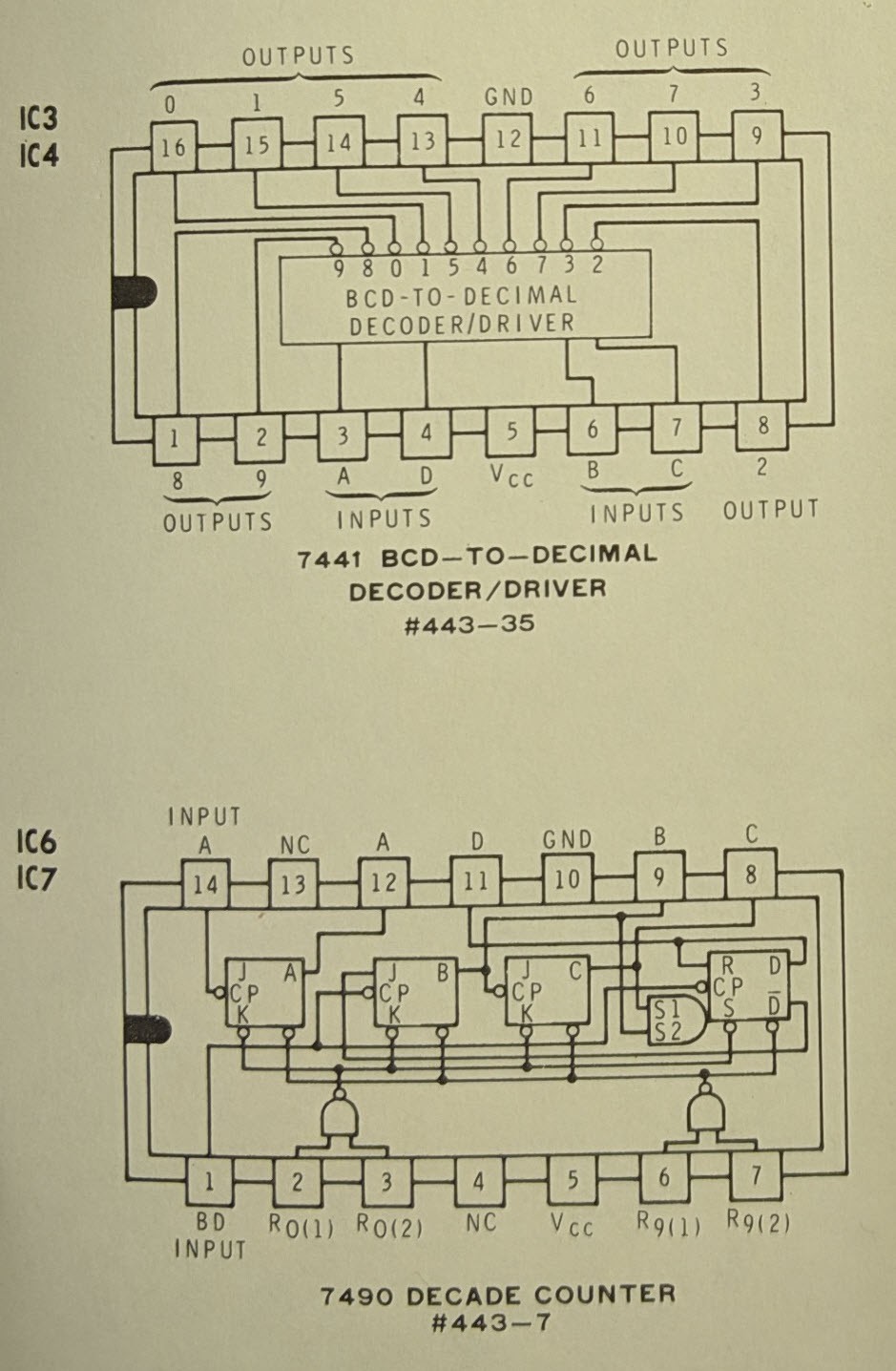
For more details and schematics regarding the original PCB, checkout these logs from the original project: Let there be light... and Getting Started...
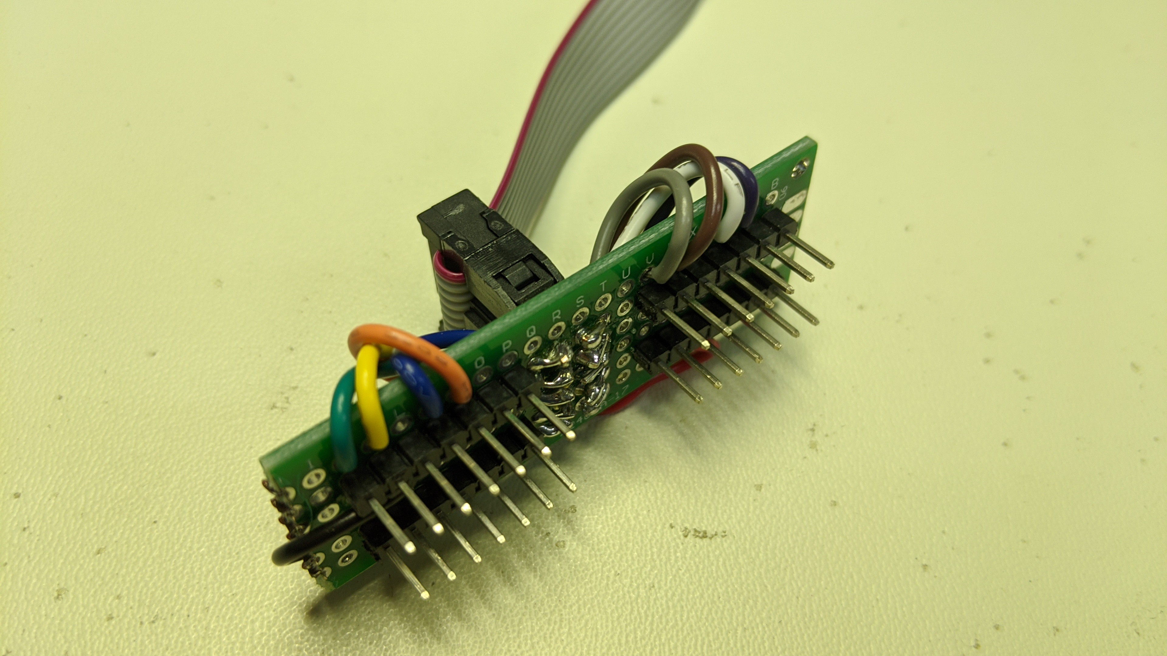
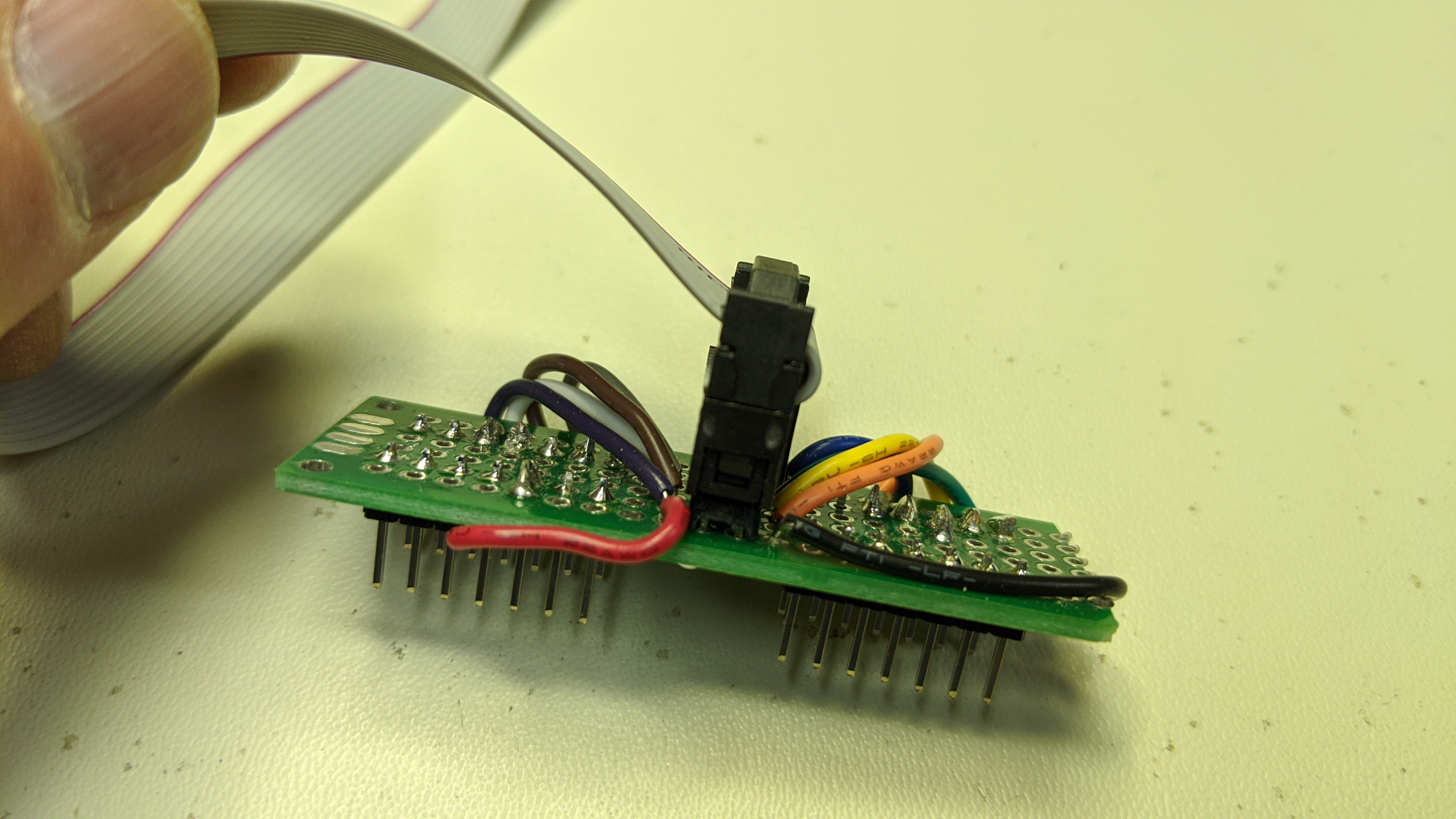
The protoboard that interfaces to the original PCB looked like this when I was done.
Next, I wired up the controller board. It contains the ATmeg328 microcontroller and connectors to the original PCB, thumbwheel switch, rotary switch, LED/push button/speaker daughter board, and ISP programming/debug port. I am using the integrated oscillator so once again the controller board is just the controller, wires, and connectors.
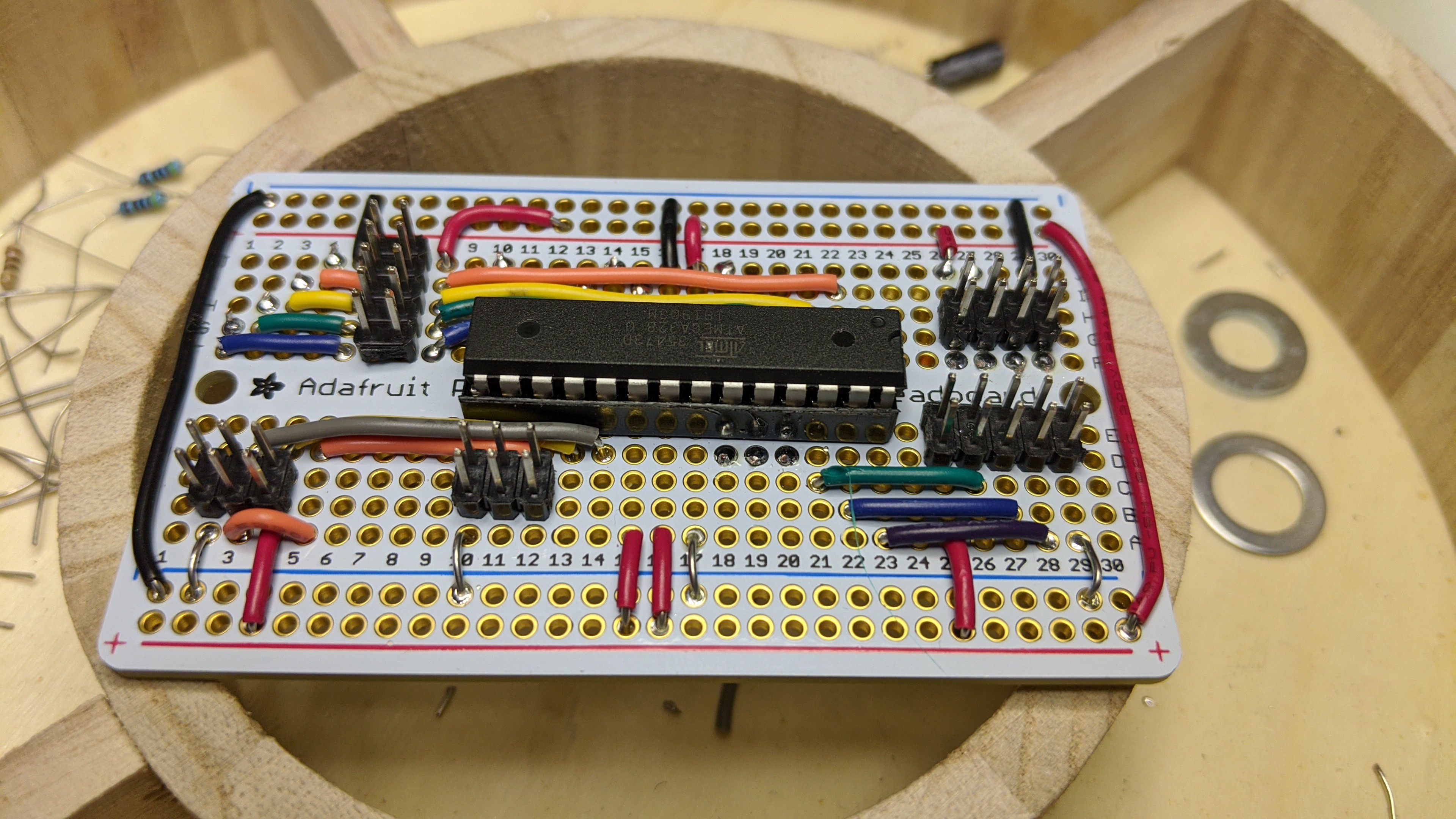
Note: If you look closely, you can see where I cut traces on the protoboard so I could used the dual row connectors. I've seen some breadboard style protoboards lately that have the traces on both sides under a solder mask. Don't buy those. I really like these Adafruit protoboards because they use thin traces that are easy to cut and the holes are plated through.
Lastly, I selected a location on the original PCB to mount the controller board. I picked a spot on the right side of the board behind the switched where I could drill without cutting existing traces.
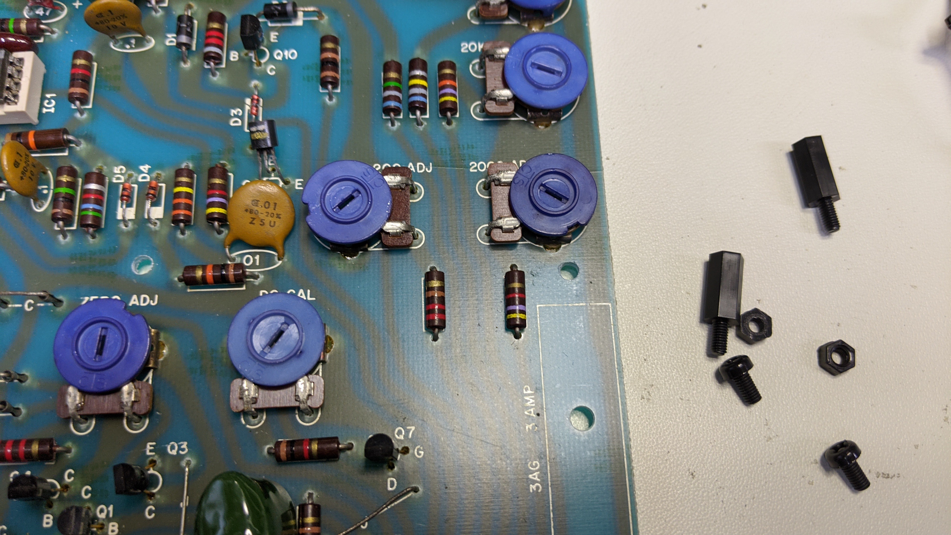
I installed the standoffs.
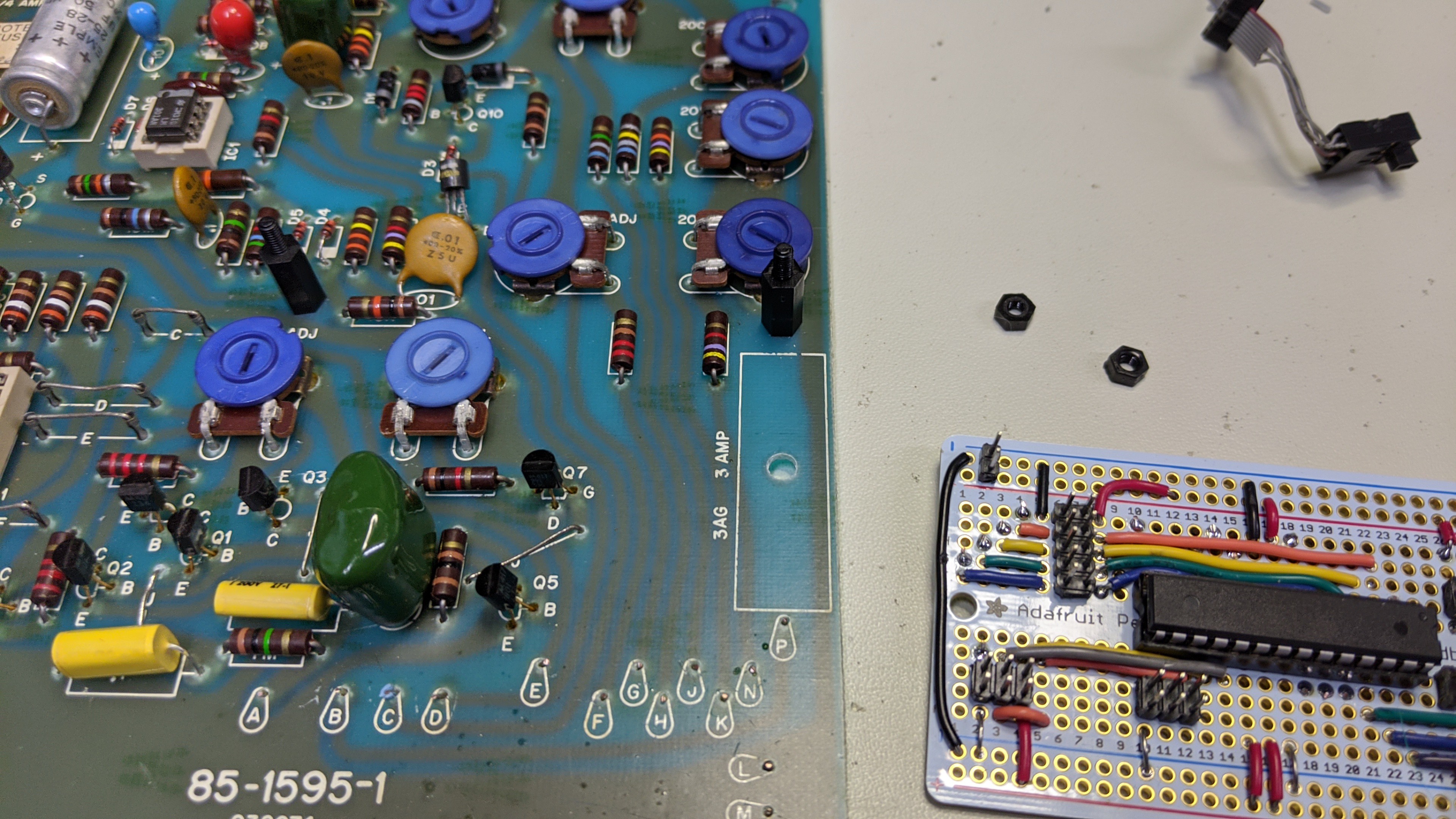
And, I installed the controller board.
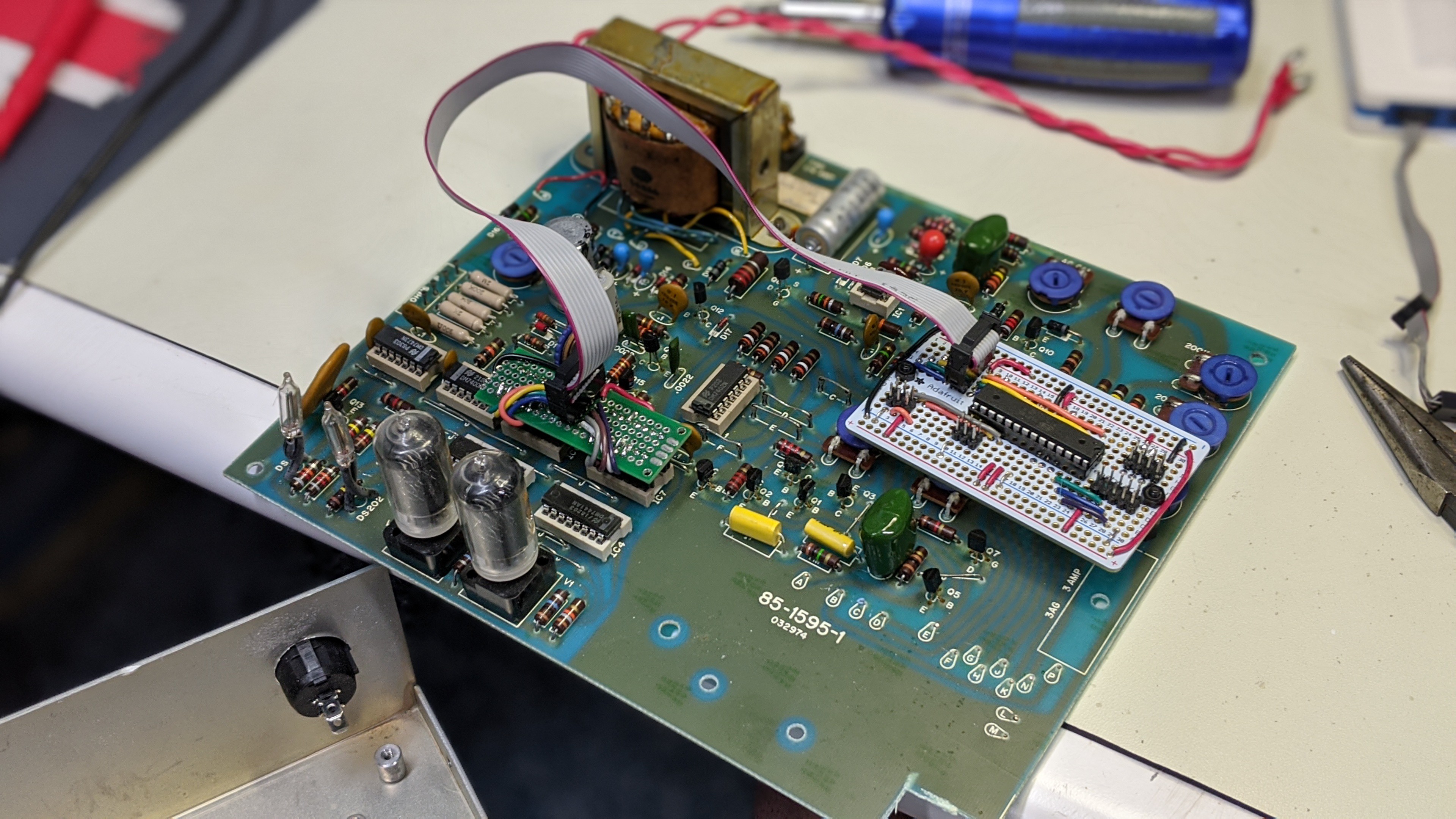
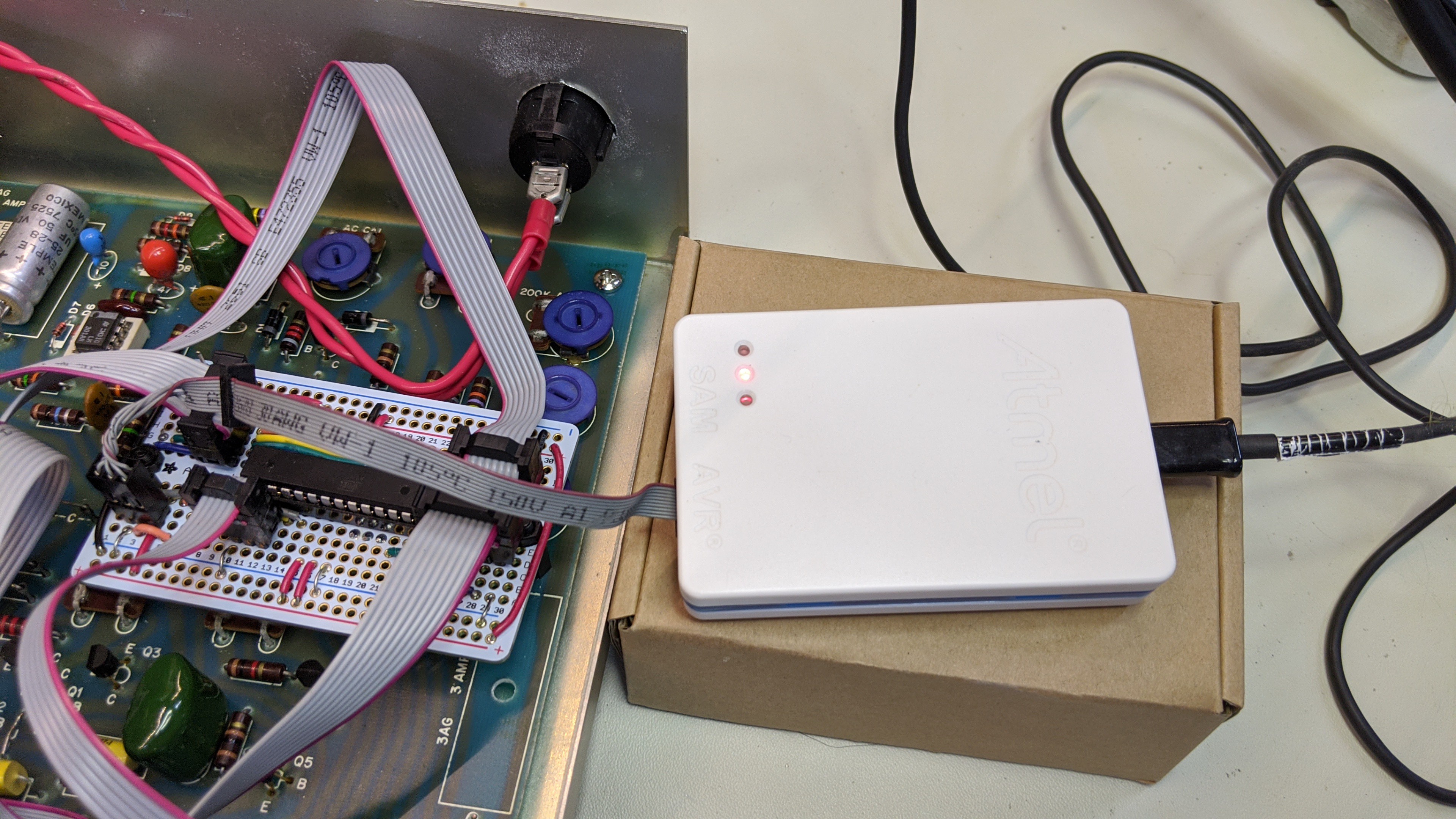
It looks like this in the case with the programmer/debugger connected.
Discussions
Become a Hackaday.io Member
Create an account to leave a comment. Already have an account? Log In.