land-boards.com
-
ANSI Terminal with Z80 CPU Card
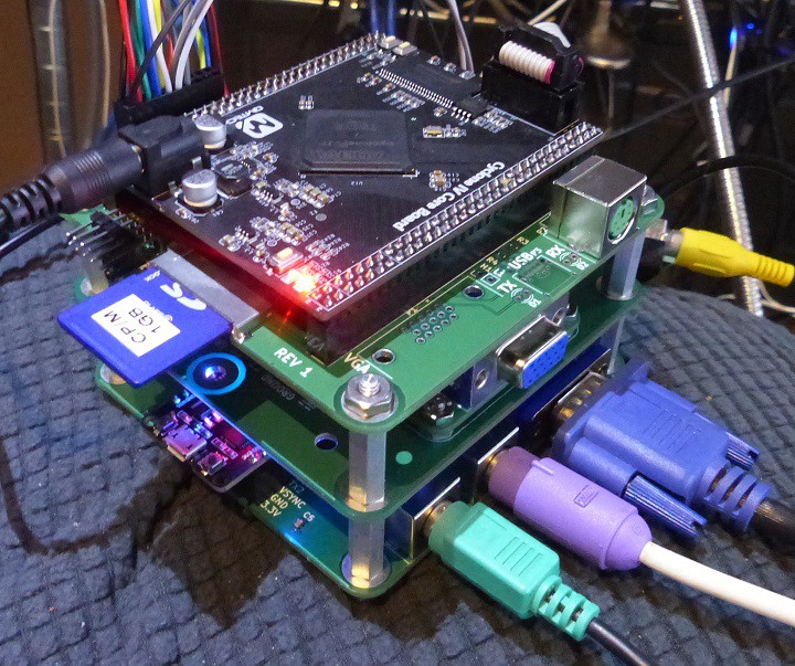
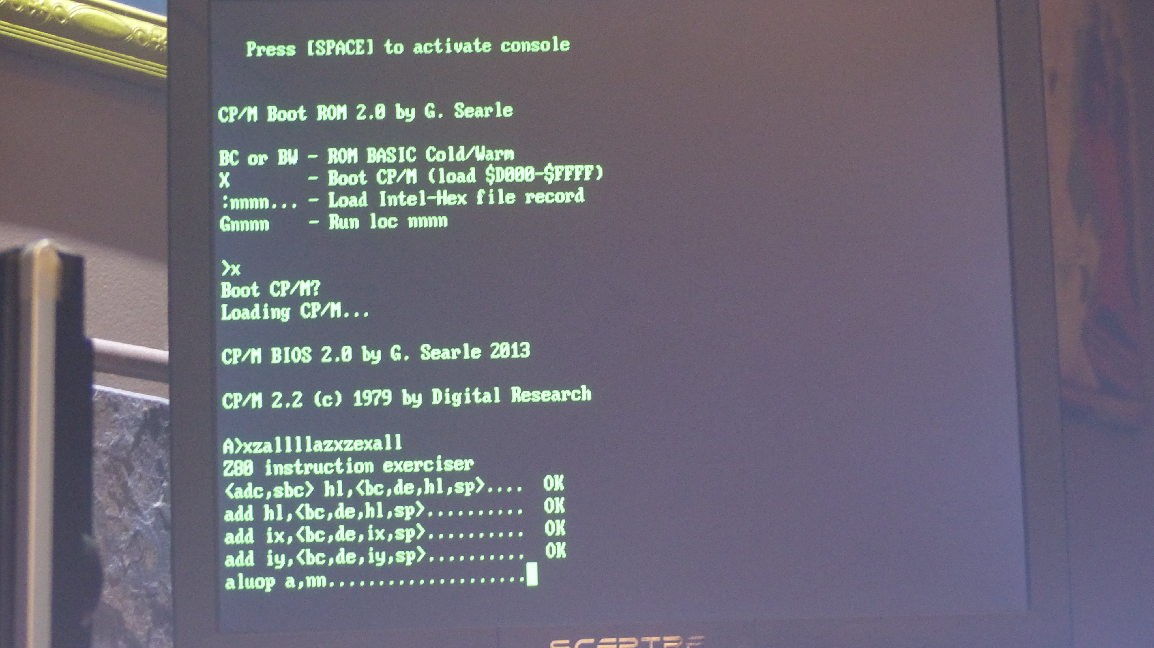
02/22/2020 at 21:53 • 0 commentsStacked the ESP32-VGA with the RETRO-EP4CE15 card. The ESP32-VGA card is running the ANSI terminal sketch by FabGL. Makes a great retro computer setup.

The RETRO-EP4CE15 card has an Altera/Intel EP4CE15 FPGA and 1MB of SRAM. The card runs CP/M. VHDL code is Grant Searle's Multicomp.
-
Rev 1 VGA Resistors
02/17/2020 at 15:44 • 0 commentsI have the Hi/Low resistors swapped on the Rev 1 card. Easily reworked.
Consequence is the dimmed video is not as dim as it should be on the ANSI terminal header.
[Update] I dug a little deeper. Looks like the FabGL has contradictions in their web pages. One page seems to have the order different from the other. I was using the one page to define the pins when I did the above update. I think the original schematic was actually correct. Switching back.
The TerminalCharSet sketch shows this behavior well. When I swapped the resistors the screen got really dim. Switching the r0/r1, etc in the sketch initializer fixed the problem. I am going to switch back the parts on the card to the original order.
VGA Output Levels
Some pages say VGA output is 0.7V pp. This seems to be based on the composite video spec. Assuming that VGA inputs are AC coupled that could make sense. Composite video (IIRC) has a swing down to -0.3V for the sync. Black is 0V. The white level is 0.7V.
This makes me conclude that the original 400/800 ohm values are correct. Standard (5%) values are 390 and 810 ohms.
-
Space Invaders
02/09/2020 at 21:14 • 0 comments -
VGA Drive Simulation in LTSpice
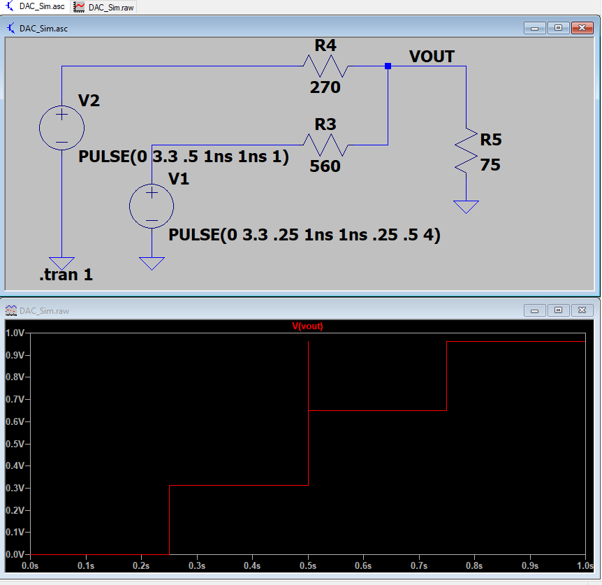
02/09/2020 at 21:10 • 0 commentsThe FabGL design has 400 and 800 ohm summing resistors. These are not standard values and don't achieve the possible drive for a VGA monitor.
The VGA monitor has 75 ohm termination. The full intensity voltage is 1V.
The ESP32 has a lot of drive current. Enough to drive a 75 Ohm resistor easily.
I ran a simulation and picked the best common resistor values. The best values are 270 and 560 ohms.
-
Card Tests
02/09/2020 at 21:01 • 0 commentsGenerally, the card runs pretty well. All of the FabGL sketches run.
Serial Port Connection
The early FabGL schematic had a wrong pin for the serial port. The pin, GPIO12 was corrected (changed) to be GPIO34. Rev 2 of this PCB will use the pin. The downside of this is that the Rev 1 card can't download sketches from the Arduino when there is a powered FTDI connection on the port. The FTDI cable can be disconnected, or the FTDI cable can be left connected and the USB cable can be removed from the FTDI connector.
The reason for this seems to be that GPIO12 can't be driven when the card is being programmed due to sharing the line with the internal SPI Flash Memory. The card can be removed from the board and programmed just fine.
This also means that the FabGL sketch for the ANSI terminal needs a small change to use GPIO12 instead of GPIO34 for serial connections.
Hi/Lo VGA lines
Lines were swapped on the Rev 1 board. This was easy enough to correct on the schematic but could also be fixed by changing the pins used in the Arduino sketch. Will fix the silkscreen on the Rev 2 board.
SD Card Connections
Adding an SD Card connector on the Rev 2 version of the board. Some of the sketches use it as storage. The pins are on the GVS connector. This will reduce the number of GPIO lines left over.
DC Power
The card can be powered from an external 5V DC power adapter. The rev 1 board has some options which really don't work. All that is really needed is a jumper to remove the DC jack power if the ESP32 module has the USB cable attached. The Rev 2 version of the board will reduce this to a single 1x2 header.
There's even less need for a 3.3V regulator on the card since the GPIO lines are reduced due to the SD Card connections. Rev 2 of the board eliminates the regulator.
FTDI #1
FTDI #1 is connected to the same UART connections as the USB to Serial converter. Not sure if it would work or not but leaving it on Rev 2 of the card.
Audio
Audio works just fine but it's a bit noisy.
Keyboard/Mouse
The PS/2 keyboard/mouse also work great. This card has a level translator for converting the 5V of the keyboard into 3.3V for the ESP32. This is a better design than using current limit resistors.
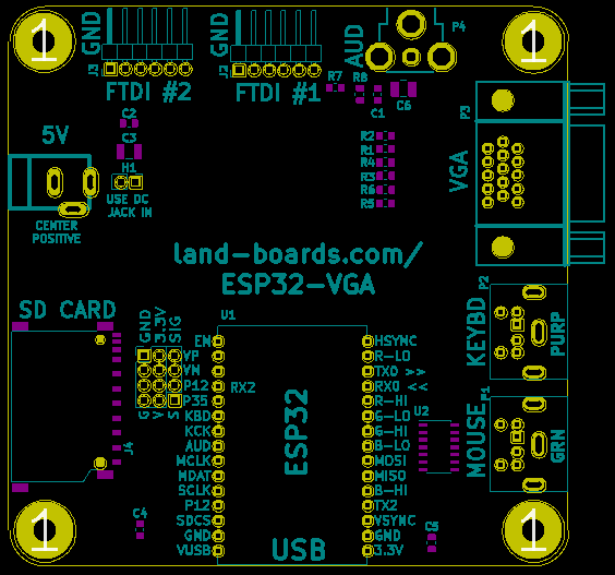
Reference Designator Updates
I re-sequenced the board reference designators for the Revision 2 board. The Rev 2 layout is: