Christoph Tack
-
LED driver
03/13/2020 at 21:05 • 0 commentsLessons learned from #TritiLED
- 530nm peak falls in between the scotopic (507nm) and photopic (555nm) human eye sensitivity peaks.
- Efficient way of driving the LED by connecting it as protection diode in a relay. It's better than connecting it as in a boost LED driver because that leaves a current path to ground at all times.
Series resistor
The simplest, but certainly not the most efficient way to drive an LED. To limit power consumption, the resistor should be chosen as large as possible. Unluckily LEDs are not very efficient at these low currents.
Fly back diode on inductor
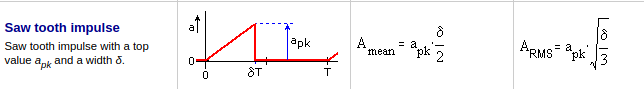
The current through the LED will be a sawtooth with a falling slope (unlike a rising slope in the image below). That doesn't impact the RMS-value.
![]()
RMS value of a sawtooth impulse In our case, delta will be 100%, or 1. So the peak current in the saw tooth is 1.73 times the RMS-current in the sawtooth pulse. For an RMS-current of 5mA, we must generate a sawtooth with a peak current close to 9mA.
As our supply voltage will be fixed, the only parameters left to play with, are the inductance value and the pulse width.
Parameters
- Pulse frequency : greater than or equal to 50Hz to avoid flickering
Simplified calculations
Simplified in a way that no losses are taken into account.
Needed pulse width
Calculation of the pulse width at the gate of the MOSFET. Example for an inductor of 1mH, 3V supply voltage and a peak inductor current (top of the sawtooth) of 9mA You could choose a smaller inductor value, but this also decreases the pulse width. Smaller pulse widths require smaller RC-combinations for the one-shot timer. This will lead to increased loss (smaller R) or less precision (C is only a few picofarads).
Either one or two LEDs will be used as a load. When two LEDs are connected in series, the inductor current drops to zero in about half the time as when only one LED would be connected. Either the LEDs are still bright enough, then the 1mH inductor can remain. If not, then the inductor value and pulse width can be doubled.
Current consumption
Here we calculate the DC-current consumption, as would be shown on a multimeter feeding this circuit.
Example calculation with inductor = 1mH, peak inductor current is 9mA, pulse repetition frequency is 64Hz and a LED voltage of 2.6V (when the current through the LED is 9mA).
Schematic

LED driver for one or two LEDs The LED driver itself is quite simple. If Q2 conducts, current starts rising in the inductors. Once Q2 stops conducting, the inductor will create a negative voltage on the cathode of D2, and the current will flow through the LEDs.
The extra inverter consisting of Q6 and R14 has been added because I didn't want to add an extra transistor to the BoM, instead I reused the FDV301 and the SI3401A.
This circuit doesn't work as intended, i.e. creating 3µs ON-times for Q2. Can you spot the error?
I overlooked the discharging of the Q2 gate capacitance. To pull Q2 into conduction, Q6 conducts and charges Q2 fast. When Q6 stops conducting however, the Q2's gate has to discharge through R14, which is 100K. This takes about 180µs!
The dirty remedy would be to drastically lower R14, but that will also lead to a waste in current. The nice solution is to replace Q6 by a low Rdson NMOS and connect the LEDs and the inductors between the VCC and the drain of Q6.
For Q6, #TritiLED uses the IRLML6244TRPBF, but that MOSFET has a total gate charge of 8.9nC.
I think there's no point in selecting the NFET with the lowest possible Rdson, because the bulk of the resistive loss occurs in the inductors, which have 1.85ohm series resistance each.

Replacing Q6 by a ZXMN2F30FHTA and correcting the other components. The current consumption of this setup is about 1.45µA, which is much higher than what was expected. What is going on?
- When replacing the inductor || LED with a 1Mohm resistor, the current consumption is still 280nA.
- Replacing Q6 with a 1Mohm resistor to GND : 77nA.
- When disconnecting the Q output of the monostable, current consumption drops to 66nA.
It's clear that the (gate) losses of the MOSFET have to be taken into account, as pointed out on MOSFET power losses and how they affect power-supply efficiency. The BSS806NH6327XTSA1 might be a better choice as switching element because of its much lower gate charge. When the monostable drives the BSS806 with a 1Mohm resistor, the current consumption is 220nA. So we win 60nA in comparison to the ZXMN2F30FHTA.
-
low power timer
03/13/2020 at 19:21 • 0 commentsDuty cycle
- 10ms ON = minimum needed for people to perceive full LED brightness
- 2s period = human beings are attracted by flashing periods from 0.5 to 5s. 2s is about in the middle of that range.
TPL5110 Low power timer
The TPL5110 is a very low power timer chip. Unfortunately, the minimum period is 100ms. This rules it out as an oscillator to generate LED pulses. To have a flicker free LED, the period should be equal to or lower than 20ms.
The TPL5110 could be used however to control the flashing period, in case flashing is desired.
14-03-2020
Circuitry
Yesterday's circuit worked fine, but it was overly complicated. This one does better. The BSS169 is a depletion NMOS. It's used here as a low power series regulator so that the 15nF is always charged at the same rate, no matter what input voltage is applied to the TPL5110. The source voltage of the BSS169 is about 2.2V for the charge current used in this application.
When powering at 3V3, the FDV301 triggers after 25ms, at 5V it triggers after 24.2ms.To evaluate the TPL5110, the PRT-15353 from Sparkfun has been used. When the output of the TPL5110 is off, the current consumption is less than 100nA. It should be 35nA according to the datasheet.
![]()
Simple delayed output After 25ms, the FDV301 releases the DONE-pin. Once DONE is high, the OUT will be powered down.
![]()
Green = TPL5110 OUT, Blue = TPL5110 DONE
13-03-2020
Circuitry
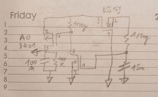
To flash the LED, a TPL5110 is used. It will power up the LED every 2s. The circuit below turns the TPL5110 off again after 5ms. It should be >10ms. The 15nF capacitor needs to be increased. The drain of the AO3401 is connected to the DONE-pin of the AO3401.
![]()
TPL5110 Turn off circuit Once the output turns on, the 15nF starts charging. After about 5ms the done-pin goes high. The output of the TPL5110 quickly goes down again. After that, the voltage slowly decays.
![]()
Green = TPL5110-OUT, blue = TPL5110-DONE
Ultra low power LED
<1.5µA current consumption when continuously on, optional flashing mode